1
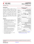
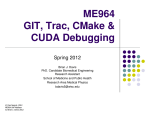
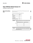
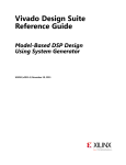
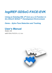
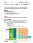
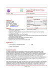
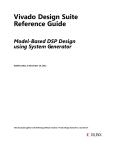
LogiCORE IP
Reed-Solomon
Encoder v8.0
Product Guide
PG025 January 18, 2012
Table of Contents
Chapter 1: Overview
Standards Compliance . . . . . . . . . . . . . . . . . . . . . . . . . . . . . . . . . . . . . . . . . . . . . . . . . . . . . . .
Licensing . . . . . . . . . . . . . . . . . . . . . . . . . . . . . . . . . . . . . . . . . . . . . . . . . . . . . . . . . . . . . . . . . . . .
Performance . . . . . . . . . . . . . . . . . . . . . . . . . . . . . . . . . . . . . . . . . . . . . . . . . . . . . . . . . . . . . . . . .
Resource Utilization. . . . . . . . . . . . . . . . . . . . . . . . . . . . . . . . . . . . . . . . . . . . . . . . . . . . . . . . . .
4
4
5
6
Chapter 2: Core Interfaces
Port Descriptions . . . . . . . . . . . . . . . . . . . . . . . . . . . . . . . . . . . . . . . . . . . . . . . . . . . . . . . . . . . . . 8
Chapter 3: Customizing and Generating the Core
Parameter Values in the XCO File . . . . . . . . . . . . . . . . . . . . . . . . . . . . . . . . . . . . . . . . . . . 15
Output Generation . . . . . . . . . . . . . . . . . . . . . . . . . . . . . . . . . . . . . . . . . . . . . . . . . . . . . . . . . . 20
System Generator for DSP Graphical User Interface . . . . . . . . . . . . . . . . . . . . . . . . . 20
Chapter 4: Designing with the Core
Functional Description . . . . . . . . . . . . . . . . . . . . . . . . . . . . . . . . . . . . . . . . . . . . . . . . . . . . . . 21
Block Code Settings . . . . . . . . . . . . . . . . . . . . . . . . . . . . . . . . . . . . . . . . . . . . . . . . . . . . . . . . . 22
Chapter 5: Detailed Example Design
Demonstration Test Bench . . . . . . . . . . . . . . . . . . . . . . . . . . . . . . . . . . . . . . . . . . . . . . . . . . 25
Appendix 6: Migrating
Parameter Changes in the XCO File . . . . . . . . . . . . . . . . . . . . . . . . . . . . . . . . . . . . . . . . . . 27
Port Changes . . . . . . . . . . . . . . . . . . . . . . . . . . . . . . . . . . . . . . . . . . . . . . . . . . . . . . . . . . . . . . . . 28
Appendix 7: Additional Resources
Xilinx Resources . . . . . . . . . . . . . . . . . . . . . . . . . . . . . . . . . . . . . . . . . . . . . . . . . . . . . . . . . . . .
Solution Centers . . . . . . . . . . . . . . . . . . . . . . . . . . . . . . . . . . . . . . . . . . . . . . . . . . . . . . . . . . . .
References . . . . . . . . . . . . . . . . . . . . . . . . . . . . . . . . . . . . . . . . . . . . . . . . . . . . . . . . . . . . . . . . . .
Technical Support . . . . . . . . . . . . . . . . . . . . . . . . . . . . . . . . . . . . . . . . . . . . . . . . . . . . . . . . . . .
Ordering Information . . . . . . . . . . . . . . . . . . . . . . . . . . . . . . . . . . . . . . . . . . . . . . . . . . . . . . .
Revision History . . . . . . . . . . . . . . . . . . . . . . . . . . . . . . . . . . . . . . . . . . . . . . . . . . . . . . . . . . . .
Notice of Disclaimer . . . . . . . . . . . . . . . . . . . . . . . . . . . . . . . . . . . . . . . . . . . . . . . . . . . . . . . .
Reed-Solomon Encoder v8.0
PG025 January 18, 2012
www.xilinx.com
29
29
29
29
30
30
30
2
LogiCORE IP
Reed-Solomon Encoder v8.0
Introduction
LogiCORE™ IP Facts Table
The Reed-Solomon Encoder is used in many Forward
Error Correction (FEC) applications and in systems
such as communications systems and disk drives
where data is transmitted and subject to errors before
reception.
Features
•
Automatically configured by user-entered
parameters
•
Efficiently handles multiple channels
•
Supported
Device
Family(1)
Zynq™-7000, Artix™-7, Virtex®-7, Kintex™-7,
Virtex-6, Spartan®-6
Supported User
Interfaces
AXI4-Stream
Resources
See Table 1-1.
Provided with Core
Implements many different Reed-Solomon coding
standards, including all ITU-T J.83 and CCSDS
codes
•
Core Specifics
Design Files
Netlist
Example
Design
Not Provided
Test Bench
VHDL
Constraints File
Not Applicable
Fully synchronous design using a single clock
Simulation
Model
Verilog, VHDL
•
Supports continuous output data with no gap
between code blocks
Supported S/W
Driver(2)
•
Symbol width from 3 bits to 12 bits
•
Code block length variable up to 4095 symbols
with up to 256 check symbols
•
Block length can be changed in real time
•
The number of check symbols can be changed in
real time
•
Supports shortened codes
•
Supports any primitive field polynomial for a
given symbol width
•
User-configured generator polynomial
N/A
Tested Design Tools
CORE Generator tool 13.4
System Generator for DSP 13.4
Design Entry
Tools
Simulation ()
Mentor Graphics ModelSim
Cadence Incisive Enterprise Simulator (IES)
Synopsys VCS and VCS MX
ISim
Synthesis
Tools ()
XST 13.4
Support
Provided by Xilinx @ www.xilinx.com/support
1. For a complete listing of supported devices, see the release notes
for this core.
•
AXI4-Stream compliant interfaces
•
Use with Xilinx CORE Generator™ software and
Xilinx System Generator for DSP 13.4
2. Standalone driver details can be found in the EDK or SDK directory
(<install_directory>/doc/usenglish/xilinx_drivers.htm). Linux OS and driver
support information is available from http://wiki.xilinx.com.
3. For the supported versions of the tools, see the ISE Design Suite
13: Release Notes Guide.
Reed-Solomon Encoder v8.0
PG025 January 18, 2012
www.xilinx.com
3
Product Specification
Chapter 1
Overview
Reed-Solomon codes are usually referred to as (n,k) codes, where n is the total number of
symbols in a code block and k is the number of information or data symbols. This core
generates systematic code blocks where the complete code block is formed from the k
information symbols, followed by the (n-k) check symbols. The maximum number of
symbol errors in a block that can be guaranteed to be correct is t = (n-k)/2. A symbol error
can contain any number of bit errors.
Normally n = 2(Symbol_Width)-1. If n is less than this, the code is referred to as a “shortened
code.” The encoder core handles both full-length and shortened codes.
The parameters n, k, and (n-k) are optionally variable from block to block. The current code
block settings for n, k, and (n-k) are referred to as n_block, k_block, and r_block, respectively.
A Reed-Solomon code is also characterized by two polynomials: the field polynomial and
the generator polynomial. The field polynomial defines the Galois field, of which the
symbols are members. The generator polynomial defines how the check symbols are
generated. Both of these polynomials are usually defined in the specification for any
particular Reed-Solomon code. The core GUI allows both of these polynomials to be
configured.
The core synchronous input control signals are not registered inside the core. It is assumed
these are registered external to the core if required.
Standards Compliance
The Reed-Solomon IP core adheres to the AMBA® AXI4-Stream standard.
Licensing
Evaluation
An evaluation license is available for this core. The evaluation version of the core operates
in the same way as the full version for several hours, dependent on clock frequency.
Operation is then disabled and the data output does not change. If you notice this behavior
in hardware, it probably means you are using an evaluation version of the core. The Xilinx
tools warn that an evaluation license is being used during netlist implementation. If a full
license is installed for the core to run on hardware, delete the old XCO file and recreate the
core from new.
Reed-Solomon Encoder v8.0
PG025 January 18, 2012
www.xilinx.com
4
Product Specification
Chapter 1: Overview
Ordering Information
This Xilinx LogiCORE IP product is provided under the terms of the SignOnce IP Site
License. To evaluate this core in hardware, generate an evaluation license, which can be
accessed from the Xilinx IP Evaluation page.
After purchasing the core, you will receive instructions for registering and generating a full
core license. The full license can be requested and installed from the Xilinx IP Center for
use with the Xilinx CORE Generator™ software 13.4. The CORE Generator software is
bundled with the ISE® Design Suite software 13.4 at no additional charge.
Contact your local Xilinx sales representative for pricing and availability on Xilinx
LogiCORE products and software.
Performance
Latency
For this core, latency is defined as the number of rising clock edges from sampling
s_axis_input_tdata to the sampled value appearing on m_axis_output_tdata.
The basic latency of the core is (2 + number of channels). For example, the latency in
Figure 1-1 is 3.
•
Selecting CCSDS increases the latency of the encoder by 2.
•
Selecting ITU J.83 Annex B increases the latency by 1.
•
Selecting m_axis_output_tready increases the latency by a further 2, but also
makes latency variable due to the presence of a FIFO to accommodate backpressure
inherent in the AXI4-Stream protocol.
X-Ref Target - Figure 1-1
aclk
s_axis_input_tvalid
s_axis_input_tdata
D0
D1
D2
D3
D4
D0
D1
m_axis_output_tvalid
m_axis_output_tdata
Latency=3
Figure 1-1:
Latency
Throughput
The maximum raw data input rate in Mb/s can be calculated as:
Fmax (MHz) * Symbol_Width (bits) * k/n
Reed-Solomon Encoder v8.0
PG025 January 18, 2012
www.xilinx.com
5
Product Specification
Chapter 1: Overview
Resource Utilization
The area of the core increases with (n-k) and Symbol_Width. Some example
implementations are shown in Table 1-1.
When a variable number of check symbols is not required, the check symbol generator is
implemented efficiently as a fixed architecture. When a variable number of check symbols
is required, the check symbol generator must be either optimized for area, where the
implementation area is increased by a factor of approximately 3, or optimized for flexibility,
where the implementation area is increased by a factor of approximately 5.
The option to map primary I/O registers into IOB flip-flops should be selected if the core
I/Os are to be connected directly onto a PCB using the FPGA package pins. This gives
lower output clock-to-out times and predictable setup and hold times. Remember the
control signal inputs are used unregistered inside the core, so these should be registered
external to the core.
Performance Characteristics
In general, performance increases as n-k and Symbol_Width decrease. The clock
frequencies given in Table 1-1 can be achieved when the corresponding period constraint is
specified for the core clock input.
The area and speed values were obtained with map and par effort level set to high. Apart
from this, default implementation tools options were used. It might be possible to improve
slightly on these values by trying different options for the place and route software.
An implementation where a variable number of check symbols is required results in a
lower maximum speed. The cases in Table 1-1 are with output_tready enabled.
Disabling output_tready reduces the LUT and FF counts by approximately twice the
Symbol_Width and can increase achievable performance.
The cases in Table 1-1 have marker_bits disabled. Use of marker_bits adds
approximately 2 LUTS and 2 FFs per marker_bit. The last case (Var Check Symbs) has
both variable block length and number of check symbols. The part used in all cases was
XC7VX330T-FFG1157. The speedfile used was ADVANCED 1.02c 2011-11-28. This core
does not use XtremeDSP™ slices.
Table 1-1 provides resource and performance data for Virtex®-7 FPGAs. For other devices,
the user should generate a core and consult a map report to determine device utilization.
Reed-Solomon Encoder v8.0
PG025 January 18, 2012
www.xilinx.com
6
Product Specification
Chapter 1: Overview
Table 1-1:
Example Implementations
Var
ITU J.83
CCSDS Check
Annex B
Symbs
DVB 1
DVB 2
ATSC
G.709
ETSIBRAN
Symbol Width
8
8
8
8
8
8
7
8
Generator Start
0
0
0
0
0
112
1
0
h
1
1
1
1
1
11
1
1
k
188
188
187
239
239
223
122
239
n
204
204
207
255
255
255
127[1]
255
Field Polynomial
285
285
285
285
285
391
137
285
1
16
1
1
1
1
1
1
Number of Channels
Variable Block Length
No
No
No
No
Yes
No
No
Yes
LUT/FF Pairs[2]
240
390
288
240
290
132
381
848
LUTs[3]
226
382
272
225
271
120
362
824
FFs
197
339
229
197
224
117
327
362
Block RAMs (36k)
0
0
0
0
0
0
0
0
Block RAMs (18k)
0
0
0
0
0
0
1
0
447/612
230/320
266/402
Max Clock Freq
[2][4]
405/599
360/517 402/503 388/598 335/441
Notes:
1. There are actually 128 symbols per block, but n is set to 127. The core automatically generates the 128th
symbol if the spec is set to J.83 Annex B.
2. Area and max clock frequencies are provided as a guide. They might vary with new releases of the
Xilinx implementation tools.
3. LUT count includes route-thrus and might vary when the core is packed with other logic. Resource
information is for -1 speed grade.
4. Maximum clock frequencies are shown in MHz for -1/-3 parts. The clock frequency does not take clock
jitter into account and should be derated by an amount appropriate to the clock source jitter
specification.
Reed-Solomon Encoder v8.0
PG025 January 18, 2012
www.xilinx.com
7
Product Specification
Chapter 2
Core Interfaces
This chapter provides detailed descriptions for each interface.
Port Descriptions
Pinout
Port names for the core module are shown in Figure 2-1 and described in Table 2-1.
X-Ref Target - Figure 2-1
S?AXIS?INPUT?TVALID
M?AXIS?OUTPUT?TVALID
S?AXIS?INPUT?TREADY
M?AXIS?OUTPUT?TREADY
S?AXIS?INPUT?TDATA
M?AXIS?OUTPUT?TDATA
S?AXIS?INPUT?TUSER
M?AXIS?OUTPUT?TUSER
S?AXIS?INPUT?TLAST
M?AXIS?OUTPUT?TLAST
S?AXIS?CTRL?TVALID
S?AXIS?CTRL?TREADY
S?AXIS?CTRL?TDATA
ACLK
EVENT?S?INPUT?TLAST?MISSING
ARESETN
EVENT?S?INPUT?TLAST?UNEXPECTED
ACLKEN
EVENT?S?CTRL?TDATA?INVALID
8
Figure 2-1:
Table 2-1:
Core Schematic Symbol
Core Signal Pinout
Signal
Direction Optional
Description
aclk
INPUT
No
Rising edge clock
aclken
INPUT
Yes
Active High clock enable
INPUT
Yes
Active Low synchronous clear (overrides
aclken). aresetn must be asserted for at least
2 clock cycles.
aresetn
Reed-Solomon Encoder v8.0
PG025 January 18, 2012
www.xilinx.com
8
Chapter 2: Core Interfaces
Table 2-1:
Core Signal Pinout (Cont’d)
Signal
Direction Optional
INPUT
s_axis_input_tvalid
No
OUTPUT No
s_axis_input_tready
s_axis_input_tdata
s_axis_input_tuser
Input data and erase flag, if applicable
INPUT
Yes
User bits, passed through core unmodified,
with same latency as s_axis_input_tdata
INPUT
No
Marks last symbol of input block. Only used
to generate event outputs. Can be tied Low
or High if event outputs not used.
INPUT
Yes
TVALID for S_AXIS_CTRL channel. This
channel is only present if core has variable
block length or number of check symbols
OUTPUT Yes
INPUT
m_axis_output_tvalid
Yes
OUTPUT No
m_axis_output_tready
TREADY for S_AXIS_INPUT
No
s_axis_ctrl_tvalid
s_axis_ctrl_tdata
TVALID for S_AXIS_INPUT channel. See
AXI4-Stream Protocol for protocol.
INPUT
s_axis_input_tlast
s_axis_ctrl_tready
Description
INPUT
Yes
TREADY for s_axis_ctrl_channel
Block length and number of check symbols,
if applicable
TVALID for M_AXIS_OUTPUT channel
TREADY for M_AXIS_OUTPUT channel. Tie
High if downstream slave is always able to
accept data from M_AXIS_OUTPUT
m_axis_output_tdata
OUTPUT No
Corrected data output
m_axis_output_tuser
OUTPUT Yes
s_axis_input_tuser delayed by core latency
m_axis_output_tlast
OUTPUT No
High when last symbol of last channel is on
m_axis_output_tdata
event_s_input_tlast_missing
OUTPUT No
Flags that s_axis_input_tlast was not
asserted when expected. Leave
unconnected if not required.
event_s_input_tlast_
unexpected
OUTPUT No
Flags that s_axis_input_tlast was asserted
when not expected. Leave unconnected if
not required.
event_s_ctrl_tdata_invalid
OUTPUT No
Flags that values provided on
s_axis_ctrl_tdata were illegal. Core must be
reset if this is asserted. Leave unconnected
if not required.
aclken
The clock enable input (aclken) is an optional pin. When aclken is deasserted (low), all
the other synchronous inputs are ignored, except aresetn, and the core remains in its
current state. This pin should be used only if it is genuinely required because it has a high
fan out within the core and can result in lower performance.
aclken is a true clock enable and causes the entire core to freeze state when it is low.
An example of aclken operation is shown in Figure 2-2. In this case, the core ignores
symbol D4 as input to the block, and the current m_axis_output_tdata value remains
unchanged. (The decoder still samples n symbols.) As D4 is not included in the code block,
the output sequence ...D0,D1,D2,D3,D5... appears on m_axis_output_tdata during the
output stage of this block.
Reed-Solomon Encoder v8.0
PG025 January 18, 2012
www.xilinx.com
9
Chapter 2: Core Interfaces
X-Ref Target - Figure 2-2
aclk
aclken
s_axis_input_tvalid
s_axis_input_tdata
D0
D1
D2
D3
D4
D5
D6
m_axis_output_tdata
Figure 2-2:
Clock Enable Timing
aresetn
The synchronous reset (aresetn) input is an optional pin. It can be used to re-initialize the
core at any time, regardless of the state of aclken. aresetn needs to be asserted low for
at least two clock cycles to initialize the circuit. The core becomes ready for normal
operation two cycles after aresetn goes high. This pin should be selected with caution, as
it increases the size of the core and can reduce performance.
The timing for the aresetn input is illustrated in Figure 2-3. Note that some outputs are
not reset by aresetn.
X-Ref Target - Figure 2-3
aclk
aclken
aresetn
s_axis_input_tready
s_axis_ctrl_tready
m_axis_output_tdata
m_axis_output_tuser
m_axis_output_tvalid
m_axis_output_tlast
event_s_input_tlast_missing
event_s_input_tlast_unexpected
event_s_ctrl_tdata_invalid
Figure 2-3:
Synchronous Reset Timing
S_AXIS_INPUT Channel
s_axis_input_tdata
Data to be processed is passed into the core on this port. To ease interoperability with
byte-oriented buses, TDATA is padded with zeros, if necessary, to fit a bit field which is a
multiple of 8 bits. The padding bits are ignored by the core and do not result in additional
resource use. The structure is shown in Figure 2-4.
Reed-Solomon Encoder v8.0
PG025 January 18, 2012
www.xilinx.com
10
Chapter 2: Core Interfaces
X-Ref Target - Figure 2-4
0!$
$!4!?).
8
Figure 2-4:
Input Channel TDATA Structure
DATA_IN Field
This is the input bus for the incoming uncoded data. The width of the DATA_IN portion of
the field is set by the Symbol Width parameter in the GUI.
s_axis_input_tuser
This optional input is used to pass information through the core with exactly the same
latency as s_axis_input_tdata. This could be used to tag each symbol sampled on
DATA_IN with marker bits, for example. The number of TUSER bits is parameterizable and
set by the Number of Marker Bits parameter in the GUI. The TUSER bits are delayed with
the same latency as DATA_IN to DATA_OUT and output on m_axis_output_tuser. For
example, if “5” is sampled on s_axis_input_tuser at the same time as the first symbol
on s_axis_input_tdata, then “5” is output on m_axis_output_tuser at the same
time the first symbol is output on m_axis_output_tdata.
This feature can be used to mark special symbols within a frame or to tag data from
different blocks with block identification numbers.
s_axis_input_tlast
This input can be tied low or high if the event outputs
(event_s_input_tlast_missing and event_s_input_tlast_unexpected) are
not used. It is present purely to provide a check that the system and core are in sync with
block sizes. If the event outputs are used then s_axis_input_tlast must be asserted
high when the last symbol of a block is sampled on s_axis_input_tdata. In the
multichannel case it must be asserted when the last symbol of the last channel of the block
is sampled on s_axis_input_tdata. The core maintains its own internal count of the
symbols, so it knows when the last symbol is being sampled. If s_axis_input_tlast is
not sampled high when the last input symbol is sampled then
event_s_input_tlast_missing is asserted until the next input sample is taken.
Similarly, if s_axis_input_tlast is sampled high when the core is not expecting it,
event_s_input_tlast_unexpected is asserted until the next input sample is taken.
If either of these events occurs then the system and the core are out of sync and the core,
and possibly the system, should be reset.
S_AXIS_CTRL Channel
s_axis_ctrl_tdata
If the S_AXIS_CTRL channel is present, control data for each block is passed into the core
on this port. The port is composed of a number of subfields, depending on parameter
settings. Each subfield is padded to make it a multiple of 8 bits. The padding bits are
ignored by the core and do not result in additional resource use. The structure is shown in
Figure 2-5. Care should be taken to ensure only valid combinations of N_IN and R_IN are
provided, as the core might need to be reset if invalid values are written.
Reed-Solomon Encoder v8.0
PG025 January 18, 2012
www.xilinx.com
11
Chapter 2: Core Interfaces
X-Ref Target - Figure 2-5
0!$
2?).
0!$
.?).
8
Figure 2-5: Control Channel TDATA Structure
N_IN Field
This field is only present if “Variable Block Length” is selected in the GUI. This allows the
block length to be changed every block. Unless there is an R_IN field, the number of check
symbols is fixed, so varying n automatically varies k.
For example, if N_IN is set to 255 and R_IN is set to 16 in the control word C1 in Figure 2-7,
the next input block (starting D1) is treated as a (n=255, k=239) codeword. If C2 has N_IN
equal to 64 and R_IN is equal to 8, then the next input block (starting DN) is treated as a
(n=64, k=56) codeword. For this example, n should be set to 255 and k to 239 in the GUI, as
the largest expected R_IN value is 16. This would give an R_IN field width of 5 bits (plus 3
padding bits).
R_IN Field
This field is only present if “Variable Number of Check Symbols” is selected in the GUI. It
allows the number of check symbols to be changed every block. Selecting this input
significantly increases the size of the core.
The width of the R_IN field is the minimum number of bits required to represent the
maximum n value minus the minimum k value, padded with unused inputs to round up to
the nearest multiple of 8.
M_AXIS_OUTPUT Channel
m_axis_output_tdata
Uncoded data sampled on s_axis_input_tdata is encoded and output from the core
on this port. The port is composed of a number of subfields, depending on parameter
settings. All output fields are padded with zeroes to fit a bit field which is a multiple of 8
bits. The structure is shown in Figure 2-6.
X-Ref Target - Figure 2-6
PAD
INFO
PAD
DATA_OUT
X12369
Figure 2-6:
Output Channel TDATA Structure
DATA_OUT Field
This is the output field for the corrected symbols. This field always has the same width as
DATA_IN.
Corrected symbols start to appear a number of clock cycles after the first symbol is
sampled on DATA_IN. This delay is termed the latency of the decoder and is explained in
Reed-Solomon Encoder v8.0
PG025 January 18, 2012
www.xilinx.com
12
Chapter 2: Core Interfaces
Latency, page 5. Latency can vary if the block size is dynamically varied with the N_IN
field or if the output is stalled by deassertion of a TREADY input.
INFO Field
This optional output field contains a single information bit, INFO, which is high when data
symbols are on DATA_OUT and low when check symbols are on DATA_OUT (that is, the
last n-k symbols of the block).
m_axis_output_tuser
This optional output is s_axis_input_tuser delayed by the same latency as
s_axis_input_tdata to m_axis_output_tdata. The width is the same as
s_axis_input_tuser. As only k values are sampled on the input, only k values can be
output.
m_axis_output_tlast
This output is High when the last symbol of a block is on m_axis_output_tdata (the
nth symbol). In the multichannel case, m_axis_output_tlast is only asserted High
when the last symbol of the last channel is present on m_axis_output_tdata. This is
shown in Figure 2-8.
X-Ref Target - Figure 2-7
aclk
s_axis_ctrl_tdata
C1
C2
s_axis_ctrl_tvalid
s_axis_ctrl_tready
s_axis_input_tdata
D1
D2
D3
DK-2
DK-1
DK
s_axis_input_tuser
U1
U2
U3
UK-2
UK-1
UK
m_axis_output_tdata
D1
D2
D3
m_axis_output_tuser
U1
U2
U3
s_axis_input_tvalid
s_axis_input_tlast
s_axis_input_tready
m_axis_output_tready
m_axis_output_tvalid
m_axis_output_tlast
Figure 2-7:
Reed-Solomon Encoder v8.0
PG025 January 18, 2012
DN-2
DN-1
DN
Block Input to Output Timing
www.xilinx.com
13
Chapter 2: Core Interfaces
X-Ref Target - Figure 2-8
aclk
m_axis_output_tlast
m_axis_output_tdata
AN-1
BN-1
CN-1
AN
BN
CN
m_axis_output_tvalid
m_axis_output_tready
Figure 2-8:
TLAST Output Timing for 3 Channel Example
event_s_input_tlast_missing
This output is asserted high if s_axis_input_tlast is not sampled high when the last
symbol of a block is sampled. It should be left unconnected if not required and the logic
used to generate it is optimized away. This output is only asserted until the next input
sample starts to be processed inside the core, so care must be taken not to miss a pulse on
this output. This output can be used to interrupt the system and possibly instigate a reset
sequence.
event_s_input_tlast_unexpected
This output is asserted high if s_axis_input_tlast is sampled high when an input
symbol that is not the last symbol of a block is sampled. Its timing and operation are the
same as event_s_input_tlast_missing.
event_s_ctrl_tdata_invalid
This output is asserted high if the core has an S_AXIS_CTRL channel and values are
sampled on N_IN or R_IN that are outside the absolute limits the core can handle. The
limits are computed at core generation time, based on the parameters selected. When
asserted, this output remains asserted until the core is reset. The core must be reset if this
output is asserted, as invalid N_IN or R_IN values can cause the core to malfunction for
subsequent blocks and not recover. Control values should be within the limits defined in
Table 3-1.
Reed-Solomon Encoder v8.0
PG025 January 18, 2012
www.xilinx.com
14
Chapter 3
Customizing and Generating the Core
This chapter includes information on using Xilinx tools to customize and generate the core.
Parameter Values in the XCO File
The core GUI provides a number of parameter values for several common Reed-Solomon
standards. It also allows the user to define the following parameters:
Table 3-1:
Parameter Values
GUI Name
Default Value
Valid Range
XCO Parameter
Component Name
rs_encoder_v8_0
Code Specification
Custom
Custom, DVB, ATSC,
G_709, ETSI_BRAN,
CCSDS, ITU_J_83_Annex_B,
IESS_308_126,
IESS_308_194,
IESS_308_208,
IESS_308_219,
IESS_308_225
Variable Number of
Check Symbols
false
false, true
Variable_Number_Of_Check_Symbols
Variable Block Length
false
false, true
Variable_Block_Length
Symbol Width
8
3 to 12
Symbol_Width
Field Polynomial
0
0 to 8191
Field_Polynomial
Scaling Factor (h)
1
1 to 65535
Scaling_Factor
Generator Start
0
0 to 1023
Generator_Start
Symbols Per Block (n)
255
4 to 2Symbol_Width-1
Symbol_Per_Block
Data Symbols (k)
239
2 to 2Symbol_Width-3
2 < n-k < 256
Data_Symbols
Check Symbol
Generator
Optimization
Fixed_Architecture
Fixed_Architecture,
Optimized_For_Area,
Optimized_For_Flexibility
Check_Symbol_Generator
Memory Style
Automatic
Automatic,
Block,
Distributed
Memory_Style
Reed-Solomon Encoder v8.0
PG025 January 18, 2012
Component_Name
www.xilinx.com
15
Chapter 3: Customizing and Generating the Core
Table 3-1:
Parameter Values (Cont’d)
GUI Name
Default Value
Valid Range
XCO Parameter
Number Of Channels
1
1 to 128
Number_Of_Channels
Clock Enable
false
false, true
aclken
Synchronous Reset
false
false, true
aresetn
m_axis_output_tready
false
false, true
m_axis_output_tready
Info bit
false
false, true
info
Marker Bits
false
false, true
Marker_Bits
Number Of Marker Bits
1
1 to 16
Number_Of_Marker_Bits
Notes:
1. Parameter valid ranges are adjusted in the GUI to be consistent with other parameter settings.
Code Specification
The GUI aids creation of cores for a number of common Reed-Solomon specifications.
After a particular specification has been chosen, the GUI automatically selects the values
necessary to meet the specification.
Most of the standards listed just result in particular values being set and then greyed out
for most of the parameters in the GUI. However, some of the standards result in additional
logic being added to the core. These are described in the following sections.
CCSDS
When implementing the CCSDS specification, the core automatically implements the
dual-basis conversions defined in the CCSDS specification. This is illustrated in Figure 3-1.
If the dual-basis conversions are not required, select custom specification instead of CCSDS
and enter all the code parameters manually. Selecting CCSDS increases the latency of the
encoder by 2.
X-Ref Target - Figure 3-1
##3$33YMBOLS
$UAL"ASISTO.ORMAL
#ONVENTIONAL%NCODER
.ORMALTO$UAL"ASIS
##3$3%NCODER
Figure 3-1:
Reed-Solomon Encoder v8.0
PG025 January 18, 2012
www.xilinx.com
X
CCSDS Encoder
16
Chapter 3: Customizing and Generating the Core
ITU J.83 Annex B
This standard is unusual in that it calls for a (128,122) code. This suggests that n is greater
than 2(Symbol_Width)-1, as the Symbol Width is only 7 bits. However, the standard specifies
that the first 127 symbols are generated as a normal RS code. A special 128th symbol is then
appended to the end of the block. If ITU J.83 Annex B is selected, then the core includes the
logic required to generate this 128th symbol.
Selecting ITU J.83 Annex B increases the latency of the encoder by 1. The other RS codes
specified in the ITU J.83 standard do not require this additional symbol, and the custom
code specification should be selected for them.
Variable Number of Check Symbols
The R_IN field is added when a variable number of check symbols is required.
•
Whenever a block is started, the new number of check symbols, r_block, is read from
the internal CTRL data FIFO.
•
The number of check symbols in the new block is independent of the block length, so
varying R_IN also changes the number of data symbols in the block, k_block, by
negative the same amount.
•
The n parameter must be set to 2(Symbol_Width)-1. The k parameter should be set such
that (n-k) equals the maximum number of check symbols required. The width of R_IN
port is the number of bits required to represent (n-k) in unsigned binary format.
•
A multichannel implementation is not available if a variable number of check symbols
is required.
•
The value sampled on R_IN must be in the range given for r_block in Table 4-1.
For full details on the variable block code settings k_block and r_block, see Block Code
Settings, page 22.
Variable Block Length
The N_IN field is added when a variable block length is required.
•
Whenever a block is started, the new block length, n_block, is read from the internal
CTRL data FIFO.
•
The number of check symbols in the new block is independent of the block length, so
varying n_block also changes the block’s number of data symbols, k_block, by the same
amount.
•
The n parameter must be set to 2(Symbol_Width)-1, and the k parameter should be set
such that (n-k) equals the number of check symbols required.
•
For multichannel implementations, n_block is the same for all channels.
•
The value sampled on N_IN must be in the range given for n_block in Table 4-1.
For full details on the variable block code settings n_block and k_block, see Block Code
Settings, page 22.
Symbol Width
This is the width of the N_IN, DATA_IN and DATA_OUT fields.
Reed-Solomon Encoder v8.0
PG025 January 18, 2012
www.xilinx.com
17
Chapter 3: Customizing and Generating the Core
Field Polynomial
This is used to generate the Galois field for the code. It is entered as a decimal number
where the bits of the binary equivalent correspond to the polynomial coefficients. For
example,
x8 + x4 + x3 + x2 + 1 => 100011101 => 285
A value of zero causes the default polynomial for the given Symbol Width to be selected. If
Field Polynomial is not primitive, the core GUI highlights it in red. Table 3-2 shows the
default field polynomial.
Table 3-2:
Default Polynomials
Symbol Width
Default Polynomial
x3
3
Decimal Representation
+x+1
11
4+x+1
19
5
x
5+x2+1
37
6
x6+x+1
67
7
x7+x3+1
137
4
x
8+x4+x3+x2+1
8
285
x
9
x9+x4+1
529
10
x10+x3+1
1033
11
x11+x2+1
2053
12
x12+x6+x4+x+1
4179
Scaling Factor (h)
The scaling factor for the generator polynomial root index. Normally, h is 1.
To ensure correct operation of the Reed-Solomon decoder, the value of h must be chosen so
that the greatest common divisor of h and 2(Symbol_Width)-1 is 1, that is, h and 2(Symbol_Width)-1
must be relative primes.
GeneratorStart
This is the Galois field logarithm of the first root of the generator polynomial.
Normally, GeneratorStart is 0 or 1; however, it can be any positive integer up to 1023.
n–k–1
g(x) =
∏
(x – α
h × ( GeneratorStart + i )
)
i=0
Symbols per Block (n)
The number of symbols in a fixed length code block. If this is a shortened code, n should be
the shortened number.
Reed-Solomon Encoder v8.0
PG025 January 18, 2012
www.xilinx.com
18
Chapter 3: Customizing and Generating the Core
When a variable block length is required, the n parameter is defaulted to 2(Symbol_Width)-1
and the block length, n_block, is set to the value sampled on the N_IN field.
Data symbols (k)
The number of information or data symbols in a fixed length code block.
When a variable block length and a fixed number of check symbols are required, the
block’s number of data symbols, k_block, is set to the value sampled on N_IN minus
parameter (n-k).
When a variable number of check symbols is required, the block’s number of data symbols,
k_block, is set to the value sampled on N_IN minus the value sampled on the R_IN field.
Check Symbol Generator Optimization
If a variable number of check symbols is not required, then Check Symbol Generator
Optimization must be set to Fixed Architecture.
•
Fixed Architecture – The check symbol generator is implemented using a highly
efficient fixed architecture.
If a variable number of check symbols is required, the Check Symbol Generator
Optimization must be set to one of the following:
•
Optimized for Flexibility – The check symbol generator implementation is optimized to
maximize the range of input field, N_IN.
•
Optimized for Area – The check symbol generator implementation is optimized for area
and speed efficiency. The range of input field, N_IN, is reduced.
Memory Style
If the target device architecture supports block memory, the following options are
available:
•
Distributed – Core should not use any block memories if possible. This is useful if they
are required elsewhere in the design.
•
Block – Core should use block memories wherever possible. This keeps the number of
CLBs used to a minimum, but might use block memory wastefully.
•
Automatic – This allows the core to use the most appropriate style of memory for each
case, based on required memory depth.
Number of Channels
The core can process multiple input channels simultaneously with only a small increase in
area. This is much more efficient than instantiating multiple RS Encoder cores.
When a new block is started for one channel, a new block is started for all the other
channels as well. The code settings n_block, k_block and r_block are the same for all channels.
The multichannel configuration is not available when a variable number of check symbols
is required.
The latency is increased by 1 for each additional channel.
Reed-Solomon Encoder v8.0
PG025 January 18, 2012
www.xilinx.com
19
Chapter 3: Customizing and Generating the Core
With multiple channels, there is still only one DATA_IN port. Incoming symbols for the
channels are interlaced so the core samples the first symbol of channel 1 on the first rising
clock edge, then the first symbol of channel 2 on the second rising clock edge, and so on.
Symbols (both information and check) are output on DATA_OUT in the same sequence. An
example with three channels is shown in Figure 3-2.
A new block is started for all three channels when s_axis_input_tvalid is asserted.
A1, B1 and C1 are the first symbols of the new block for channels A, B and C.
s_axis_input_tvalid can be deasserted at any time. For example, no value is
sampled at the start of clock cycle 8.
Symbols on m_axis_output_tdata
s_axis_input_tdata.
are interlaced in the same way as symbols on
X-Ref Target - Figure 3-2
aclk
1
2
3
4
5
6
7
8
9
10
11
12
13
14
15
16
s_axis_input_tvalid
s_axis_input_tdata
A1
B1
C1
A2
B2
C2
m_axis_output_tdata
A1
B1
C1
A2
B2
C2
m_axis_output_tvalid
Figure 3-2:
Multi-Channel Operation
Output Generation
Several files are produced when a core is generated, and customized instantiation
templates for Verilog and VHDL design flows are provided in the .veo and .vho files,
respectively. For detailed instructions, see the CORE Generator™ software documentation.
System Generator for DSP Graphical User Interface
The Reed-Solomon Encoder core is available through Xilinx System Generator for DSP, a
design tool that enables the use of the model-based design environment Simulink ® for
FPGA design. The Reed-Solomon Encoder core is one of the DSP building blocks provided
in the Xilinx blockset for Simulink. The core can be found in the Xilinx Blockset in the
Communication section. The block is called “Reed-Solomon Encoder 8.0." See the System
Generator User Manual for more information.
The controls in the System Generator GUI work identically to those in the CORE Generator
GUI. See Parameter Values in the XCO File, page 15, for detailed information about all
other parameters.
Reed-Solomon Encoder v8.0
PG025 January 18, 2012
www.xilinx.com
20
Chapter 4
Designing with the Core
This chapter includes guidelines and additional information to make designing with the
core easier.
Functional Description
AXI4-Stream Protocol
The use of AXI4-Stream interfaces brings standardization and enhances interoperability of
Xilinx IP LogiCORE™ solutions. Other than general control signals such as aclk, aclken
and aresetn, and event outputs, all inputs and outputs to the core are conveyed using
AXI4-Stream channels. A channel consists of TVALID and TDATA always, plus several
optional ports and fields. In the RS Encoder core, the additional ports used are TREADY,
TLAST and TUSER. Together, TVALID and TREADY perform a handshake to transfer a
value, where the payload is TDATA, TUSER and TLAST. The payload is indeterminate
when TVALID is deasserted.
The RS Encoder core operates on the values contained in the S_AXIS_INPUT channel
TDATA fields and outputs the results in the TDATA fields of the M_AXIS_OUTPUT
channel. The RS Encoder core does not use inputs TUSER and TLAST as such, but the core
provides the facility to convey TUSER with the same latency as TDATA. This facility of
passing TUSER from input to output is intended to ease use of the core in a system. TLAST
is provided purely as a check that the core is in sync with the system and its use is optional.
For further details on AXI4-Stream Interfaces see [Ref 1] and [Ref 2].
Basic Handshake
Figure 4-1 shows the transfer of data in an AXI4-Stream channel. TVALID is driven by the
source (master) side of the channel and TREADY is driven by the receiver (slave). TVALID
indicates that the value in the payload fields (TDATA, TUSER and TLAST) is valid.
TREADY indicates that the slave is ready to receive data. When both TVALID and
TREADY are true in a cycle, a transfer occurs. The master and slave set TVALID and
TREADY respectively for the next transfer appropriately.
Reed-Solomon Encoder v8.0
PG025 January 18, 2012
www.xilinx.com
21
Chapter 4: Designing with the Core
X-Ref Target - Figure 4-1
ACLK
TVALID
TREADY
TDATA
D1
D2
D3
D4
TLAST
L1
L2
L3
L4
TUSER
U1
U2
U3
U4
Figure 4-1:
Data Transfer in an AXI-Stream Channel
The full flow control of AXI4-Stream aids system design because the flow of data is
self-regulating. Data loss is prevented by the presence of back pressure (TREADY), so that
data is only propagated when the downstream datapath is ready to process it.
The core has two input channels: S_AXIS_INPUT and S_AXIS_CTRL. If any of the block
parameters, such as block length, have been selected to be run time configurable then a
block cannot be processed until the control values for that block have been loaded on
S_AXIS_CTRL. A new control value must be loaded for every new block or the core will
stall the S_AXIS_INPUT channel by deasserting s_axis_input_tready. Some data can
be input without a control value until the input FIFO fills. It is recommended to write
control values before the data is supplied. To guarantee that the input channel is not stalled
due to lack of control information, the control value should be written no later than one
clock cycle before the first data symbol is sampled. Control values are stored in a FIFO
inside the core and used when a new input block is started. Up to 16 control values can be
stored before any input data is provided. After the control FIFO fills,
s_axis_ctrl_tready is deasserted.
The core has one output channel: M_AXIS_OUTPUT. If the output is prevented from
off-loading data because m_axis_output_tready is low then data accumulates in the
core. When the core’s internal buffers are full the core stops further operations. This
prevents the input buffers from off-loading data for new operations so the input buffers fill
as new data is input. When the input buffers fill, their respective TREADYs
(s_axis_input_tready and s_axis_ctrl_tready) are deasserted to prevent further
input. This is the normal action of back pressure.
Block Code Settings
The RS Encoder generates a systematic (n_block, k_block) block code, where the output
block is n_block symbols long, comprised from k_block data symbols followed by r_block
check symbols. The block code settings n_block, k_block and r_block are optionally variable
on a block-by-block basis. For multichannel configurations, all channels have the same
settings for n_block, k_block and r_block. See Table 4-1.
Reed-Solomon Encoder v8.0
PG025 January 18, 2012
www.xilinx.com
22
Chapter 4: Designing with the Core
Table 4-1:
Block Code Settings – Value and Range
Block Code Settings
Value
Range Min
Range Max
n_block
n
4
2(Symbol_Width)-1
k_block
k
2
2(Symbol_Width)-3
r_block
(n-k)
2
min(n-k, 256)
Fixed Block Length
Variable Block Length. Fixed Number of Check Symbols
n_block
N_IN
4
2(Symbol_Width)-1
k_block
N_IN - (n-k)
2
2(Symbol_Width)-3
r_block
(n-k)
2
min(n-k, 256)
Variable Number of Check Symbols (optimized for flexibility)
n_block
N_IN
5
2(Symbol_Width)-1
k_block
N_IN - R_IN
3
2(Symbol_Width)-3
r_block
R_IN
2
min(n-k, 128)
Variable Number of Check Symbols (optimized for area)
n_block
N_IN
2*(n-k)
2(Symbol_Width)-1
k_block
N_IN - R_IN
3
2(Symbol_Width)-3
r_block
R_IN
2
min(n-k, 128)
n_block
The block code setting n_block specifies the total number of symbols in the current code
block.
•
When a variable block length is not required, n_block is set to the parameter n for
every code block.
•
When a variable block length is required, n_block is set to the value written for the
current block on the CTRL channel N_IN field.
k_block
The block code setting k_block specifies the number of data symbols in the current code
block.
•
When a variable block length is not required, k_block is set to the parameter k for every
block.
•
When a variable block length is required and a variable number of check symbols is
not required, k_block is set to the value written for the current block on the CTRL
channel N_IN field minus the parameter (n-k).
•
When a variable number of check symbols is required, k_block is set to the value
written for the current block on the CTRL channel N_IN field minus the value
sampled on R_IN.
Reed-Solomon Encoder v8.0
PG025 January 18, 2012
www.xilinx.com
23
Chapter 4: Designing with the Core
r_block
The block code setting r_block specifies the number of check symbols in the current code
block.
•
When a variable number of check symbols is not required, r_block is set to parameter
(n-k) for every block.
•
When a variable number of check symbols is required, r_block is set to the value
written for the current block on the CTRL channel R_IN field.
Reed-Solomon Encoder v8.0
PG025 January 18, 2012
www.xilinx.com
24
Chapter 5
Detailed Example Design
Demonstration Test Bench
When the core is generated using CORE Generator™, a demonstration test bench is
created. This is a simple VHDL test bench that exercises the core.
The demonstration test bench source code is one VHDL file: <component_name>/
demo_tb/tb_<component_name>.vhd in the CORE Generator output directory. The
source code is comprehensively commented.
Using the Demonstration Test Bench
The demonstration test bench instantiates the generated RS Encoder core. Either the
behavioral model or the netlist can be simulated within the demonstration test bench.
•
Behavioral model: Ensure that the CORE Generator project options are set to generate
a behavioral model. After generation, this creates a behavioral model wrapper named
<component_name>.vhd. Compile this file into the work library (see your
simulator documentation for more information on how to do this).
•
Netlist: If the CORE Generator project options were set to generate a structural model,
a VHDL or Verilog netlist named <component_name>.vhd or
<component_name>.v was generated. If this option was not set, generate a netlist
using the netgen program, for example:
netgen -sim -ofmt vhdl <component_name>.ngc
<component_name>_netlist.vhd
Compile the netlist into the work library (see your simulator documentation for more
information on how to do this). Then compile and simulate the demonstration test bench.
View the test bench's signals in your simulator's waveform viewer to see the operations of
the test bench.
The Demonstration Test Bench in Detail
The demonstration test bench performs the following tasks:
•
Instantiates the core
•
Generates an input codeblock consisting of a sinusoid
•
Generates a clock signal
•
Drives the core's input signals to demonstrate core features
•
Checks that the core's output signals obey AXI protocol rules (data values are not
checked in order to keep the test bench simple)
Reed-Solomon Encoder v8.0
PG025 January 18, 2012
www.xilinx.com
25
Chapter 5: Detailed Example Design
•
Provides signals showing the separate fields of AXI TDATA and TUSER signals
The demonstration test bench drives the core input signals to demonstrate the features and
modes of operation of the core. The operations performed by the demonstration test bench
are appropriate for the configuration of the generated core and are a subset of the
following operations:
1.
An initial phase where the core is initialized and no operations are performed.
2.
Encode a codeblock.
3.
Use a different codeblock configuration, with fewer symbols and fewer check symbols,
as appropriate to the core.
4.
Encode 20 codeblocks, streaming data continuously as fast as the core can process it.
5.
Encode 10 more codeblocks which demonstrating the AXI control signals’ use and
effects.
6.
If clock enable is present: Demonstrate the effect of toggling aclken.
7.
If reset is present: Demonstrate the effect of asserting aresetn.
Customizing the Demonstration Test Bench
It is possible to modify the demonstration test bench to use different codeblock data or
different control information.
Input data is pre-generated in the create_ip_table function and stored in the IP_DATA
constant. Data from this constant is driven into the core by the
drive_input_codeblock procedure.
For cores with an S_AXIS_CTRL control channel, control information is generated and
driven into the core by the ctrl_stimuli process. Ensure that control information is
provided for each data codeblock to prevent the core stalling.
The clock frequency of the core can be modified by changing the CLOCK_PERIOD constant.
Reed-Solomon Encoder v8.0
PG025 January 18, 2012
www.xilinx.com
26
Appendix 6
Migrating
This appendix describes migrating from older versions of the IP to the current IP release.
Parameter Changes in the XCO File
The CORE Generator™ core update functionality can be used to update an existing XCO
file from v7.1 to v8.0, but the update mechanism alone does not create a core compatible
with v7.1. Table 6-1 shows the changes to XCO parameters from v7.1 to v8.0.
Table 6-1:
XCO Parameter Changes from v7.1 to v8.0
Version v7.1
Version v8.0
Notes
component_name
component_name
Unchanged
code_specification
code_specification
Unchanged
symbol_width
symbol_width
Unchanged
field_polynomial
field_polynomial
Unchanged
scaling_factor
scaling_factor
Unchanged
generator_start
generator_start
Unchanged
variable_block_length
variable_block_length
Unchanged
symbols_per_block
symbols_per_block
Unchanged
data_symbols
data_symbols
Unchanged
variable_number_of_check_ variable_number_of_check_ Unchanged
symbols
symbols
memory_style
memory_style
Unchanged
number_of_channels
number_of_channels
Unchanged
check_symbol_generator
check_symbol_generator
Unchanged
output_has_tready
true if output channel has a TREADY
input
clock_enable
aclken
Name change
synchronous_reset
aresetn
Name change. aresetn is active Low.
info
true if info field is present in
m_axis_output_tdata
marker_bits
Controls whether TUSER port is
included
number_of_marker_bits
Width of optional TUSER port
nd
Replaced with AXI control signals
rdy
Replaced with AXI control signals
Reed-Solomon Encoder v8.0
PG025 January 18, 2012
www.xilinx.com
27
Appendix 6: Migrating
Table 6-1:
XCO Parameter Changes from v7.1 to v8.0
Version v7.1
Version v8.0
Notes
rfd
Replaced with AXI control signals
rffd
Replaced with AXI control signals
Port Changes
Table 6-2:
Port Changes from v7.1 to v8.0
Version v7.1
Version v8.0
Notes
CLK
aclk
Rename only
CE
aclken
Rename only
SCLR
aresetn
Rename and change on sense (now active Low). Must now
be asserted for at least 2 cycles.
START
v8.0 does not require a pulse at the start of each block.
s_axis_input_tvalid is used to detect this automatically.
BYPASS
Not available in v8.0 core
DATA_IN
Now exists as a field within s_axis_input_tdata
N_IN
Now exists as a field within s_axis_ctrl_tdata
R_IN
Now exists as a field within s_axis_ctrl_tdata
DATA_OUT
Now exists as a field within m_axis_output_tdata
INFO
Now exists as a field within m_axis_output_tdata
ND
s_axis_input_tvalid
RFD
s_axis_input_tready
RFFD
RDY
Reed-Solomon Encoder v8.0
PG025 January 18, 2012
Control data can be written when s_axis_ctrl_tready is
asserted in v8.0 core. Input data stream can be sampled
when s_axis_input_tready is asserted.
m_axis_output_tvalid
www.xilinx.com
28
Appendix 7
Additional Resources
Xilinx Resources
For support resources such as Answers, Documentation, Downloads, and Forums, see the
Xilinx Support website at:
http://www.xilinx.com/support.
For a glossary of technical terms used in Xilinx documentation, see:
http://www.xilinx.com/support/documentation/sw_manuals/glossary.pdf.
Solution Centers
See the Xilinx Solution Centers for support on devices, software tools, and intellectual
property at all stages of the design cycle. Topics include design assistance, advisories, and
troubleshooting tips.
References
1.
Xilinx AXI Design Reference Guide (UG761)
2.
AMBA AXI4-Stream Protocol Specification
3.
Synthesis and Simulation Design Guide (UG626)
Technical Support
Xilinx provides technical support at www.xilinx.com/support for this LogiCORE™ IP
product when used as described in the product documentation. Xilinx cannot guarantee
timing, functionality, or support of product if implemented in devices that are not defined
in the documentation, if customized beyond that allowed in the product documentation,
or if changes are made to any section of the design labeled DO NOT MODIFY.
See the IP Release Notes Guide (XTP025) for more information on this core. For each core,
there is a master Answer Record that contains the Release Notes and Known Issues list for
the core being used. The following information is listed for each version of the core:
•
New Features
•
Resolved Issues
•
Known Issues
Reed-Solomon Encoder v8.0
PG025 January 18, 2012
www.xilinx.com
29
Appendix 7: Additional Resources
Ordering Information
Contact your local Xilinx sales representative for pricing and availability of Xilinx
LogiCORE IP modules and software. Information about additional Xilinx LogiCORE IP
modules is available on the Xilinx IP Center.
Revision History
The following table shows the revision history for this document.
Date
Version
01/18/12
1.0
Revision
Initial Xilinx release. Previous data sheet for this core
(non-AXI) is DS251.
Notice of Disclaimer
The information disclosed to you hereunder (the “Materials”) is provided solely for the selection and use of
Xilinx products. To the maximum extent permitted by applicable law: (1) Materials are made available “AS IS”
and with all faults, Xilinx hereby DISCLAIMS ALL WARRANTIES AND CONDITIONS, EXPRESS, IMPLIED,
OR STATUTORY, INCLUDING BUT NOT LIMITED TO WARRANTIES OF MERCHANTABILITY,
NON-INFRINGEMENT, OR FITNESS FOR ANY PARTICULAR PURPOSE; and (2) Xilinx shall not be liable
(whether in contract or tort, including negligence, or under any other theory of liability) for any loss or damage
of any kind or nature related to, arising under, or in connection with, the Materials (including your use of the
Materials), including for any direct, indirect, special, incidental, or consequential loss or damage (including
loss of data, profits, goodwill, or any type of loss or damage suffered as a result of any action brought by a third
party) even if such damage or loss was reasonably foreseeable or Xilinx had been advised of the possibility of
the same. Xilinx assumes no obligation to correct any errors contained in the Materials or to notify you of
updates to the Materials or to product specifications. You may not reproduce, modify, distribute, or publicly
display the Materials without prior written consent. Certain products are subject to the terms and conditions of
the Limited Warranties which can be viewed at http://www.xilinx.com/warranty.htm; IP cores may be subject to
warranty and support terms contained in a license issued to you by Xilinx. Xilinx products are not designed or
intended to be fail-safe or for use in any application requiring fail-safe performance; you assume sole risk and
liability for use of Xilinx products in Critical Applications: http://www.xilinx.com/warranty.htm#critapps.
© Copyright 2012 Xilinx, Inc. Xilinx, the Xilinx logo, Artix, ISE, Kintex, Spartan, Virtex, Zynq, and other
designated brands included herein are trademarks of Xilinx in the United States and other countries. Simulink
is a registered trademark of The MathWorks, Inc. AMBA and ARM are trademarks of ARM in the EU and other
countries. All other trademarks are the property of their respective owners.
Reed-Solomon Encoder v8.0
PG025 January 18, 2012
www.xilinx.com
30