1
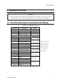
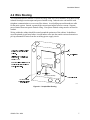
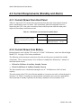
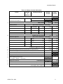
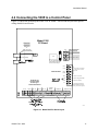
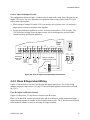
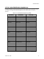
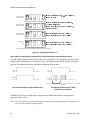
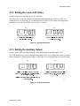
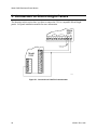
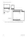
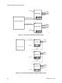
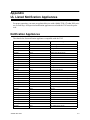
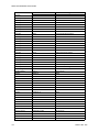
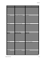
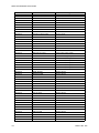
1. Introduction The Model 5395 is a notification and auxiliary power expander that provides up to 6 amps of regulated, 24 volt power for powering notification appliances and auxiliary devices. The 5395 provides its own AC power connection, battery charging circuit, and battery connections. Used with security and fire panels, the 5395 enables you to connect and distribute power to many more devices than your panel may normally allow. • Comparison to the Silent Knight Model 5295 The 5395 signal inputs operate the same way as the signal inputs on the Model 5295 Signal Power Expander. Two of the configurations described on page 5 are the same as the two configurations on the 5295. However, pay close attention to the output and input terminal numbers before replacing a Model 5295 with the Model 5395. The terminal assignments of inputs 1 and 2 are reversed on the 5395, and there are additional terminals on the 5395 that are not on the 5295 panel. • Input Configurations The 5395 has two optically isolated signaling inputs that provide the signal connection from the main control panel to the 5395 (see page 4 for more details). • Output Configurations The 5395 has four power-limited notification outputs that can be configured in various combinations of class A and Class B circuits (see page 5 for more details). • Auxiliary Power Configurations The 5395 has a dedicated, power-limited, auxiliary output that can be configured in two different ways. The auxiliary output can either be non-resettable (always on), or configured to switch off when the AC power goes off to conserve the battery standby power. When the auxiliary power is configured to switch off, there is a 30 second delay before the auxiliary power is turned off after the AC power goes off (see page 19 for more details). • Form C Trouble Relay The 5395 includes a general trouble relay that will de-energize for any trouble situation on the 5395 (see page 12 for more details). • Earth Fault Detection The 5395 monitors for earth faults to the system power or system ground. When detected, the system de-energizes the trouble relay and the input supervision relays (see page 28 for details). • ANSI Temporal Code The 5395 provides two configuration options that will drive outputs with the ANSI temporal code if the inputs are on constant (see page 18 for details). 150933 / Rev. 9/96 1 Model 5395 Distributed Power Module 2. UL Requirements When installed in accordance with NFPA 72 rules, the 5395 is listed to meet UL 1481 standards and can be connected to UL Listed devices suitable for local service. The 5395 is also listed to meet UL 864 standards and power limiting requirements. The 5395 is compatible with any UL listed control unit utilizing reverse polarity supervised notification outputs, using 24 VDC regulated outputs. 2 150933 / Rev. 9/96 Installation Manual 3. System Overview CAUTION Each output circuit is rated at 3 amps. DO NOT OVERLOAD. Overloading a circuit will cause it to shut down (power limit). The circuit will automatically reset once you remove the overload condition. 3.1 Terminal Descriptions and Electrical Ratings Table 3-1. Terminal Descriptions Terminal # Description Ratings TB1 1 2 3 AC (black“hot”) Earth Ground 120 VAC 60 Hz AC (white“neutral”) TB2 1 2 3 4 5 6 7 8 9 10 11 Auxiliary Power (-) Auxiliary Power (+) Notification 4 Output (-) Notification 4 Output (+) Notification 3 Output (-) Notification 3 Output (+) Notification 2 Output (-) Notification 2 Output (+) Notification 1 Output (-) Notification 1 Output (+) Normally Closed contact 12 13 14 15 16 17 18 19 Common Normally Open contact Input 2 Input 2 (-) Input 2 (+) Input 1 Input 1 (-) Input 1 (+) 150933 / Rev. 9/96 24 VDC 3.0 amps 24 VDC 3.0 amps Even though each output is rated for 3 amps, the 24 VDC 3.0 amps total current draw from the 4 outputs and the 24 VDC 3.0 amps auxiliary power must not exceed 6 amps of 24 VDC 3.0 amps notification power. 2.5 A @ 250 VAC or 2.5 A @ 30 VDC 9 - 30 VDC 9 - 30 VDC 3 Model 5395 Distributed Power Module 3.2 Signal Input Terminals Terminals 14 through 19 are polarized signal input terminals. They provide the signaling connection from the main panel to the 5395. See Figure 4-2 on page 11 for more details. Section 5 shows connections to specific Silent Knight fire and security panels. The main panel supervises its notification circuits used for communicating with the 5395 the same way it supervises ordinary notification circuits. The signal inputs on the 5395 monitor the polarity of the voltage coming from the main panel’s notification circuits to determine when to operate the notification circuits on the 5395. The 5395 emulates the trouble behavior of a normal notification circuit by breaking the EOL supervision current for internal or output trouble conditions on the 5395. Note that the 5395 will accurately sense the polarity of the main panel’s notification circuits to drive the outputs whether or not the supervision connection is intact. The following situations will disconnect the EOL supervision at the signal inputs and indicate a trouble condition: • • • • • Low AC power Low Battery condition Earth ground fault to the system power or system ground Auxiliary output power-limited condition EOL supervision trouble or power-limited condition at an output Trouble conditions will not necessarily occur for both inputs when the trouble is specific to a particular output. Only the signal input controlling the output circuit that is in trouble will indicate a trouble condition. Below are examples where both inputs do NOT indicate trouble for a trouble occurring at only one output circuit. Example 1: If input 1 controls all four outputs, a fault on any output will cause input 1 to indicate trouble. The fault does not affect input 2. Example 2: If input 1 controls outputs 1 and 2, and input 2 controls outputs 3 and 4, a fault condition on output 3 or 4 will cause input 2 to indicate trouble. The fault does not affect input 1. Note: Once the inputs are driven with forward polarity to activate the outputs, the main control panel will not be able to sense trouble conditions through its notification circuit connected to the 5395 input circuits. Use the 5395 trouble relay when it is necessary to monitor trouble conditions and active alarm conditions at the same time. Section 7 explains the significance of each trouble condition in more detail. 4 150933 / Rev. 9/96 Installation Manual 3.3 Notification Output Terminals Terminals 3 through 10 are the notification output terminals. Each of the four outputs is rated at 3 amps, though you can only draw a total of 6 amps from the 5395. The 5395 outputs are shortcircuit protected (power limited) according to UL 864 standards. Overcurrent indicators are yellow LEDs. The output voltage can vary depending on the load and input voltage. The four power-limited notification outputs can be configured as follows: • Four class B circuits • Two class A circuits • One class A and two class B circuits • Class B, ANSI temporal-coded circuits One or both 5395 signal inputs control the notification outputs, depending on the specific configuration setup. Possible configurations for the 5395 are: For Option: 1 2 3 4 5 6 7 8 These Inputs: Control These Outputs: Input 1 Input 1 or Input 2 Input 1 Input 2 Input 1 Input 2 Input 1 Input 1 All outputs Outputs 1, 2, 3, and 4 Outputs 1 and 2 Outputs 3 and 4 Output 1 Outputs 2, 3, and 4 Outputs 1-2 and 3-4 Outputs 1 and 2 Input 2 Input 1 Input 2 Input 1 Input 2 Outputs 3 and 4 Outputs 1-2 Outputs 3-4 Outputs 1-2 Outputs 3 and 4 As: Class B circuits Class B ANSI temporalcoded circuits Class B circuits Class B circuits Class B circuits Class B circuits Class A circuit pairs Class B ANSI temporalcoded circuits Class B circuits Class A circuit pair Class A circuit pair Class A circuit pair Class B circuits You can select which input controls which output, and which inputs are class A and class B using the 5-position DIP switch on the printed circuit board. Refer to page 17 for DIP switch settings. 150933 / Rev. 9/96 5 Model 5395 Distributed Power Module 4. Installation Before installing the 5395, the AC input must first be wired into the building’s main electrical power through the TB1 terminals (see page 11). Shut off the electrical power to the 5395, and then complete the general installation of the 5395 using the information in this section. 4.1 Mounting Mount the 5395 in locations that meet the following temperature and humidity requirements. Do not expose the 5395 panel to conditions outside of these ranges. Temperature 0o C-49o C (32o F-120o F) Humidity 10%-85% at 30o C (86o F) noncondensing When mounting on interior walls, use appropriate screw anchors in plaster. When mounting on concrete, especially when moisture is expected, first attach a piece of 3/4-inch plywood to the concrete surface. Attach the 5395 to the plywood. 6 150933 / Rev. 9/96 Installation Manual 4.2 Wire Routing To avoid induced noise (transfer of electrical energy from one wire to another), keep input wiring isolated from high current output and power-limited wiring. Induced noise can interfere with telephone communication or even cause false alarms. Avoid pulling one multiconductor cable for the entire system. Instead, separate high current input/output from low current. Separate power-limited from non-power-limited wiring. Non-power-limited wiring must be enclosed in conduit. Wiring within the cabinet should be routed around the perimeter of the cabinet. It should not cross the printed circuit board where it could induce noise into the sensitive microelectronics or pick up unwanted RF noise from the switching power supply circuit. DXUbU ]ecd RU Qd \UQcd !$Y^SX c`QSY^W RUdgUU^ XYWX Q^T \_g D_ 13 f_\dQWUc ^_^`_gUb\Y]YdUT 1\\ gYbY^W ]ecd RU gYdXY^ dXU bQ^WU _V !"!( 1]UbYSQ^ GYbU 5395 Board 7QeWU 1G7 >_^ `_gUb \Y]YdUT gYbY^W ]ecd RU be^ Y^ S_^TeYd cU`QbQdU\i Vb_] 1 10 11 19 `_gUb\Y]YdUT gYbY^W Battery cables (non-power-limited) D_ S_^db_\ `Q^U\ D_ 1EH `_gUb Q^T ^_dYVYSQdY_^ SYbSeYdc `_gUb \Y]YdUT wirerout Figure 4-1. Sample Wire Routing 150933 / Rev. 9/96 7 Model 5395 Distributed Power Module 4.3 Current Requirements (Standby and Alarm) 4.3.1 Current Drawn From Host Panel Table 4-1 shows the 5395 current draw requirements from the main control panel when the panel’s notification circuit is in alarm. The current draw from the main panel when it is supervising the 5395 is the same current draw that would be present when the main panel supervises an ordinary notification circuit. Table 4-1. 5395 Alarm Current Drawn From Main Panel Alarm Current (for typical voltages) drawn from main panel’s notification circuits. Panel Voltage Current 12 VDC 6.5 mA 24 VDC One input circuit: Both input circuits: 15 mA 30 mA 4.3.2 Current Drawn from Battery Backup batteries used with the 5395 must be UL listed 7 AH batteries, such as the Silent Knight Model 6712. See page 16 for battery installation. The following is the maximum current draw from the auxiliary power terminals for standby calculations. These currents assume 24 or 60 hours of standby time followed by 5 minutes of maximum alarm current. • • 195 mA for 24 Hours of Auxiliary Standby Current 39 mA for 60 Hours of Auxiliary Standby Current The above numbers were calculated assuming the use of 7 AH batteries at 100% of rated capacity. The total current of the 5395, plus all items attached to it, must not exceed 6 A when the panel is in alarm. Use Table 4-2 on page 9 to ensure that the current does not exceed 6 A and, that the desired amount of standby is possible for the battery intended to be used with the 5395. 8 150933 / Rev. 9/96 Installation Manual Table 4-2. Battery Calculation Worksheet Device For each device use this formula: Number of Devices Current per Device This column 5395 Distributed Power Module (Current draw from battery) 1 X This column Standby: Standby Current = 75 mA Alarm: 5395 Current B Notification appliances C Current per number of devices. 75 mA 100 mA A Auxiliary Devices Alarm Current 100 mA 75 mA Refer to device manual for current ratings. Alarm/Standby mA mA mA Alarm/Standby mA mA mA Alarm/Standby mA mA mA Alarm/Standby mA mA mA Auxiliary Devices Current mA mA Refer to device manual for current ratings. Alarm: mA 0 mA mA Alarm: mA 0 mA mA Alarm: mA 0 mA mA Alarm: mA 0 mA mA Notification Appliances Current 0 mA mA mA mA A D Total current ratings of all devices in system (line A + line B + line C) E Total current ratings converted to amperes (line D x .001): A F Number of standby hours (24 or 60 for NFPA 72, Chapter 1, 1-5.2.5). H G Multiply lines E and F. H Alarm sounding period in hours. (For example, 5 minutes = .0833 hours.) Total standby AH AH H I Multiply lines E and H. J Add lines G and I. Total standby and alarm AH AH K Multiply line J by 1.20. (20% extra insurance to meet desired performance) Total ampere-hours required AH 150933 / Rev. 9/96 100 mA Total alarm AH AH 9 Model 5395 Distributed Power Module (This page left blank in case of removal.) 10 150933 / Rev. 9/96 Installation Manual 4.4 Connecting the 5395 to a Control Panel Figure 4-2 shows the general layout of the 5395 PC board. This section also provides specific wiring details for accessories. Model 5395 PC Board Batteries Model 6712 Supervised or other 12V, 7AH equivalent batteries Supervised AC TB1 (White) Neutral Red F1 BATT. 1 Ground BATT. + U10 Red (P/N 140694) BATT. 2 Black (Black) 120 VAC In The AC input must be connected to unswitched 120 VAC 60 hz output. BATT. - AC OUT1 On means overcurrent, open circuit, or short circuit. OUT2 Fault Indicators OUT3 OUT4 On means overcurrent AUX On means earth ground fault FLT Outputs are power-limited according to UL 864 standards AUX 1 2 - + 1 2 3 4 5 OUT3 OUT2 OUT1 3 5 7 9 6 8 On means low battery AC OUT4 4 BATT DIP Switch 10 Trouble Relay 11 12 13 INPUT2 14 15 16 On (green LED) means AC is present (OFF means there is no AC power to the panel) INPUT1 17 18 TB2 19 N.C. COM N.O. 6_b E< \YcdUT QeTYR\U Q\Qb] Y^TYSQd_bc CUU DQR\U $# V_b Q``b_fUT 6_b S_^^USdY_^ d_ S_^db_\ `Q^U\ ^_dYVYSQdY_^ Q``\YQ^SUc >_^S_TUT 5395bd Figure 4-2. Model 5395 PC Board Layout 150933 / Rev. 9/96 11 Model 5395 Distributed Power Module Consult your control panel manual for specific wiring information on the control panel being used. If you are using a Silent Knight control panel, see page 20 for connections. 4.4.1 Trouble Relay The 5395 board has a Form C trouble relay built into terminals 11-13. The relay provides a normally open and a normally closed contact, both of which are rated at 2.5A. The trouble relay will deactivate under any trouble condition. A typical application of the trouble relay is to connect the 5395 normally closed (N.C.) contacts in series with the EOL supplied with the fire panel. This will cause a trouble on the fire panel when the 5395 opens its trouble contacts. Note: The N.C. contact is the relay contact that is closed when the 5395 has power and there are no trouble conditions. Model 5395 Trouble Relay 9 10 11 12 13 14 15 16 17 18 19 N.C. COM N.O. UL listed EOL (supplied with fire panel) 18 19 20 Model 5207 trouble Figure 4-3. Trouble Relay Connection Example 4.4.2 Class A Supervised Wiring Figure 4-4 shows how to wire for Class A input and output supervision. Use in/out wiring methods for proper supervision. (See page 15 for notification appliances that must be used with the 5395.) Class A Output Notification Circuits The configuration shown in Figure 4-4 shows two, 3-amp devices wired as class A circuits. When you are using the outputs as class A circuits, loop the wiring back to the corresponding circuit pair. For class A wiring, no external EOL is necessary since it is built into the 5395 board. 12 150933 / Rev. 9/96 Installation Manual Class A Supervised Input Circuits The configuration shown in Figure 4-4 shows class A supervised wiring from a fire panel to the Model 5395 board. Pay close attention to the polarities when wiring a panel to the 5395 and follow these requirements: • When wiring to terminal 18 on the 5395, you must use two separate wires. Do not loop a single wire or twist two conductor wires together. • Do not use notification appliances on class A circuits connected to a 5395 for input. The 5395 will detect voltage across the input circuits, but is not designed to pass the added current load from notification appliances. Model 5395 AUX 1 2 OUT4 3 4 OUT3 5 6 OUT2 7 8 OUT1 9 10 Trouble Relay 11 12 Input 2 13 14 15 16 two separate wires 18 Input 1 17 18 19 correct - + Supervised Notification Circuits looping single wire twisting two wires 18 18 Class A notification outputs from fire panel Class A + In Out + Incorrect classain Figure 4-4 Class A Supervised Input/Output Connections 4.4.3 Class B Supervised Wiring Figure 4-5 shows how to wire for Class B input and output supervision. Use in/out wiring methods for proper supervision. (See page 15 for notification appliances that can be used with the 5395.) Class B Output Notification Circuits Figure 4-5 shows four, 1.5 amp devices wired as class B circuits. Place a 4.7k ohm EOL resistor (provided) at the end of each loop to enable notification output supervision when using all outputs as class B notification circuits. The 4.7k EOLs must be wired to the terminals whether or not you are using all output terminals. 150933 / Rev. 9/96 13 Model 5395 Distributed Power Module Class B Supervised Input Circuits Figure 4-5 shows class B supervised wiring from a fire panel to the Model 5395 board. Use an EOL resistor as shown to enable notification input supervision. Some panels use EOLs that have a different value than the 4.7k ohm EOL resistor used by the 5395. In this case, the EOL must be UL listed for the fire panel (not the 5395). Model 5395 OUT4 3 4 AUX 1 2 - OUT3 5 6 OUT2 7 8 OUT1 9 10 Trouble Relay 11 12 Input 1 Input 2 13 14 15 16 17 18 19 + Supervised Notification Circuits Class B notification output from fire panel EOL (must be UL listed for the fire panel) Class B Model 7628 4.7k EOL Model 7628 4.7k EOL + classbin Figure 4-5. Class B Supervised Input/Output Connections 14 150933 / Rev. 9/96 Installation Manual 4.5 UL Listed Notification Appliances For proper operation, you must use polarized devices with a Model 7628 4.7k ohm EOL resistor on each loop. All supervised notification appliances used with the Model 5395 must be polarized. Table 4-3. UL Listed Notification Appliances (24 VDC) Manufacturer Faraday Federal Signal Federal Signal Gentex Gentex Gentex System Sensor System Sensor System Sensor System Sensor System Sensor System Sensor System Sensor Wheelock Wheelock Wheelock Wheelock Wheelock Wheelock Wheelock Wheelock Wheelock Wheelock Wheelock Wheelock Wheelock Wheelock Wheelock Wheelock Wheelock Wheelock Wheelock Wheelock Wheelock Wheelock Wheelock Wheelock Wheelock Wheelock Wheelock Model Number 6126B-U-14-24VDC VALS 450-D HG124 SHG24L SHG24H MA/SS/24I MASS2415ADA MASS2475ADA MASS24110ADA SS2415ADA SS2475ADA SS24110ADA 34T-24-R 46T-G10-24-R 7001T-24-W-FR 7002T-24-W-FR E-7025-WH-24-VF-R E-7025-WH-24-VF-W E-7070-WH-24-VF-R E-7070-WH-24-VF-W E-9025-WH-24-CF-W E-9070-WH-24-CF-W E-7025-WM-24-VF-R E-7025-WM-24-VF-W E-7070-WM-24-VF-R E-7070-WM-24-VF-W E-7025-WS-24-VF-R E-7025-WS-24-VF-W E-7070-WS-24-VF-R E-7070-WS-24-VF-W E-9025-WS-24-CF-W E-9070-WS-24-CF-W ET-1010-WS-24 HF-R ET-1070-WS-24-VF-R ET-1080-WS-24-VF-R ET-1090-WS-24-CF-W ET-1070-WM-24-VF-R ET-1070-WM-24-VF-W ET-1080-WM-24-VF-R Device Type Horn/Strobe Horn/Strobe Horn Horn Horn Strobe Horn Strobe Horn/Strobe Horn/Strobe Horn/Strobe Horn/Strobe Strobe Strobe Strobe Alarm Horn Bell Strobe Horn Strobe Horn Strobe Speaker Strobe Speaker Strobe Speaker Strobe Speaker Strobe Speaker Strobe Speaker Strobe Speaker Strobe Speaker Strobe Speaker Strobe Speaker Strobe Speaker Strobe Speaker Strobe Speaker Strobe Speaker Strobe Speaker Strobe Speaker Strobe Speaker Strobe Speaker Strobe Speaker Strobe Speaker Strobe Speaker Strobe Speaker Strobe Speaker continued on next page 150933 / Rev. 9/96 15 Model 5395 Distributed Power Module continued from previous page Manufacturer Wheelock Wheelock Wheelock Wheelock Wheelock Wheelock Wheelock Wheelock Wheelock Wheelock Wheelock Wheelock Wheelock Wheelock Wheelock Wheelock Wheelock Wheelock Wheelock Wheelock Model Number ET-1080-WM-24-VF-W EW-EH1-R MB-G6-24-R MB-G10-24-R MBS-G6-24-W-HF-R MBS-G10-24-W-HF-R MIZ-24-R MIZ-24-W MIZ-24-WS-VF-R MIZ-24-WS-VF-W MIZ-24-WS-VF-R MT-12/24-R MT-24-WM MT-24-WM-VF-R Series HS Series LS V7001T-24-W-FR WST-24-FR WS1T-24-FR WS3T-24-FR Device Type Strobe Speaker Slow Whoop Horn Motor Bell Motor Bell Motor Bell with Strobe Motor Bell with Strobe Mini-Horn Mini-Horn Mini-Horn Mini-Horn/Strobe Mini-Horn/Strobe Strobe Horn Strobe Horn Strobe Horn Strobes Strobes Strobe Horn Strobe Strobe Strobe 4.6 Battery Connection You must use two backup batteries with the 5395. Use 12 VDC, 7 AH gel cell batteries, such as the Silent Knight Model 6712. It is recommended that you replace the batteries every five years. The following steps and diagram explain how to connect the batteries. 1. Connect the black wire to the negative (-) side of battery #2. 2. Connect the jumper wire provided (P/N 140694) from the positive (+) side of battery #2 to the negative side of battery #1. 3. Connect the red wire to the positive (+) side of battery #1. Model 5395 Red Model 6712 (Supervised) BATT. 1 Red BATT. 2 Jumper (P/N 140694) BATT. + BATT. - Black battery Figure 4-6. Battery Connection 16 150933 / Rev. 9/96 Installation Manual 4.7 DIP Switch Settings A 5-position DIP switch on the 5395 board allows you to select the following: • • • • • How long the 5395 will wait before indicating a loss of AC. Which input (Input 1 or Input 2) will control the notification outputs. Which outputs to wire as class A and class B. Auxiliary power state. Which outputs to operate as steady outputs or ANSI temporal. Refer to Figure 4-2 on page 11 for the location of the DIP switch on the 5395 board. 4.7.1 Selecting the Input/Output Configuration Figure 4-7 shows the position of each switch on the DIP switch for various input and output configurations. The position of switch 4 and 5 do not affect the relationship of inputs to outputs. Note: The 5395 checks switches 1, 2, and 3 only when powering up the 5395. If you change these switch settings, you must remove both the AC power and the battery to force the 5395 to recognize the new switch settings. 9^`ed ! S_^db_\c Q\\ _ed`edc S\Qcc 2 S w itch 1 -3 OFF 9^`ed " ^_d ecUT 1 2 3 4 5 9^`ed ! _b 9^`ed " S_^db_\c Q\\ _ed`edc S\Qcc 2 * S w itc h 1 -2 O F F S w itc h 3 O N gYdX 1>C9 dU]`_bQ\ _ed`ed `QddUb^ 1 2 3 4 5 9^`ed ! S_^db_\c _ed`edc ! Q^T " S\Qcc 2 S w itch 1 , 3 O F F S w itch 2 O N 9^`ed " S_^db_\c _ed`edc # Q^T $ S\Qcc 2 1 2 3 4 5 9^`ed ! S_^db_\c _ed`ed ! S\Qcc 2 S w itc h 1 O F F S w itc h 2 -3 O N 9^`ed " S_^db_\c _ed`edc " # Q^T $ S\Qcc 2 1 2 3 4 5 * S e e th e fo llo w in g in fo rm a tio n a b o u t A N S I te m p o ra l-c o d e d o u tp u ts 150933 / Rev. 9/96 17 Model 5395 Distributed Power Module 9^`ed ! S_^db_\c _ed`edc ! " # Q^T $ S\Qcc 1 S w itch 1 O N S w itch 2 -3 O F F 9^`ed " ^_d ecUT 1 2 3 4 5 9^`ed ! S_^db_\c _ed`edc ! Q^T " Qc S\Qcc 2 * S w itc h 1 ,3 O N S w itch 2 O F F 1>C9 dU]`_bQ\ _ed`edc 9^`ed " S_^db_\c _ed`edc # Q^T $ Qc S\Qcc 2 1 2 3 4 5 S_^cdQ^d _ed`edc 9^`ed ! S_^db_\c _ed`edc ! Q^T " S\Qcc 1 S w itch 1 -2 O N S w itch 3 O F F 9^`ed " S_^db_\c _ed`edc # Q^T $ S\Qcc 1 1 2 3 4 5 S w itc h 1 -3 ON 9^`ed ! S_^db_\c _ed`edc ! Q^T " S\Qcc 1 9^`ed " S_^db_\c _ed`edc # Q^T $ S\Qcc 2 1 2 3 4 5 dips * S e e th e fo llo w in g in fo rm a tio n a b o u t A N S I te m p o ra l-c o d e d o u tp u ts Figure 4-7. Setting DIP Switches 1-3 Special Note for Input/Output Configurations That Select ANSI Temporal-Coded Outputs The DIP switch settings marked with an asterisk (*) in Figure 4-7 are designed to produce ANSI temporal-coded outputs from a constant on input. The figures shown below compare the output patterns of configurations before and after the addition of this feature. Inpu t In p u t O utp ut O u tp u t 4 se c . .5 se c . o n , .5 s e c . o ff, .5 se c. o n , .5 s e c . o ff, .5 se c. o n , 1 .5 se c. o ff (re p e a t) Standard 5395 Input to Output Relationship Input/Output Relationship for ANSI Temporal-coded Options With this new feature, a steady signal can produce the pattern shown above for panels not previously able to do so. Note: The 5395 can also produce other temporal patterns if the patterns appear at the inputs for the non-ANSI temporal configurations. 18 150933 / Rev. 9/96 Installation Manual 4.7.2 Setting the Loss of AC Delay Normal selection for reporting loss of AC is 6 hours. The ON position is for test purposes only and the normal position for switch 4 is OFF. For testing the Low AC reporting, you can temporarily turn switch 4 ON without removing power. Remember to turn the switch OFF when testing is complete. ON 1 OFF 3 2 1 5 4 13 db_eR\U S_^TYdY_^c gY\\ _SSeb Y]]UTYQdU\i 3 2 4 5 DXU %#)% gY\\ TU\Qi bU`_bdY^W Q^ X_ebc 13 db_eR\U V_b & X_ebc dips4 Figure 4-8. Setting DIP Switch 4 4.7.3 Setting the Auxiliary Output Switch 5 on the DIP switch determines how the auxiliary power operates on the 5395. The 5395 checks switch 5 only when powering up the 5395. If you change this switch, you must remove both the AC power and the battery to force the 5395 to recognize the new switch setting. ON 1 2 3 OFF 4 1ehY\YQbi `_gUb gY\\ cXed T_g^ # 5 cUS_^Tc 1 2 3 4 5 1ehY\YQbi `_gUb Yc Q\gQic _^ Q^T gY\\ QVdUb 13 `_gUb Yc \_cd Q^T dXU e^Yd Yc be^^Y^W ^_d cXed T_g^ gXU^ dXU cicdU] \_cUc _^ dXU RQS[e` RQddUbi 13 `_gUb 1ehY\YQbi `_gUb bUcd_bUc Y]]UTYQdU\i gXU^ dXU 13 `_gUb bUcd_bUc dips5 Figure 4-9. Setting DIP Switch 5 150933 / Rev. 9/96 19 Model 5395 Distributed Power Module 5. Connection to Silent Knight Panels The drawings in this section show you how to connect the 5395 to compatible Silent Knight panels. See panel installation manuals for more information. Model 5395 Trouble Relay 9 10 11 12 Input 2 13 14 15 16 Input 1 17 18 19 Model 7628 4.7k EOL 22 Model 5104 7 21 20 19 18 8 17 9 16 10 15 11 14 12 13 53955104 Figure 5-1. Connection to 5104 Fire Communicator 20 150933 / Rev. 9/96 Installation Manual Model 5395 Trouble Relay 9 Model 5204 or 5204PL 3 4 5 10 11 12 Input 2 13 12 14 Input 1 15 16 17 18 19 Model 7628 4.7k EOL 11 10 9 6 8 7 53955204 Figure 5-2. Connection to 5204 Fire Control/Communicator Model 5395 Trouble Relay 9 10 11 12 Input 2 13 14 15 16 Input 1 17 18 19 32 31 Model 7628 4.7k EOL 30 29 Model 5207 28 27 53955207 Figure 5-3. Connection to 5207 Fire Control/Communicator 150933 / Rev. 9/96 21 Model 5395 Distributed Power Module 5395 7 8 11 4160 17 18 19 1 - + - + 6 Model 7630 15k EOL Notification Devices 3 A per output (6 A max.) 7 22 6 1 4720 Model 7628 4.7k EOL Zones Supervision 23 34* 38 * Term. 34 (Zone 12) used as an example. 53954720 Figure 5-4. Connection to 4720 Control/Communicator and 4160 Supervision Module 22 150933 / Rev. 9/96 Installation Manual 6. Sample Applications The drawings in this section show various 5395 configurations, including daisy-chaining. 6.1 Notification Power Applications Notification Circuit Local Fire Control Input 1 Output 1 Output 2 Output 3 Output 4 Model 5395 120 VAC 1 3 2 4 5 config1 Figure 6-1. Input 1 Activates All Four Outputs Notification Circuit Notification Circuit Local Fire Control Input 1 Input 2 Model 5395 Output 1 Output 2 Output 3 Output 4 120 VAC 1 2 3 4 5 config2 Figure 6-2. Input 1 Activates Outputs 1 and 2; Input 2 Activates Outputs 3 and 4 150933 / Rev. 9/96 23 Model 5395 Distributed Power Module 120 VAC Output 1 Output 2 Output 3 Output 4 Model 5395 Notification Circuit 1 2 3 4 5 Input 1 Local Fire Control Notification Circuit Input 1 Output 1 Output 2 Output 3 Output 4 Model 5395 120 VAC 1 2 3 4 5 config3 Figure 6-3. One Control Activating Two Model 5395s Notification Circuit Input 1 Output 1 Output 2 Output 3 Model 5395 120 VAC 1 2 3 4 5 Local Fire Control Output 4 Input 1 Output 1 Output 2 Output 3 Model 5395 120 VAC 1 3 2 4 5 Output 4 Input 1 Model 5395 Output 1 Output 2 Output 3 Output 4 120 VAC 1 2 3 4 5 config4 Figure 6-4. One Control Activating Three Model 5395s in Series 24 150933 / Rev. 9/96 Installation Manual O utput O utput O utput O utput 1 2 0 VA C M odel 5395 In p u t 1 1 3 2 4 1 2 3 4 O u tp u ts A ctive w h e n L o ca l C o n tro l N o tifica tio n C irc u it 1 A c tiv a te s 5 O u tp u t 1 N otific a tio n C irc u it 1 N o tifica tio n C irc u it 2 In p u t 1 In p u t 2 O u tpu t 2 O u tpu t 3 M odel 5395 1 2 0 VA C 1 L o ca l F ire C on tro l 3 2 4 5 O u tp u ts A ctive w h e n L o c a l C o n tro l N o tific a tio n C irc u it 2 A c tiva te s O u tp u t 4 In p u t 1 O utput O utput O utput O utput M odel 5395 1 2 3 4 1 2 0 VA C 1 2 3 4 5 config5 Figure 6-5. Each Control Signal Circuit Activates Five Output Circuits 150933 / Rev. 9/96 25 Model 5395 Distributed Power Module 6.2 Non-Resettable Power Application The 5395 provides a dedicated 3-amp auxiliary power output that you can select as non-resettable (output is always on). See Section 4.7.3 for setting the auxiliary power. If you need more than 3 amps, wire the inputs as shown in Figure 6-6. M od el 53 95 DXYc gYbY^W `b_fYTUc e` d_ % Q]`c ]Qh AUX 1 2 _V S_^dY^e_ec ^_^ OUT1 3 4 OUT2 5 6 OUT3 7 8 OUT4 9 10 T ro u b le R elay 11 1 2 In pu t 2 13 14 15 16 In p u t 1 17 18 19 bUcUddQR\U `_gUb TYcdbYRedUT Q]_^W - + dXU V_eb _ed`edc >_dU* ]QhY]e] SebbU^d Yc 1\\ V_eb _ed`edc gY\\ RU ^_^bUcUddQR\U `_gUb # Q]`c `Ub _ed`ed Ce`UbfYcU db_eR\U S_^TYdY_^c ecY^W dXU db_eR\U bU\Qi res e t Figure 6-6. Auxiliary Output Wiring for Non-Resettable Power 6.3 Door Holder Application In a typical door holder application, the door holder power must be released to close all fire doors under the following conditions: • • Any active alarm condition. AC power is no longer present (to conserve backup battery power). To close the fire doors in these situations, wire an N.C. programmable relay from the fire panel in series with the auxiliary power to the door holders as shown in Figure 6-7. The circuit shown in Figure 6-7 will provide up to 3 amps of door holder power. (See Section 6.2 if you need more than 3 amps of auxiliary power.) The power in this example is released when AC power is off for 30 seconds or more, or when the relay from the fire panel becomes open. You would have to use the equivalent of a programmable relay from a fire panel that is programmed to open under alarm conditions. See page 19 for selecting auxiliary power options. Model 5395 Model 5207 AUX 1 2 Door Holders door Figure 6-7. Door Holder Wiring Example 26 150933 / Rev. 9/96 Installation Manual 7. Troubleshooting Light-emitting diodes (LEDs) indicate fault conditions. This section describes the LED states and provides trouble condition details. 7.1 LEDs The eight LEDs indicate a fault condition in one of the circuits (either outputs 1 through 4, auxiliary power, earth fault, low AC, or battery). A fault condition in the LED's corresponding circuit will turn on the LED (labeled on the board). Their functions are as follows: LED Color Description OUT1 Yellow When ON, output circuit 1 is in trouble or in an overcurrent state. OUT2 Yellow When ON, output circuit 2 is in trouble or in an overcurrent state. OUT3 Yellow When ON, output circuit 3 is in trouble or in an overcurrent state. OUT4 Yellow When ON, output circuit 4 is in trouble or in an overcurrent state. AUX Yellow When ON, the auxiliary power output is in an overcurrent state. FLT Yellow When ON, an earth ground fault on the unit exists. BATT Yellow When ON, a low battery condition exists. AC Green When OFF, there is no AC power to the unit. Under normal conditions, this LED is ON to indicate the presence of AC power. See page 11 for locations of LEDs. 150933 / Rev. 9/96 27 Model 5395 Distributed Power Module 7.2 Trouble Conditions Trouble Condition What Happens Low AC Input 1 and Input 2 supervision loops open after a 6 hour delay. (AC input voltage is low or off for 6 hours or longer.) The green AC LED turns off as soon as low AC or loss of AC occurs (does not wait 6 hours). The trouble relay is de-energized after a 6 hour delay. The trouble restores within 1 minute of the AC voltage restoring to a normal level. Low Battery Input 1 and Input 2 supervision loops open. The yellow “BATT” LED turns on. (Battery voltage is less than 21.4 VDC.) The trouble relay is de-energized. Earth Ground Fault Input 1 and Input 2 supervision loops open. The yellow “FLT” LED turns on. (The earth terminal is connected to one of the positive or negative terminals on the output or auxiliary output circuits.) The trouble relay is de-energized. Power Limit At AUX Power disconnects at the AUX terminal. Input 1 and Input 2 supervision loops open. The yellow “AUX” LED turns on. The trouble relay is de-energized. (Current draw at the auxiliary power terminals is exceeding 3.0 amps.) The trouble restores when battery voltage is greater than 22.4 VDC. The trouble restores when the fault between the earth ground and one of the output circuit terminals is removed. The trouble restores when the overcurrent condition no longer exists. When a circuit goes into a power limited state, it will reverse the polarity of the voltage at the terminals and verify the load. If it is more than 1k ohms, the power limit will self-restore. This does not automatically occur for some devices typically connected to auxiliary power. Power limit conditions do not restore in reverse polarity monitoring if the devices are not polarized (for example, some door holder devices). To allow automatic restores for power-limited auxiliary circuits, it is recommended that all non-polarized devices be polarized using a diode in series with each device. Power-limited OUTPUT (Current draw at an output terminal is exceeding 3.0 amps.) Power at the OUTPUT is disconnected. Input 1 and Input 2 supervision loops open. The corresponding yellow LED turns on. The trouble relay is de-energized. The trouble restores when the overcurrent condition no longer exists. EOL supervision trouble Input 1 and Input 2 supervision loops open. Corresponding yellow LED turns on. (Equivalent resistance of the EOL resistor is outside the range 2k - 10k.) The trouble relay is de-energized. 28 Trouble restores if an EOL within (2k-10k) appears at the output terminals. 150933 / Rev. 9/96 Appendix UL Listed Notification Appliances For proper operation, you must use polarized devices with a Model 7628 4.7k ohm EOL resistor on each loop. All supervised notification applicances used with the 5395 must be polarized. Notification Appliances The chart below lists notification appliances compatible with the 5395. Manufacturer Faraday Faraday Faraday Faraday Faraday Faraday Faraday Faraday Faraday Faraday Faraday Faraday Faraday Faraday Faraday Faraday Faraday Faraday Faraday Faraday Faraday Faraday Faraday Faraday Faraday Faraday Faraday Faraday Faraday Faraday 150933 / Rev. 9/97 Model 446 476 477 5333 5336 5337 5338 5343 5346 5347 5348 5373 5376 5377 5378 5383 5386 5387 5388 5405 5508 5509 5510 5511 5512 5516 5517 5518 5519 5521 Type Vibrating Bell Vibrating Bell Single Stroke Bell Multi-Tone Horn) Multi-Tone Horn/Strobe Multi-Tone Horn/Strobe Multi-Tone Horn/Strobe Single Tone Horn/Strobe Electronic Horn with Strobe Electronic Horn with Strobe Single Tone Horn/Strobe 8-Tone Horn/Strobe 8-Tone Horn/Strobe 8-Tone Horn/Strobe 8-Tone Horn/Strobe 8-Tone Horn/Strobe with Sync Strobe 8-Tone Horn/Strobe with Sync Strobe 8-Tone Horn/Strobe with Sync Strobe 8-Tone Horn/Strobe with Sync Strobe Sync Control Unit Single Gang Sync Strobe Strobe Strobe Strobe Strobe Strobe Strobe Strobe Strobe 4” Square Sync Strobe A-1 Model 5395 Distributed Power Module Manufacturer Faraday Faraday Faraday Faraday Faraday Faraday Faraday Faraday Faraday Faraday Faraday Faraday Faraday Faraday Faraday Faraday Faraday Faraday Faraday Faraday Faraday Faraday Faraday Federal Signal Federal Signal Gentex Gentex Gentex Gentex Gentex Gentex Gentex Gentex Gentex Gentex Gentex Gentex Gentex Gentex System Sensor System Sensor System Sensor System Sensor System Sensor System Sensor A-2 Model 5522 6120 6140 6223 6226 6227 6228 6243 6244 6245 6246 6247 6248 6300 6301 6302 6310 6311 6312 6320 6321 6322 6380 450 VALS GX90-4 GXS-4-15-1 GXS-4-1575 GX90S-4-15 GX90S-4-1575 HG124 SHG24-1575 SHG24-15 GMH-24-X GMS-24-X GMS-24-X G0T24 G0S24-X WGMS-24-X MASS241 MASS24110ADA MASS2415ADA MASS2475ADA SS24110ADA SS2415ADA Type 4” Square Sync Strobe Horn Horn Horn Horn/Strobe Horn/Strobe Horn/Strobe Electron-Mechanical Horn Electron-Mechanical Horn Electron-Mechanical Horn Electron-Mechanical Horn/Strobe Electron-Mechanical Horn/Strobe Electron-Mechanical Horn/Strobe Mini-Horn Mini-Horn Mini-Horn Mini-Horn/Strobe/Strobe Mini-Horn/Strobe/Strobe Mini-Horn/Strobe/Strobe Sync Mini Horn/Strobe Sync Mini Horn/Strobe Mini Horn/Sync Strobe 8-Tone Electronic Signal Horn Horn/Strobe Horn Strobe Strobe Horn Horn Horn Horn/Strobe Horn/Strobe Horn Horn/Strobe Horn/Strobe Horn Horn Horn/Strobe Horn/Strobe Horn/Strobe Horn/Strobe Horn/Strobe Strobe Strobe 150933 / Rev. 9/97 Appendix Manufacturer System Sensor System Sensor System Sensor System Sensor System Sensor Wheelock Wheelock Wheelock Wheelock Wheelock Wheelock Wheelock Wheelock Wheelock Wheelock Wheelock Wheelock Wheelock Wheelock Wheelock Wheelock Wheelock Wheelock Wheelock Wheelock Wheelock Wheelock Wheelock Wheelock Wheelock Wheelock Wheelock Wheelock Wheelock Wheelock Wheelock Wheelock Wheelock Wheelock Wheelock Wheelock Wheelock Wheelock Wheelock Wheelock 150933 / Rev. 9/97 Model SS2475ADA PS2415ADA PS241575ADA PS24110ADA PS2475ADA 46T-G4-24-R 46T-G6-24-R 46T-G10-24-R 46T-G6-24-WS-24-HF-R 46T-G10-24-WS-24-HF-R 46T-G6-24-WH-24-HF-R 46T-G10-24-WH-24-HF-R 7001T-12\24-W-FR 7002T-12\24-W-FR AES-DL1-R AES-EL1-R AES-DL1-WS-24-VF-R AES-EL1-WS-24-VF-R AES-DL1-WH-24-VF-R AES-EL1-WH-24-VF-R AES-DL1-WM-24-VF-R AES-EL1-WM-24-VF-R AH-24-R AMT-12\24-R AMT-24-LS-VFR AMT-24-LSM-VFR AMT-24-IS-VFR AS-2415-VFR AS-241575-VFR AS-2430-VFR AS-2475-VFR AS-24110-HFR SM-12\24-R DSM-12\24-R CF-BF1 CF-BF1-R CH-CF1 CH-CF1-R CH-CF1-W CH-DF1 CH-DF1-R CH-BF1-WS-24-HF-R CH-CF1-LS-24 CH-CF1-MS-24 CH-CF1-IS-24 Type Strobe Mini-Horn/Strobe Mini-Horn/Strobe Mini-Horn/Strobe Mini-Horn/Strobe Bell Bell Bell Strobe/Bell Strobe/Bell Strobe/Bell Strobe/Bell Strobe Horn Strobe Horn Multitone Horn Multitone Horn Multitone Horn Multitone Horn Multitone Horn Multitone Horn Multitone Horn Multitone Horn Horn Strobe Horn Strobe Horn Strobe Horn Strobe Horn Strobe Horn Strobe Horn Strobe Horn Strobe Horn Strobe Horn Strobe Horn Controller Strobe Horn Controller Chime Chime Chime Chime Chime Chime Chime Strobe Chime Strobe Chime Strobe Chime Strobe Chime A-3 Model 5395 Distributed Power Module Manufacturer Wheelock Wheelock Wheelock Wheelock Wheelock Wheelock Wheelock Wheelock Wheelock Wheelock Wheelock Wheelock Wheelock Wheelock Wheelock Wheelock Wheelock Wheelock Wheelock Wheelock Wheelock Wheelock Wheelock Wheelock Wheelock Wheelock Wheelock Wheelock Wheelock Wheelock Wheelock Wheelock Wheelock Wheelock Wheelock Wheelock Wheelock Wheelock Wheelock Wheelock Wheelock Wheelock Wheelock Wheelock Wheelock A-4 Model CH-CF1-LS-24-CFW CH-CF1-MS-24-CFW CH-CF1-IS-24-CFW CH-CF1-WS-24-CF-W CH-DF1-LS-24 CH-DF1-MS-24 CH-DF1-IS-24 CH-DF1-LS-24-VFR CH-DF1-LSM-24-VFR CH-DF1-MS-24-VFR CH-DF1-IS-24-VFR CH-DF1-WM-24-VFR CH-DF1-WS-24-VF-R DSM-12/24 EH-DL1-R EH-EL1-R Electronic Horn EHS-DL1-W-VF-R EHS-EL1-W-VF-R EH-DL1-WS-24-VF-R EH-EL1-WS-24-VF-R EH-DL1-WH-24-VF-R EH-EL1-WH-24-VF-R EH-DL1-WM-24-VF-R EH-EL1-WM-24-VF-R HSW-24-HFR HS2W-24-HFR HSPW-24-HFR IS-24-VFR IS1-24-VFR IS3-24-VFR ISP-24-HFR LS-24-VFR LS1-24-VFR LS3-24-VFR LSP-24-HFR LSM-24-VFR LS1M-24-VFR LS3M-24-VFR LSPM-24-VFR MS-24-VFR MS1-24-VFR MS3-24-VFR MSP-24-HFR MB-G6-24-R MB-G10-24-R Type Strobe Chime Strobe Chime Strobe Chime Strobe Chime Strobe Chime Strobe Chime Strobe Chime Strobe Chime Strobe Chime Strobe Chime Strobe Chime Strobe Chime Strobe Chime Sync Module Electronic Horn Electronic Horn Strobe Horn (single input) Strobe Horn (single input) Strobe Horn (dual input) Strobe Horn (dual input) Strobe Horn (dual input) Strobe Horn (dual input) Strobe Horn (dual input) Strobe Horn (dual input) Remote Strobe Remote Strobe Remote Strobe Remote Strobe Remote Strobe Remote Strobe Remote Strobe Remote Strobe Remote Strobe Remote Strobe Remote Strobe Remote Strobe Remote Strobe Remote Strobe Remote Strobe Remote Strobe Remote Strobe Remote Strobe Remote Strobe Motor Bell Motor Bell 150933 / Rev. 9/97 Appendix Manufacturer Wheelock Wheelock Wheelock Wheelock Wheelock Wheelock Wheelock Wheelock Wheelock Wheelock Wheelock Wheelock Wheelock Wheelock Wheelock Wheelock Wheelock Wheelock Wheelock Wheelock Wheelock Wheelock Wheelock Wheelock Wheelock Wheelock Wheelock Wheelock Wheelock Wheelock Wheelock Wheelock Wheelock Wheelock Wheelock Wheelock Wheelock Wheelock Wheelock Wheelock Wheelock Wheelock Wheelock Wheelock Wheelock 150933 / Rev. 9/97 Model MBS-G6-24-W-HF-R MBS-G10-24-W-HF-R MIZ-24-R MIZ-24-W MIZ-24-LS-VFR MIZ-24-LSM-VFR MIZ-24-MS-VFR MIZ-24-HSW-HFR MIZ-24-IS-VFR MIZ-24-WS-VF-R MIZ-24-WS-VF-W MIZ-24-WH-VF-W MIZ-24-WM-VF-W MT-12/24-R MT-24-LS-VFR MT-24-LSM-VFR MT-24-MS-VFR MT-24-IS-VFR MT-24-SL-VFR MT-24-SLM-VFR MT-24-WM MT-24-WM-VFR RS-2415-HFR RSP-2415-VFR RS-241575-VFR RSP-241575-VFR RS-2430-VFR RS-2430-HFR RS-2475-VFR RSP-2475-HFR RS-24110-HFR RSP-24110-HFR SL-24-VFR SL1-24-VFR SL3-24-VFR SLP-24-VFR SLM-24-VFR SL1M-24-VFR SL3M-24-VFR SLPM-24-VFR SHW-24-VFR SH2W-24-VFR SHPW-24-VFR SCM-24-R SM-12/24-R Type Motor Bell with Strobe Motor Bell with Strobe Mini-Horn Mini-Horn Mini-Horn/Strobe Mini-Horn/Strobe Mini-Horn/Strobe Mini-Horn/Strobe Mini-Horn/Strobe Mini-Horn/Strobe Mini-Horn/Strobe Mini-Horn/Strobe Mini-Horn/Strobe Strobe Horn Strobe Horn Strobe Horn Strobe Horn Strobe Horn Strobe Horn Synch. Multitone Strobe Strobe Horn Strobe Strobe Strobe Strobe Strobe Strobe Strobe Strobe Strobe Strobe Synchronized Remote Strobe Synchronized Remote Strobe Synchronized Remote Strobe Synchronized Remote Strobe Synchronized Remote Strobe Synchronized Remote Strobe Synchronized Remote Strobe Synchronized Remote Strobe Synchronized Remote Strobe Synchronized Remote Strobe Synchronized Remote Strobe Controller for Synchronized Strobes Sync Module A-5 Model 5395 Distributed Power Module Manufacturer Wheelock Wheelock Wheelock Wheelock Wheelock Wheelock Wheelock Wheelock Wheelock Wheelock Wheelock Wheelock Wheelock Wheelock A-6 Model SR-2415-VFR SRP-2415-HFR SR-241575-VFR SRP-241575-VFR SR-2475-VFR SR-2475-HFR SR-24110-HFR SRP-24110-HFR V7001T-12\24-W-FR WM3T-24-FR WM3T-24-VFR WS1T-24-FR WS3T-24-FR WST-24-FR Type Sync Strobe Sync Strobe Sync Strobe Sync Strobe Sync Strobe Sync Strobe Sync Strobe Sync Strobe Strobe Horn Remote Strobe Remote Strobe Strobe Strobe Strobe 150933 / Rev. 9/97