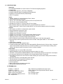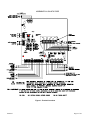
1
POWERPATH
PS-24-8MC
POWER BOOSTER
POWER SUPPLY
Installation Instructions
273 Branchport Avenue, Long Branch, NJ 07740-6899 Ph: (800) 631-2148 Fax: (732) 222-8707
Web Site: www.cooperwheelock.com e-mail: [email protected]
A84661-001A
Copyright 2007 Cooper Wheelock, Inc. All rights reserved
Thank you for using our products.
Use this product according to this instruction manual.
Please keep this instruction manual for future reference.
TABLE OF CONTENTS
1.0
1.1
1.2
1.3
1.4
1.5
1.6
2.0
2.1
2.2
2.3
2.4
2.4.1
2.4.2
3.0
3.1
3.2
3.3
3.4
3.5
3.6
4.0
5.0
6.0
INTRODUCTION AND SPECIFICATIONS:
INTRODUCTION
SPECIFICATIONS
TERMINOLOGY
TERMINAL IDENTIFICATION
LED STATUS
BATTERY MAINTENANCE
INSTALLATION INSTRUCTIONS:
UNPACKING
MOUNTING
WIRING
TROUBLE RELAY STATUS CONNECTIONS
AC LOSS TROUBLE TERMINALS
COMMON TROUBLE TERMINALS
OPERATION:
MODES OF OPERATION
DIP SWITCH SETTINGS
CLASS “B” OPERATION
CLASS “A” OPERATION WITHOUT OPTIONAL PS-4CA MODULE
CLASS “A” OPERATION WITH OPTIONAL PS-4CA MODULE
MASTER REMOTE OPERATION
TROUBLESHOOTING:
BATTERY CALCULATION SHEET:
WARRANTY STATEMENT:
COOPER WHEELOCK INC. COMPATIBLE APPLIANCES:
3
3
4
4
5
7
7
7
7
7
9
10
10
10
12
12
12
13
16
20
24
26
27
28
Appendix A
LIST OF FIGURES
Figure 1:
Figure 2:
Figure 3:
Figure 4:
Terminal Locations
Mounting Dimensions
POWERPATH PS-24-8MC
Output DIP Switch(s)
6
8
11
12
LIST OF TABLES
Table 1:
Table 2:
Table 3:
Table 4:
P84662J
Terminal Identification
LED Status Description
DIP Switch Selection
Troubleshooting
5
7
10
26
Page 2 of 28
NOTE: All CAUTIONS and WARNINGS are identified by the symbol
letters.
. All WARNINGS are printed in bold capital
WARNING: READ THIS INSTRUCTION MANUAL CAREFULLY. FAILURE TO COMPLY WITH ANY OF THE
FOLLOWING INSTRUCTIONS, CAUTIONS, AND WARNINGS COULD RESULT IN IMPROPER APPLICATION
AND/OR OPERATION OF THESE PRODUCTS IN AN EMERGENCY SITUATION, WHICH COULD RESULT IN
PROPERTY DAMAGE AND SERIOUS INJURY OR DEATH TO YOU AND/OR OTHERS.
1.0 INTRODUCTION AND SPECIFICATIONS:
1.1 INTRODUCTION
The PS-24-8MC POWERPATH is an 8 Amp, 24VDC, filtered and regulated, supervised remote power
supply/charger used for supervision and expanded power driving capability for Fire Alarm Notification Appliance
Circuits. The PS-24-8MC may be connected to any 12V or 24V (FWR or DC) Fire Alarm Control Panel (FACP)
by using a Notification Appliance Circuit (NAC) or a “Dry Contact”. Primary applications include NAC expansion
(supports ADA requirements) and auxiliary power to support system accessories. This unit provides filtered and
regulated 24VDC, 8 Amp up to four (4) Class "B", two (2) Class “A”, or two (2) Class “B” and one (1) Class “A”
Notification Appliance Circuits. With the optional plug-in PS-4CA module 101648 the unit supports (4) Class “A”
Notification Appliance Circuits. Additionally, an auxiliary power output of 3.5 Amps (disconnected upon AC
power loss or an alarm condition) or 200 mAmps (constant) is provided, which can be manually reset. The PS24-8MC also contains a battery charger capable of charging up to 20 Amp/Hour (AH) of battery backup.
Batteries larger than 12 AH will not fit inside cabinet, use of an external battery cabinet is necessary.
Two FACP NAC circuits or two “Dry” contact initiating circuits can be connected to the POWERPATH inputs.
These inputs can then be directed to control supervision and power delivery to any combination of the four (4)
outputs.
Each output is rated at 3.0 Amps (Class "B") or (Class "A") and can be programmed to generate a
steady or Code 3 Temporal Horn sound and a strobe output under alarm condition. Total load for the
PS-24-8MC NAC circuits shall not exceed 8.0 Amps.
The PS-24-8MC under non-alarmed condition provides independent loop supervision for Class “A” and Class “B”
FACP NAC circuits. In the event of a loop trouble, the FACP will be notified via the POWERPATH steered input
(IN1 or IN2). In addition there are two sets of trouble reporting terminals, one used for AC power loss reporting
and the other for all troubles. The AC power loss reporting, on the common trouble terminals, can be delayed
for either 30 seconds or 170 minutes. The AC power loss terminals will always report the trouble, 30 seconds
after loss of AC power.
Wheelock horns/strobes, strobes and horns with synchronizing capability can be utilized with the PS-24-8MC.
Audibles can be silenced with only two wires. Additionally, the POWERPATH can provide a temporal coded
signal for appliances that can utilize it.
P84662J
Page 3 of 28
1.2 SPECIFICATIONS
Approvals:
• UL Listed 864 Standard for Control Units for Fire Protective Signaling Systems
• Pending: FM
• Pending: MEA approved – NYC Dept. of Buildings
• Pending: California State Fire Marshall (CSFM) approved
• Pending: Fire Protection Bureau (FPB) Chicago
• NFPA 72 compliant
Inputs:
• 120VAC, 50/60Hz, 5.0 Amps Operating Power in Alarm
• 24VDC Battery Backup Connection
• Two (2), 12V or 24V NAC Initiating Circuits (8-33V at 7mA) FWR or DC
• Two (2) “Dry” Contact initiating Circuits
• Accepts two (2) Class “A” or two (2) Class “B” circuit inputs
• Built in battery charger for sealed lead acid or gel type batteries up to a 20 AH.
Batteries larger than 12 AH will not fit inside cabinet, use of an external battery cabinet is necessary.
Outputs:
• NAC outputs are 24VDC, 3.0 Amps each, power limited
• 8 Amps total alarm current for the unit
• Capable of four (4), Class "B" circuits
• Capable of two (2) Class “A” circuits
• Capable of four (4) Class “A” circuits (with optional PS-4CA module)
• Capable of one (1) Class “A” circuit and two (2) Class “B” circuits
• Temporal (Code 3) or constant voltage output generation
• Built-in Wheelock synchronization mode that can be fed to any or all of the output circuits
• Input and output can be synchronized with “IN>OUT SYNC” mode (SM, DSM or 2nd PS-24-8MC is
required)
• Audible silence capability
• Filtered and electronically regulated output
• 3.5 Amp auxiliary power limited output with reset capability. (Removed upon AC loss or alarm. Automatic
reset 30 seconds after AC power returns or the alarm condition is over) or 200 mAmps auxiliary power
limited output which remains on during AC loss or an alarm condition.
Supervision:
• Compatible with 12V or 24V (FWR or DC) FACP
• Signaling appliance loops are supervised and steered to either IN1 or IN2
• 2.2K Ohm, 1 Watt (Wheelock Model #MPEOL) End of Line Resistor (EOLR) for supervision of all outputs
• AC loss trouble reported over a separate set of contacts (delay of either 30 seconds)
• All troubles are reported over the common trouble contacts (AC loss can have a delay of 30 seconds or
170 minutes)
• Automatic switchover to standby battery when AC fails
• Thermal and short circuit protection with auto reset
• Input and output status LED indicators
• AC fail supervision
• Battery presence and low battery supervision
• Ground Fault Detection (60K ohms)
1.3 TERMINOLOGY
CLASS “A” = STYLE Z
CLASS “B” = STYLE Y
FACP = Fire Alarm Control Panel
EOLR = End of Line Resistor
NAC = Notification Appliance Circuit
AH = Ampere/Hour
P84662J
SM = Wheelock Sync Module with single output.
DSM = Wheelock Dual Sync Module with two outputs.
C = Common
NC = Normally Closed
NO = Normally Open
Page 4 of 28
1.4 TERMINAL IDENTIFICATION
Table 1: Terminal Identification
Terminal Block
Identification
Numbers (Figure 1)
TB1-1-3
TB5-1, 2
TB7-1, 2
Terminal
Identification
Function/Description
N,G,L
+ BAT IN1+,IN1-
TB7-3, 4
RET1+, RET1-
TB8-1, 2
TB8-5, 4
TB7-5, 6
IN2+, IN2RET2+, RET2C “DRY1” NC
TB8-5, 6
C “DRY2” NC
TB6-1, 2
TB6-3, 4
TB6-5, 6
TB6-7, 8
+OUT1+OUT2+OUT3+OUT4-
TB4-1-3
“NO” “C” “NC”
(COMMON
TROUBLE
OUTPUT)
“NO” “C” “NC”
(AC LOSS
TROUBLE
OUTPUT)
+ AUX -
AC power input terminals 120VAC, 50-60Hz.
24VDC Battery connection.
These terminals connect to the input voltage source (i.e. 12VDC or
24VDC FACP). The FACP will supply a voltage from 8-33V (FWR or DC)
at 7mA. During the alarm condition these inputs will cause the designated
outputs to drive the notification appliances (designated outputs are set by
output DIP switch banks). During Stand-by the PS-24-8MC can report
troubles from the designated loop by opening the FACP’s initiation loop.
During an alarm condition the PS-24-8MC closes the loop to ensure that
the alarm condition will be passed through to the next device on the loop.
EOLR is connected on these terminals corresponding to IN1+ and IN1-,
or the loop may be continued to other power supplies or appliances
before terminating.
Same as IN1+, IN1- for corresponding terminals.
Same as RET1+, RET1- for corresponding terminals.
Dry contacts are used to actuate the designated outputs. Contacts are
normally closed and actuate the power supply on contact Open.
Designated outputs correspond to IN1+,IN1-. NOTE: Wiring must remain
in the same room in conduit. NOTE: FACP NAC circuit cannot energize
the power supply by these contacts. NOTE: When these terminals are
not in use, a jumper must be connected across them.
Operates the same as IN2+,IN2- for corresponding terminals. When
these terminals are not in use, a jumper must be connected across them.
NOTE: Wiring must remain in the same room in conduit.
Indicating appliances are connected to these outputs (See Examples in
Operation Section). Each output can supply a maximum load of 3.0
Amps Class "B" or Class "A" and can be individually programmed for
Normal Mode, Temporal Mode, IN>OUT SYNC Mode, or WHEELOCK
SYNC Mode. The outputs can be configured as four Class "B" circuits,
two Class "A" circuits, or two Class "B" and one Class "A" circuits. With
the optional PS-4CA module 101648 the unit can provide four Class “A”
circuits. Outputs are controlled by a designated input (INPUT 1 or 2) as
selected by the DIP switch for that output. NOTE: When the panel has
been set to synchronization mode, IN1 is used for strobe activation and
IN2 is used for audible silence. Individual output control is disabled.
Typically used to trigger remote alerts or other reporting appliances.
Form C contacts rated 28VDC at 1 Amp. Resistive
TB2-1-3
TB9-1, 2
P84662J
Used for local reporting of AC power loss to trigger remote alerts or other
reporting appliances. Form C contacts rated 28VDC at 1 Amp. Resistive
AUX output is rated 20.1 to 28VDC, special applications. (See Appendix
A for suitable devices). In MP mode: AUX output is capable of 3.5Amps,
and can be reset by a momentary switch on the board. The 3.5 Amps of
power is disconnected when AC power is lost or the unit is in alarm. The
3.5 Amps of power is reconnected 30 seconds after AC power returns or
the alarm condition is over. In CP mode: The AUX output is capable of
200mAmps with 12AH battery or 70mAmps with 7AH battery. In CP
mode, power is available during AC power loss (batteries connected) and
during an alarm condition.
Page 5 of 28
ASSEMBLED IN USA WITH PRIDE
TB2
TB4
TB7
Figure 1: Terminal Locations
P84662J
Page 6 of 28
1.5 LED STATUS
Table 2 lists status of the LED indicators. The ALARM condition occurs when the input causes the output
circuits to energize. The TROUBLE LED’s for OUT1, OUT2, OUT3, OUT4 and, GND FAULT latch ON when
the trouble occurs. They are turned OFF when an alarm condition occurs or the PS-24-8MC system reset
switch (SW5) is pressed. The GND FAULT, BATT and, MICRO FAULT LED’s turn ON when the trouble
occurs. The trouble relays (AC loss and Common trouble) follow the trouble condition and are non-latching.
NOTE: An alarm condition overrides a trouble condition.
Table 2: LED Status Description
LED
OUT1
OUT2
OUT3
OUT4
INP1
INP2
GND FAULT
AC
BATT
MICRO FAULT
POWER SUPPLY DC
•
OFF
STANDBY
STANDBY
STANDBY
STANDBY
STANDBY
STANDBY
-------No AC
--------------TROUBLE
ON
----------------------------ALARM
ALARM
TROUBLE
AC Present
TROUBLE
TROUBLE
DC PRESENT
ON
TROUBLE
TROUBLE
TROUBLE
TROUBLE
TROUBLE*
TROUBLE*
------------------------------------
NOTE: If INP1 or INP2 LED and OUT1-OUT4 TROUBLE LED are on, TROUBLE exists currently.
1.6 BATTERY MAINTENANCE
Replace batteries every four (4) years or as needed if battery will no longer accept full charge, two 12V
batteries are required. Battery capacity must be in accordance with the proper battery calculation for the
application using BATTERY CALCULATION SHEET provided on page 27.
NOTE: Battery compartment measures 4.50" High 12.50" Wide 5.00" Deep.
2.0 INSTALLATION INSTRUCTIONS:
NOTE: The PS-24-8MC POWERPATH shall be installed in accordance with the National Fire Protection
Association (NFPA), National Electrical Code (NEC) and all applicable state and local regulations.
2.1 UNPACKING
The POWERPATH was carefully checked before leaving the factory. Inspect shipping container and unit
carefully for indications of improper handling. If damage is detected, make an immediate claim to the carrier.
Remove the POWERPATH from the shipping container and check that the door lock keys, door lock, and
battery connection wires are inside. Make sure the printed circuit board is securely mounted to the rear of
the enclosure.
2.2 MOUNTING
WARNING: TO REDUCE THE RISK OF FIRE OR ELECTRIC SHOCK, DO NOT EXPOSE THIS UNIT
TO RAIN OR MOISTURE.
CAUTION: This product is not intended for use in hazardous locations as defined by the National
Electrical Code (NEC) and by the National Fire Protection Association (NFPA).
The POWERPATH unit is to be mounted in an indoor, dry location using the mounting dimensions in Figure
2.
Mount the panel in a location that does not exceed a temperature range of 0 C to 49 C (32 F to 120 F)
and a humidity equal to 10% to 93% at 30 C (86 F) non-condensing.
When mounting on interior walls, use proper screw anchors in plaster. When mounting to concrete,
especially when moisture is expected, first attach a piece of ¾ inch plywood to the concrete surface. Attach
the POWERPATH to the plywood.
P84662J
Page 7 of 28
5.00"
7.452"
Figure 2: Mounting Dimensions
DIMENSIONS (H x W x D) - 16.70” x 12.83” x 5.00”
NOTE: All dimensions shown are in inches
CAUTION: Use care when punching out knock-outs to avoid damage to internal components.
P84662J
Page 8 of 28
2.3 WIRING
WARNING: MAKE SURE THAT THE TOTAL RMS CURRENT REQUIRED BY ALL APPLIANCES
THAT ARE CONNECTED TO THE PS-24-8MC’s NOTIFICATION APPLIANCE CIRCUITS DOES NOT
EXCEED THE PS-24-8MC’s RATED CAPACITY (8 AMPS MAXIMUM) OR THE CURRENT RATINGS OF
ANY INDIVIDUAL NOTIFICATION APPLIANCE CIRCUIT (3 AMPS MAXIMUM). OVERLOADING THE
PS-24-8MC COULD RESULT IN LOSS OF POWER AND FAILURE TO ALERT OCCUPANTS DURING
AN EMERGENCY, WHICH COULD RESULT IN PROPERTY DAMAGE AND SERIOUS INJURY OR
DEATH TO YOU AND/OR OTHERS.
Review the Operation Section (3.0) in order to select the proper hook-up and use of the POWERPATH. Set
switches and wire the POWERPATH as follows: Terminal and switch locations are shown in Figure 1.
A. Set output DIP Switch(s) to follow corresponding input (IN1, IN2) and desired output mode. See Table
3 DIP Switch Selection and DIP Switch Settings Section (3.2).
B. Set DIP Switch SW7 position 1 & 2 to select Class “A” or Class “B” operation (Off for Class "B", On for
Class "A").
Note: When the PS-24-8MC is used with the optional PS-4CA module, the main board Class switches
must be set to Class “B”.
C. Select the mode of operation for the Auxiliary output (JP2) to either managed power (MP) or constant
power (CP). In the MP mode of operation the Auxiliary output is disconnected upon AC loss or an
alarm condition. The power is reconnected 30 seconds after AC power returns or the alarm condition
is over. The power is not disconnected when in the CP mode of operation.
D. Select the delay, before AC loss trouble will be reported to the common trouble terminals (JP1) to
either SHORT DLY or LONG DLY. LONG DLY is 170 minutes and SHORT DLY is 30 seconds.
E. If using the optional PS-4CA module install it now.
F. Dress the battery wires down to the back of the enclosure, observing ¼” separation of power limited
wire V.S. non-power limited wiring. See Figure 3.
G. Connect notification appliances to desired outputs OUT1 – OUT4 See Operation Section (3.0).
• The POWERPATH has in-out wiring terminals that accept two #18 to #12 American Wire Gauge
(AWG) wires at each screw terminal. Strip leads 3/8 inches and connect to screw terminals.
Maximum line impedance is 39 ohms or 3.4 volt drop, whichever is more.
• Separate all in-out wire runs on supervised circuits to insure integrity of circuit supervision. The
polarity shown in the wiring diagrams and on the circuit boards is for operation of the appliances.
The polarity is reversed by the FACP during supervision.
• Total load for the PS-24-8MC NAC circuits shall not exceed 8.0 Amps.
• Total load of any NAC output circuit shall not exceed 3.0 Amps.
• In Class “B” mode of operation terminate unused outputs with a 2.2K Ohm EOLR.
• In Class “A” mode of operation connect unused outputs to there respective returns.
• When using the optional PS-4CA module connect unused outputs to there respective returns.
H. Connect the NAC circuit(s) from the FACP to the desired input(s), IN1 and IN2. Connect EOLR to
RET1 and RET2. The value is determined by FACP manufacture.
I. Connect desired auxiliary equipment to the auxiliary output terminals +AUX-.
J. Connect AC loss trouble relay as desired.
K. Connect the common trouble relay as desired.
L. Connect AC source. The AC source shall be connected to a dedicated, non-switch power source.
The AC must first be wired into the buildings main electrical power. The conduit entry can be either
from the top or left hand side using the knock-outs. See Figure 3. Connect Earth Ground First.
M. Connect backup batteries. Observe correct polarity, use two of the same connected in series. Use
either a 7AH or a 12AH battery depending on circuit loading, BATTERY CALCULATION SHEET is
provided on Sheet 27.
N. Install battery cover between both battery wires and Power Limited Wiring. See Figure 3.
O. Press Auxiliary Power Reset, SW6 to ensure that Auxiliary Power is present.
P. Close door and lock.
P84662J
Page 9 of 28
Table 3: DIP Switch Selection
Function
INPUT
SELECT
TEMPORAL
IN>OUT SYNC
WHEELOCK
SYNC MODE
Switch Position
ON
Description
Selected output to be controlled by Input 1 (IN1+, IN1-) (DRY1)
Note
------
OFF
ON
Selected output to be controlled by Input 2 (IN2+, IN2-) (DRY2)
Generates Code 3 temporal signal on this output.
-----1
Allows a sync signal on the input to be used by the output.
Generates Wheelock sync signal for synchronizing Wheelock horns
and strobes.
-----2
ON
WHEELOCK SYNC “ON”
IN>OUT SYNC “ON”
NOTE 1: Use only with appliances that can operate using a coded horn appliance. (Example: Wheelock
Series CH, and Series MT)
NOTE 2: Use only with Wheelock Series AS/AH, Series NS/NS4/NH, Series RSS and products with SL/SLM
strobes.
2.4 TROUBLE RELAY STATUS CONNECTIONS
2.4.1
AC LOSS TROUBLE TERMINALS
The AC LOSS TROUBLE TERMINALS are located on the left side of the PC board and used for
transmission of local trouble annunciation. The three terminals are labeled “NO”, “C” and “NC”. When
the PS-24-8MC is operating normally the “NC” “C” terminals are shorted, and the “C” “NO” terminals
are open. This set of terminals reports AC LOSS after a 30 second delay. (Immediate/Short Delay
Only).
2.4.2
COMMON TROUBLE TERMINALS
The COMMON TROUBLE TERMINALS are located on the left side of the PC Board. The three
terminals are labeled “NO”, “C” and “NC”. When the PS-24-8MC is operating normally the “NC” “C”
terminals are shorted, and the “C” “NO” terminals are open. There are five trouble conditions that will
cause these terminals to change state.
•
•
Supervision trouble on any output
(+OUT1-, +OUT2-, +OUT3-, +OUT4-)
Micro Processor Fault
•
•
Battery Fail
•
GND Fault
AC Loss
When the trouble is cleared the COMMON TROUBLE TERMINALS return to the operating normally
condition.
AC LOSS reporting on the COMMON TROUBLE TERMINALS can be selected for 30 seconds (Immediate/Short
Delay) or 170 minutes (Long Delay). (170 minutes is used for delay of Off-premise trouble
annunciation)
P84662J
Page 10 of 28
TB2
TB4
TB7
Figure 3: POWERPATH PS-24-8MC
P84662J
Page 11 of 28
3.0 OPERATION:
3.1 MODES OF OPERATION
The PS-24-8MC POWERPATH can provide 24VDC output when initiated by a 8V to 33V (FWR or DC)
appliance (IN1 or IN2) or an open contact (DRY1 or DRY2). The output will remain on until the
deactivation of the input returns it to standby mode.
The outputs can be configured as four Class “B” circuits, two Class “A” circuits, or two Class “B” and one
Class “A” circuits. With the optional plug in PS-4CA module 101648 the unit supports four Class “A”
Notification Appliance Circuits.
Each Class "A" circuit or Class "B" circuit is 3.0 Amps. Total load for the PS-24-8MC NAC circuits shall not
exceed 8.0 Amps.
There are four output modes which can be used with either Class “A” or Class “B” circuits.
NORMAL MODE
Used for a constant 24VDC output.
TEMPORAL MODE
Provides a temporal output for appliances that can utilize a coded
signal. (i.e. single stroke bells and chimes and some horns) (NOTE:
Do not use with Wheelock AS, NS, RSS appliances.)
IN>OUT SYNC MODE
Allows ONLY a coded signal or Wheelock synchronization signal input
to be utilized by the POWERPATH. This signal may come from a
FACP, another PS-24-8MC or a Wheelock Synchronization Module
(SM-12/24 or DSM-12/24). Audibles can also be silenced.
WHEELOCK SYNC MODE
Activates the built-in Wheelock Synchronization Mode for use with
patented Wheelock synchronized horns and strobes. Audibles can
also be silenced.
3.2 DIP SWITCH SETTINGS
The following is the DIP Switch settings for the Outputs.
When switches are changed, press SYS RESET and wait 10 seconds before activating.
Figure 4: Output DIP Switch(s)
1
2
3
4
OUT1-4
IN>OUT SYNC
WHEELOCK SYNC
TEMPORAL
INPUT SELECT
ON
MODE
NORMAL MODE
TEMPORAL
IN>OUT SYNC
WHEELOCK SYNC
P84662J
DIP SWITCH SETTING
INPUT SELECT (1)
“ON” for “IN1” or “DRY1”
“OFF” for “IN2” or “DRY2”
TEMPORAL (2)
“OFF”
WHEELOCK SYNC (3)
“OFF”
IN>OUT SYNC (4)
“OFF”
INPUT SELECT (1)
“ON” for “IN1” or “DRY1”
“OFF” for “IN2” or “DRY2”
TEMPORAL (2)
“ON”
WHEELOCK SYNC (3)
“OFF”
IN>OUT SYNC (4)
“OFF”
INPUT SELECT (1)
“ON” for “IN1” or “DRY1”
“OFF” for “IN2” or “DRY2”
TEMPORAL (2)
“OFF”
WHEELOCK SYNC (3)
“OFF”
IN>OUT SYNC (4)
“ON”
INPUT SELECT (1)
“ON” for “IN1” or “DRY1”
“OFF” for “IN2” or “DRY2”
TEMPORAL (2)
“OFF”
WHEELOCK SYNC (3)
“ON”
IN>OUT SYNC (4)
“ON”
Page 12 of 28
3.3 CLASS “B” OPERATION
Class “B” outputs can be controlled from either IN1 or IN2. Switch SW7 position 1 & 2 on the PC board are
in the “OFF” position.
The following are examples of Class “B” connections. A FACP is used as a representative input.
•
IN1 and/or IN2 can be used for connection to the FACP. The INPUT SELECT Switch (1) selects which
input is to be used to activate the output.
•
Board switch SW7 position 1 & 2 control Class “A” or Class “B” configuration. SW7 position 1 controls
Outputs 1 and 3. SW7 position 2 controls Outputs 2 and 4.
•
The PS-24-8MC requires a 2.2K Ohm End of Line Resistor (EOLR) on each output for proper
supervision.
3
4
Example 1: NORMAL MODE (CLASS B)
F
A
C
P
1
2
+
IN1
ON
TO NEXT APPLIANCE
OR EOLR
+
+
TO NEXT APPLIANCE
OR EOLR
(2.2K OHMS)
+
TO NEXT APPLIANCE
OR EOLR
(2.2K OHMS)
OUT1-4
IN>OUT SYNC
WHEELOCK SYNC OUT1
TEMPORAL
INPUT SELECT
-
OUT2
RET1
-
-
POWERPATH
+
TO NEXT APPLIANCE
OR EOLR
(2.2K OHMS)
OUT3
-
SW7
ON
+
2
1
3
TO NEXT APPLIANCE
OR EOLR
(2.2K OHMS)
OUT4
4
-
LEGEND
AUDIBLE
STROBE
Example 2: TEMPORAL MODE (CLASS B)
+
4
3
+
1
ON
TO NEXT APPLIANCE
+
3
OR EOLR
4
RET1
-
2
1
F
A
C
P
2
IN1
-
ON
TO NEXT APPLIANCE
OR EOLR
(2.2K OHMS)
OUT1
IN>OUT SYNC OUT1
WHEELOCK SYNC
TEMPORAL
INPUT SELECT
OUT2-4
IN>OUT SYNC
+
WHEELOCK SYNC
TEMPORAL
INPUT SELECT OUT2
TO NEXT APPLIANCE
OR EOLR
(2.2K OHMS)
-
POWERPATH
OUT3
SW7
ON
1
2
3
4
OUT4
+
-
+
-
EOLR
2.2K OHMS
EOLR
2.2K OHMS
CAUTION: Strobes require constant voltage and will not operate properly in the TEMPORAL MODE. A second
output set in the NORMAL MODE will provide the constant voltage.
CAUTION: Only use audible appliances that can use a coded signal. Do not use with Wheelock Series AS/AH,
NS/NH or HS4/HS appliances.
P84662J
Page 13 of 28
Example 3:
IN>OUT SYNC MODE from CODED INPUT SOURCE (CLASS B)
CODED
+
+
IN1
4
-
3
+
1
F
A
C
P
OR EOLR
2
TO NEXT APPLIANCE
TO NEXT APPLIANCE
OR EOLR
(2.2K OHMS)
OUT1-4
ON
- RET1
OUT1
IN>OUT SYNC
WHEELOCK SYNC
TEMPORAL
INPUT SELECT
+
+
IN2
-
+
-
TO NEXT APPLIANCE
OR EOLR
(2.2K OHMS)
OUT2
-
POWERPATH
RET2
OUT3
+
-
EOLR
2.2K OHMS
SW7
ON
1
2
3
OUT4
4
+
-
EOLR
2.2K OHMS
Minimum pulse duration for coded signals must be greater than 0.25 seconds.
CAUTION: Only use audible appliances that can use a coded signal. Do not use with Wheelock Series AS/AH,
NS/NH or HS4/HS appliances.
Example 4:
IN>OUT SYNC MODE with External Sync Module without Audible Silence
(CLASS B)
SM/DSM
3
2
+ IN1
1
F
A
C
P
4
+ OUT1
ON
MINUS 1
+ AUDIBLE
- AUDIBLE
TO NEXT APPLIANCE
OR EOLR
TO NEXT
APPLIANCE
OR EOLR
(2.2K OHMS)
+
+
IN1
-
OUT1-4
OUT1
IN>OUT SYNC
WHEELOCK SYNC
TEMPORAL
INPUT SELECT
OUT2
+
RET1
+
-
EOLR
2.2K OHMS
-
POWERPATH
OUT3
+
-
EOLR
2.2K OHMS
SW7
ON
OUT4
1
2
3
4
+
-
EOLR
2.2K OHMS
NOTE: When using the Wheelock external Sync Module (SM or DSM), synchronization will only occur with
Wheelock sync appliances.
P84662J
Page 14 of 28
Example 5:
IN>OUT SYNC MODE with External Sync Module with Audible Silence
(CLASS B)
SM/DSM
+
EOLR
1
MINUS 1
TO NEXT
APPLIANCE
OR EOLR
2
F
A
C
P
+ IN1
3
+ OUT1
4
+
IN1
ON
+
RET1
-
+ AUDIBLE
OUT2
POWERPATH
- AUDIBLE
TO NEXT APPLIANCE
OR EOLR
(2.2K OHMS)
OUT1-4
IN>OUT SYNC
WHEELOCK SYNC OUT1
TEMPORAL
INPUT SELECT
OUT3
+
-
+
-
EOLR
2.2K OHMS
EOLR
2.2K OHMS
SW7
ON
OUT4
1
2
3
4
+
-
EOLR
2.2K OHMS
NOTE: When using the Wheelock external Sync Module (SM or DSM), synchronization will only occur with
Wheelock sync appliances.
Example 6:
WHEELOCK SYNC MODE without Audible Silence (CLASS B)
4
+ IN1
-
3
2
1
F
A
C
P
ON
+
OUT1-4
RET1
+
OUT2
+
-
EOLR
2.2K OHMS
POWERPATH
+
- IN2
+
-
OUT3
+
-
EOLR
2.2K OHMS
RET2 TO NEXT APPLIANCE
OR EOLR
SW7
ON
OUT4
1
•
•
•
TO NEXT APPLIANCE
OR EOLR
(2.2K OHMS)
IN>OUT SYNC
OUT1
WHEELOCK SYNC
TEMPORAL
INPUT SELECT
2
3
+
-
EOLR
2.2K OHMS
4
This mode will only synchronize Wheelock horns, horn strobes, and strobes with the synchronization capability.
If only strobes are connected to the POWERPATH outputs, the initiating input to IN2 is not required.
When synchronized horns are used on the two wire output of the POWERPATH, IN2 must be connected as
shown or the horns will not operate.
P84662J
Page 15 of 28
Example 7: WHEELOCK SYNC MODE with Audible Silence (CLASS B)
+
IN1
2
1
ON
TO NEXT APPLIANCE
OR EOLR
+
RET1
-
AUDIBLE
SILENCE
TO NEXT APPLIANCE
OR EOLR
OUT2
POWERPATH
+
IN2
+
-
OUT3
+
-
+
-
EOLR
2.2K OHMS
EOLR
2.2K OHMS
RET2
SW7
ON
OUT4
1
•
TO NEXT APPLIANCE
OR EOLR
(2.2K OHMS)
IN>OUT SYNC
OUT1
WHEELOCK SYNC
TEMPORAL
INPUT SELECT
3
F
A
C
P
+
OUT1-4
4
-
2
3
4
+
-
EOLR
2.2K OHMS
This mode will only synchronize Wheelock horns, horn strobes, and strobes with the synchronization capability.
3.4 CLASS “A” OPERATION WITHOUT OPTIONAL PS-4CA MODULE
Class “A” circuit 1 uses “OUT1” and “OUT3”. Class “A” circuit 2 uses “OUT2” and “OUT4”. When
operating in Class “A” the two circuits must have the same switch settings for the operational mode
selected. Switch SW7 position 1 & 2 on the PC board are in the “ON” position.
•
•
•
IN1 and/or IN2 can be used for connection to the FACP. The INPUT SELECT Switch (1) selects which
input is to be used to activate the output.
Board switch SW7 position 1 & 2 control Class “A” or Class “B” configuration. SW7 position 1 controls
Outputs 1 and 3. Switch SW7 position 2 controls Outputs 2 and 4.
DIP Switch settings for each circuit in the Class “A” output must be set identically.
Example 8: NORMAL MODE (CLASS A)
OUT1-4
4
+
IN1
3
-
2
1
F
A
C
P
ON
TO NEXT APPLIANCE
OR EOLR
OR RETURN
TO FACP
(CLASS "A")
IN>OUT SYNC
WHEELOCK SYNC
TEMPORAL
INPUT SELECT
OUT2 +
-
+
RET1
-
POWERPATH
OUT3 +
SW7
ON
1
P84662J
+
OUT1 -
2
3
4
OUT4 +
Page 16 of 28
Example 9: TEMPORAL MODE (CLASS A)
OUT1
OUT2
-
ON
OUT4
3
3
OUT2 +
-
4
4
2
2
1
1
IN>OUT SYNC
WHEELOCK SYNC
TEMPORAL
INPUT SELECT
ON
1
RET1
2
ON
+
3
1
F
A
C
P
2
-
TO NEXT APPLIANCE
OR EOLR
OR RETURN
TO FACP
(CLASS "A")
+
OUT1 -
4
3
IN1
OUT3
IN>OUT SYNC
WHEELOCK SYNC
TEMPORAL
INPUT SELECT
4
+
ON
POWERPATH
OUT3 +
SW7
ON
OUT4 +
1
2
3
4
CAUTION: Strobes require constant voltage and will not operate properly in the TEMPORAL MODE. A second
Class “A” output set in the NORMAL MODE will provide the constant voltage for the strobe circuit. Only use
sounding appliances that can use a coded signal. Do not use Wheelock AS/AH or NS/NS4/NH appliances with
TEMPORAL MODE.
Example 10: IN>OUT SYNC MODE from CODED INPUT SOURCE (CLASS A)
CODED
OUT1
ON
RET1
-
OUT2
2
2
1
1
+
OUT2+
-
3
3
IN>OUT SYNC
WHEELOCK SYNC
TEMPORAL
INPUT SELECT
+
-
OUT4
4
4
ON
IN2
1
ON
OUT1 -
2
1
+
+
3
-
2
F
A
C
P
TO NEXT APPLIANCE
OR EOLR
OR RETURN
TO FACP
(CLASS "A")
3
IN1
OUT3
IN>OUT SYNC
WHEELOCK SYNC
TEMPORAL
INPUT SELECT
4
4
+
ON
-
OUT3 +
POWERPATH
RET2
-
SW9
-
ON
OUT4 +
1
2
3
4
Minimum pulse duration for coded signals must be greater than 0.25 seconds.
P84662J
Page 17 of 28
Example 11:
IN>OUT SYNC MODE with External Sync Module without Audible Silence
(CLASS A)
SM/DSM
+
IN1
-
3
2
F
A
C
P
OUT1-4
4
+ OUT1
1
+ IN1
+
OUT1 -
ON
MINUS 1
+ AUDIBLE
IN>OUT SYNC
WHEELOCK SYNC
TEMPORAL
INPUT SELECT
TO NEXT APPLIANCE
OR EOLR
- AUDIBLE
OUT2 +
+
RET1
-
POWERPATH
-
OUT3 +
SW7
-
ON
OUT4 +
2
1
4
3
NOTE: When using the Wheelock external Sync Module (SM or DSM), synchronization will only occur with
Wheelock sync appliances.
Example 12: IN>OUT SYNC MODE with External Sync Module with Audible Silence
(CLASS A)
SM/DSM
+
IN1
-
3
+ IN1
2
1
F
A
C
P
OUT1-4
4
+ OUT1
EOLR
+ AUDIBLE
- AUDIBLE
+
OUT1 -
ON
MINUS 1
AUDIBLE
SILENCE
IN>OUT SYNC
WHEELOCK SYNC
TEMPORAL
INPUT SELECT
TO NEXT APPLIANCE
OR EOLR
OUT2 +
-
+
RET1
-
POWERPATH
-
OUT3 +
SW7
ON
OUT4 1
2
3
4
+
NOTE: When using the Wheelock external Sync Module (SM or DSM), synchronization will only occur with
Wheelock sync appliances.
P84662J
Page 18 of 28
Example 13: WHEELOCK SYNC MODE without Audible Silence (CLASS A)
OUT1-4
4
3
2
1
F
A
C
P
+
-IN1
IN>OUT SYNC
WHEELOCK SYNC
TEMPORAL
INPUT SELECT
ON
+RET1
OUT2 +
-
POWERPATH
+
- IN2
TO NEXT APPLIANCE
OR EOLR
OR RETURN
TO FACP
(CLASS "A")
-
OUT3 +
-
RET2
+
SW7
ON
OUT4 -
+
2
1
•
•
•
+
OUT1 -
4
3
This mode will only synchronize Wheelock horns, horn strobes, and strobes with the synchronization capability.
If only strobes are connected to the POWERPATH outputs, the initiating input to IN2 is not required.
When synchronized horns are used on the two wire output of the POWERPATH, IN2 must be connected as
shown or the horns will not operate.
Example 14: WHEELOCK SYNC MODE with Audible Silence (CLASS A)
+
OUT1-4
-
IN>OUT SYNC
WHEELOCK SYNC
TEMPORAL
INPUT SELECT
4
IN1
3
2
1
F
A
C
P
ON
TO NEXT APPLIANCE
OR EOLR
OR RETURN
TO FACP
(CLASS "A")
AUDIBLE SILENCE
+
+
IN2
TO NEXT APPLIANCE
OR EOLR
OR RETURN
TO FACP
(CLASS "A")
OUT2 +
RET1
-
-
-
POWERPATH
OUT3 +
+
RET2
-
SW7
ON
OUT4 +
1
•
+
OUT1 -
2
3
4
This mode will only synchronize Wheelock horns, horn strobes, and strobes with the synchronization capability.
COMBINATION CLASS “A” AND CLASS “B” HOOKUP
The PS-24-8MC POWERPATH can be configured to have one Class “A” (3.0 Amps) and two Class “B” (3.0 Amps
each circuit) outputs at the same time, with a maximum 8 Amps total for the unit. This is done by Switch SW7
position 1 & 2. NOTE: When SW7 position 1 is ON, OUTPUTS 1 and 3 are the Class “A” circuit. When SW7
position 2 is ON, OUTPUTS 2 and 4 are the Class “A” circuit.
COMBINATION OF MODES
•
•
•
In Class “B” configuration, each output can be set to an independent mode as desired.
In Class “B”, IN1 or IN2 can be selected to activate any of the outputs desired.
In Class “A”, OUTPUT DIP Switches must be set identically for each Class “A” output.
P84662J
Page 19 of 28
3.5 CLASS “A” OPERATION WITH OPTIONAL PS-4CA MODULE
When using the PS-4CA Class “A” module switch SW7 position 1 & 2 on the board are in the “OFF”
position.
The following are examples of Class “A” connections with the PS-4CA module. A FACP is used as a
representative input.
•
IN1 and/or IN2 can be used for connection to the FACP. The INPUT SELECT Switch (1) selects which input is
to be used to activate the output.
Example 15: NORMAL MODE (CLASS A using the PS-4CA module)
+
RET1
IN1
+
RET1
+
-
RET2
OUT1-4
IN>OUT SYNC
WHEELOCK SYNC
TEMPORAL
INPUT SELECT
2
3
4
-
+
OUT1
1
F
A
C
P
TO NEXT APPLIANCE
OR EOLR
OR RETURN
TO FACP
(CLASS "A")
+
-
ON
-
+
-
RET3
-
ON
4
3
+
OUT3
RET4
2
+
OUT2
SW7
1
-
+
-
+
OUT4
PS-24-8MC
PS-4CA
-
LEGEND
AUDIBLE
STROBE
Example 16: TEMPORAL MODE (CLASS A using the PS-4CA module)
+
RET1
IN1
+
-
RET1
1
2
3
4
-
+
OUT1
ON
OUT1-4
IN>OUT SYNC
WHEELOCK SYNC
TEMPORAL
INPUT SELECT
RET2
OUT1-4
IN>OUT SYNC
TEMPORAL
INPUT SELECT
RET3
+
-
+
OUT2
-
2
3
4
OUT1
1
F
A
C
P
TO NEXT APPLIANCE
OR EOLR
OR RETURN
TO FACP
(CLASS "A")
+
-
ON
+
-
SW7
RET4
ON
1
2
3
+
-
+
OUT4
-
4
PS-24-8MC
+
OUT3
-
OUT2-4
PS-4CA
CAUTION: Strobes require constant voltage and will not operate properly in the TEMPORAL MODE. A second
output set in the NORMAL MODE will provide the constant voltage.
CAUTION: Only use audible appliances that can use a coded signal. Do not use with Wheelock Series AS/AH,
NS/NH or HS4/HS appliances.
P84662J
Page 20 of 28
Example 17: IN>OUT SYNC MODE from CODED INPUT SOURCE
(CLASS A using the PS-4CA module)
+
-
RET1
+
IN1
+
-
RET1
OUT 1-4
IN>OUT SYNC
WHEELOCK SYNC
TEMPORAL
INPUT SELECT
2
3
4
-
+
OUT1
1
F
A
C
P
TO NEXT APPLIANCE
OR EOLR
OR RETURN
TO FACP
(CLASS "A")
ON
+
-
RET2
+
OUT2
-
+
RET3
-
+
OUT3
-
SW7
ON
+
RET4
-
1
2
3
+
OUT4
4
PS-24-8MC
-
PS-4CA
Minimum pulse duration for coded signals must be greater than 0.25 seconds.
CAUTION: Only use audible appliances that can use a coded signal. Do not use with Wheelock Series AS/AH,
NS/NH or HS4/HS appliances.
Example 18: IN>OUT SYNC MODE with External Sync Module without Audible Silence
(CLASS A using the PS-4CA module)
SM/DSM
+
+
-
+
OUT1
+ IN1
MINUS 1
+
TO NEXT APPLIANCE
OR EOLR
-
-
RET1
RET2
+
-
4
3
- AUDIBLE
2
EOLR
+
OUT2
+ AUDIBLE
1
F
A
C
P
RET1
IN1
-
+ OUT1
ON
IN>OUT SYNC
WHEELOCK SYNC
TEMPORAL
INPUT SELECT
RET3
+
-
OUT1-4
+
OUT3
-
SW7
ON
RET4
1
2
3
+
-
PS-24-8MC
+
OUT4
4
PS-4CA
-
NOTE: When using the Wheelock external Sync Module (SM or DSM), synchronization will only occur with
Wheelock sync appliances.
P84662J
Page 21 of 28
Example 19: IN>OUT SYNC MODE with External Sync Module with Audible Silence
(CLASS A using the PS-4CA module)
SM/DSM
RET1
-
TO NEXT APPLIANCE
+
OR EOLR
RET2
RET1
MINUS 1
+
OUT1
IN1
+ IN1
-
4
OUT1-4
IN>OUT SYNC
WHEELOCK SYNC
TEMPORAL
INPUT SELECT
2
3
+ AUDIBLE
EOLR
+
-
-
+ OUT1
- AUDIBLE
1
F
A
C
P
+
ON
+
-
+
OUT2
-
RET3
+
-
+
OUT3
OUT2-4
-
SW7
ON
+
RET4
-
+
OUT4
1
2
3
4
PS-24-8MC
PS-4CA
-
NOTE: When using the Wheelock external Sync Module (SM or DSM), synchronization will only occur with
Wheelock sync appliances.
Example 20:
WHEELOCK SYNC MODE without Audible Silence
(CLASS A using the PS-4CA module)
+
RET1
IN1
+
OUT2
-
3
ON
OUT1-4
IN>OUT SYNC
WHEELOCK SYNC
TEMPORAL
INPUT SELECT
RET3
+
-
+
OUT3
-
SW7
+
RET4
-
ON
1
2
3
+
OUT4
4
PS-24-8MC
•
•
•
+
-
RET2
2
-
RET2
4
+
+
-
+ IN2
TO NEXT APPLIANCE
OR EOLR
OR RETURN
TO FACP
(CLASS "A")
+
-
OUT1
1
F
A
C
P
+
- RET1
PS-4CA
-
This mode will only synchronize Wheelock horns, horn strobes, and strobes with the synchronization capability.
If only strobes are connected to the POWERPATH outputs, the initiating input to IN2 is not required.
When synchronized horns are used on the two wire output of the POWERPATH, IN2 must be connected as
shown or the horns will not operate.
P84662J
Page 22 of 28
Example 21: WHEELOCK SYNC MODE with Audible Silence
(CLASS A using the PS-4CA module)
RET1
+
IN1
+
-
+
-
-
RET1
RET2
+
+
-
IN2
+
RET2
RET3
3
4
-
ON
OUT1-4
IN>OUT SYNC
WHEELOCK SYNC
TEMPORAL
INPUT SELECT
SW7
+
-
+
-
+
RET4
-
ON
2
3
4
PS-24-8MC
-
OUT3
+
OUT4
1
•
+
OUT2
2
TO NEXT APPLIANCE
OR EOLR
OR RETURN
TO FACP
(CLASS "A")
+
OUT1
1
F
A
C
P
TO NEXT APPLIANCE
OR EOLR
OR RETURN
TO FACP
(CLASS "A")
PS-4CA
-
This mode will only synchronize Wheelock horns, horn strobes, and strobes with the synchronization capability.
P84662J
Page 23 of 28
3.6 MASTER REMOTE OPERATION
Example 22: Synchronized Multiple PS-24-8MC Using a Master PS-24-8MC (in the WHEELOCK
SYNC MODE) Without Audible Silence, and Using Input #1.
N G L
TB1
F1
10 AMP
250V
AC
AC LOSS TROUBLE
TB6
NO
C
NC
POWER SUPPLY DC
JP1
LONG SHORT
DLY
DLY
MICRO
FAULT
OUT 1
INP 1
INP 2
OUT 2
4
4
3
3
1
1
2
2
F2
OUTPUT 3
IN>OUT SYNC
WHEELOCK SYNC
TEMPORAL
INPUT SELECT
15 AMP
32V
ON
OFF
ON
OFF
OUTPUT 4
IN>OUT SYNC
WHEELOCK SYNC
TEMPORAL
INPUT SELECT
2
3
3
4
4
ON
ON
+ BATT -
TB3
OFF
2
OUTPUT 2
IN>OUT SYNC
WHEELOCK SYNC
TEMPORAL
INPUT SELECT
ON
ON
1
C
OFF
1
FACP
BATT
OUT 4
OUTPUT 1 ON
IN>OUT SYNC
WHEELOCK SYNC
TEMPORAL
INPUT SELECT
NC
NOTE 2
GND FAULT
OUT 3
TB7
TROUBLE
NO
ON
ON
OFF
ON
OFF
SW8
SYS
RESET
AUX
RESET
SW7
MP CP
SW9
ON
1
JP2
2
3
4
TB5
TB4
NAC INPUT
ALARM CONDITION
IN1+
IN1- RET1+ RET1-
TB9
NC
C
IN2- RET2+ RET2+
IN2+
C
NC
TB6
+ AUX -
+ OUT1 -
+ OUT2 -
+ OUT3 -
+ OUT4 -
NOTE 4
NOTE 5
NOTE 7
N G L
TB1
F1
10 AMP
250V
AC
AC LOSS TROUBLE
TB6
NO
C
NC
POWER SUPPLY DC
JP1
LONG SHORT
DLY
DLY
MICRO
FAULT
OUT 1
INP 1
OUT 2
INP 2
GND FAULT
OUT 3
TB3
OFF
2
2
3
3
4
4
ON
ON
OFF
4
3
3
2
1
ON
ON
F2
OUTPUT 3
IN>OUT SYNC
WHEELOCK SYNC
TEMPORAL
INPUT SELECT
15 AMP
32V
ON
OFF
4
ON
2
OUTPUT 2
IN>OUT SYNC
WHEELOCK SYNC
TEMPORAL
INPUT SELECT
1
NC
OFF
+ BATT -
BATT
OUT 4
OUTPUT 1 ON
IN>OUT SYNC
WHEELOCK SYNC
TEMPORAL
INPUT SELECT
ON
1
TB7
1
TROUBLE
NO
C
NOTE 6
OUTPUT 4
IN>OUT SYNC
WHEELOCK SYNC
TEMPORAL
INPUT SELECT
ON
OFF
ON
OFF
SW8
SYS
RESET
AUX
RESET
SW7
MP CP
SW9
ON
1
JP2
2
3
4
IN1+
TB9
TB5
TB4
IN1- RET1+ RET1-
NC
C
IN2- RET2+ RET2+
IN2+
C
NC
TB6
+ AUX -
+ OUT1 -
+ OUT2 -
+ OUT3 -
+ OUT4 -
NOTE 5
N G L
TB1
F1
10 AMP
250V
AC
AC LOSS TROUBLE
TB6
NO
C
NC
POWER SUPPLY DC
JP1
LONG SHORT
DLY
DLY
MICRO
FAULT
INP 1
OUT 1
GND FAULT
OUT 3
2
2
3
3
4
4
OFF
1
ON
ON
OFF
4
3
3
2
1
ON
ON
F2
15 AMP
32V
ON
OFF
4
ON
OUTPUT 3
IN>OUT SYNC
WHEELOCK SYNC
TEMPORAL
INPUT SELECT
+ BATT -
TB3
ON
2
OUTPUT 2
IN>OUT SYNC
WHEELOCK SYNC
TEMPORAL
INPUT SELECT
OFF
1
NC
BATT
OUT 4
OUTPUT 1 ON
IN>OUT SYNC
WHEELOCK SYNC
TEMPORAL
INPUT SELECT
1
TB7
NOTE 6
INP 2
OUT 2
TROUBLE
NO
C
OUTPUT 4
IN>OUT SYNC
WHEELOCK SYNC
TEMPORAL
INPUT SELECT
ON
OFF
ON
OFF
SW8
SYS
RESET
AUX
RESET
SW7
MP CP
SW9
ON
1
JP2
2
3
4
TB4
IN1+
TB9
TB5
IN1- RET1+ RET1-
C
NC
IN2+
IN2- RET2+RET2+
C
NC
+ AUX -
TB6
+ OUT1 -
+ OUT2 -
+ OUT3 -
+ OUT4 -
NOTE 5
NOTE 8
See Figure 1 on Sheet 6 for larger view of PC Board.
NOTE 1:
NOTE 2:
NOTE 3:
NOTE 4:
NOTE 5:
NOTE 6:
NOTE 7:
NOTE 8:
P84662J
NAC Input Voltage 8.0V to 33.0V (FWR or DC) Constant.
OBSERVE DIP SWITCH SETTINGS (MASTER)
Input Selection DIP Switches (Position 1) on OUT1 to OUT4 are to be set in the "ON" position allowing Input #1 to
activate Outputs 1-4, (Positions 2-4) are set for "WHEELOCK SYNC MODE"
Jumper "RET 1-" to "IN 2-" and "RET 1+" to "IN 2+ " only on the Master PS-24-8MC.
Diagram shown with an output circuit (OUT4) on Master POWERPATH used to synchronized the Remote
POWERPATHs.
Jumpers must be placed across "DRY 1" and "DRY 2" terminals when operating Power Supply using "IN 1" or "IN 2".
OBSERVE DIP SWITCH SETTINGS (REMOTE)
Input Selection DIP Switches (Position 1) on OUT 1 to OUT 4 are to be set in the "ON" position allowing Input #1 to
activate Outputs 1-4, (Positions 2-4) are set for "IN>OUT SYNC MODE".
The value of this EOLR is determined by the FACP requirements.
The value of this EOLR is UL Listed 2.2K Ohm
Page 24 of 28
Example 23: Synchronized Multiple PS-24-8MC Using a Master PS-24-8MC (in the WHEELOCK
SYNC MODE) With Audible Silence, and Using Input #1
N G L
TB1
F1
10 AMP
250V
AC
AC LOSS TROUBLE
TB6
NO
C
NC
POWER SUPPLY DC
JP1
LONG SHORT
DLY
DLY
MICRO
FAULT
OUT 1
INP 1
INP 2
OUT 2
4
4
3
3
1
2
2
F2
OUTPUT 3
IN>OUT SYNC
WHEELOCK SYNC
TEMPORAL
INPUT SELECT
1
ON
15 AMP
32V
ON
OFF
ON
OFF
OUTPUT 4
IN>OUT SYNC
WHEELOCK SYNC
TEMPORAL
INPUT SELECT
2
3
3
4
4
ON
ON
+ BATT -
TB3
OFF
2
OUTPUT 2
IN>OUT SYNC
WHEELOCK SYNC
TEMPORAL
INPUT SELECT
ON
1
NC
OFF
1
FACP
BATT
OUT 4
OUTPUT 1 ON
IN>OUT SYNC
WHEELOCK SYNC
TEMPORAL
INPUT SELECT
C
NOTE 2
GND FAULT
OUT 3
TB7
TROUBLE
NO
ON
ON
OFF
ON
OFF
SW8
SYS
RESET
AUX
RESET
SW7
MP CP
SW9
ON
1
JP2
2
3
4
TB5
TB4
NAC INPUT
ALARM CONDITION
IN1+
IN1- RET1+ RET1-
TB9
NC
C
IN2- RET2+ RET2+
IN2+
C
NC
TB6
+ AUX -
+ OUT1 -
+ OUT2 -
+ OUT3 -
+ OUT4 -
NOTE 4
NOTE 6
NOTE 5
NOTE 6
N G L
TB1
F1
10 AMP
250V
AC
AC LOSS TROUBLE
TB6
NO
C
NC
POWER SUPPLY DC
JP1
LONG SHORT
DLY
DLY
MICRO
FAULT
INP 1
OUT 1
OUT 2
TB3
4
4
3
3
2
2
1
ON
OFF
4
3
3
2
1
ON
ON
F2
OUTPUT 3
IN>OUT SYNC
WHEELOCK SYNC
TEMPORAL
INPUT SELECT
15 AMP
32V
ON
OFF
4
ON
OFF
2
OUTPUT 2
IN>OUT SYNC
WHEELOCK SYNC
TEMPORAL
INPUT SELECT
ON
1
NC
OFF
+ BATT -
BATT
OUT 4
OUTPUT 1 ON
IN>OUT SYNC
WHEELOCK SYNC
TEMPORAL
INPUT SELECT
ON
1
TB7
NOTE 6
INP 2
GND FAULT
OUT 3
TROUBLE
NO
C
OUTPUT 4
IN>OUT SYNC
WHEELOCK SYNC
TEMPORAL
INPUT SELECT
ON
OFF
ON
OFF
SW8
SYS
RESET
AUX
RESET
SW7
MP CP
SW9
ON
1
JP2
2
3
4
IN1+
TB9
TB5
TB4
IN1- RET1+ RET1-
NC
C
IN2- RET2+ RET2+
IN2+
C
NC
TB6
+ AUX -
+ OUT1 -
+ OUT2 -
+ OUT3 -
+ OUT4 -
NOTE 5
N G L
TB1
F1
10 AMP
250V
AC
AC LOSS TROUBLE
TB6
NO
C
NC
POWER SUPPLY DC
JP1
LONG SHORT
DLY
DLY
MICRO
FAULT
INP 1
OUT 1
GND FAULT
OUT 3
2
2
3
3
4
4
OFF
1
ON
ON
OFF
4
3
3
2
1
ON
ON
F2
15 AMP
32V
ON
OFF
4
ON
OUTPUT 3
IN>OUT SYNC
WHEELOCK SYNC
TEMPORAL
INPUT SELECT
+ BATT -
TB3
ON
2
OUTPUT 2
IN>OUT SYNC
WHEELOCK SYNC
TEMPORAL
INPUT SELECT
OFF
1
NC
BATT
OUT 4
OUTPUT 1 ON
IN>OUT SYNC
WHEELOCK SYNC
TEMPORAL
INPUT SELECT
1
TB7
NOTE 6
INP 2
OUT 2
TROUBLE
NO
C
OUTPUT 4
IN>OUT SYNC
WHEELOCK SYNC
TEMPORAL
INPUT SELECT
ON
OFF
ON
OFF
SW8
SYS
RESET
AUX
RESET
SW7
MP CP
SW9
ON
1
JP2
2
3
4
IN1+
TB9
TB5
TB4
IN1- RET1+ RET1-
C
NC
IN2+
IN2- RET2+RET2+
C
NC
+ AUX -
TB6
+ OUT1 -
+ OUT2 -
+ OUT3 -
+ OUT4 -
NOTE 5
NOTE 7
See Figure 1 on Sheet 6 for larger view of PC Board.
NOTE 1: NAC Input Voltage 8.0V to 33.0V (FWR or DC) Constant.
NOTE 2: OBSERVE DIP SWITCH SETTINGS (MASTER)
Input Selection DIP Switches (Position 1) on OUT1 to OUT4 are to be set in the "ON"
Position allowing Input #1 to activate Outputs 1-4, (Positions 2-4) are set for "WHEELOCK SYNC MODE"
NOTE 3: Diagram shown with an output circuit (OUT4) on Master POWERPATH used to synchronize the remote
POWERPATHs.
NOTE 4: OBSERVE DIP SWITCH SETTINGS (REMOTE)
Input Selection DIP Switches (Position 1) on OUT 1 to OUT 4 are to be set in the "ON" Position allowing Input #1 to
activate Outputs 1-4, (Positions 2-4) are set for "IN>OUT SYNC MODE".
NOTE 5: Jumpers must be placed across “DRY1” and “DRY2” terminals when operating Power Supply using “IN1” or “IN2”.
NOTE 6: The value of the EOLR is determined by the FACP requirements.
NOTE 7: The value of the EOLR is UL Listed 2.2K Ohms.
P84662J
Page 25 of 28
4.0 TROUBLESHOOTING:
WARNING: THE PS-24-8MC POWERPATH CONTAINS VOLTAGES THAT CAN CAUSE DEATH OR
SERIOUS INJURY. ALWAYS OBSERVE PROPER ELECTRICAL SAFETY PRECAUTIONS AND WARNINGS.
Always follow good troubleshooting procedures:
•
AUX power is available after a 20 second delay on power up and when coming out of alarm.
•
When trouble occurs, observe all visual indications and note them.
•
If the problem is obvious or it can be located on the Troubleshooting Table, note it.
•
Press SYS RESET (SW5) and wait 10 seconds check for a trouble indication.
•
Always de-energize the POWERPATH completely (Remove both AC and DC power) repairs.
•
While the POWERPATH is de-energized, perform a visual and hands on check of all terminals and wires to
ensure proper termination.
Table 4: Troubleshooting
P84662J
Trouble
Cause
INP1, INP2 LED’s do not light in
ALARM.
GND FAULT LED ON
DC LED OFF
AC LED OFF
No audible output in
WHEELOCK SYNC MODE.
Horn, horn strobes, or strobes
do not synchronize.
No input signal on terminals
IN1+IN1-, IN2+IN2-.
GND FAULT
No DC output.
No AC power.
No input to IN2+,IN2-.
CLASS “A” circuit is not
functioning properly. (WITH
OUT OPTIONAL PS-4CA
MODULE)
Improper MODE selection or
SW7 settings.
CLASS “B” circuit is not
functioning properly.
OUT1, OUT2, OUT3, OUT4
LED's on during standby.
CLASS “A” circuit is not
functioning properly. (WITH
OPTIONAL PS-4CA MODULE)
Improper MODE selection or
SW7 settings.
Trouble on output.
Improper MODE selection
Improper appliances.
Improper MODE selection or
SW7 settings.
Action
Check input and input wiring.
Check output circuits.
Check wiring to AC power source.
Check AC power source.
See Example 13 and 14 for proper
input connections.
Check MODE selection.
Check appliances to ensure proper
type for synchronization.
For
IN>OUT
MODE
check
input
appliance (DSM, SM or PS-248MC).
Check to be certain MODE
selection is identical for each Class
“A” output circuit. Class “A” OUT1
uses outputs 1 and 3. Class “A”
OUT2 uses outputs 2 and 4.
Check SW7 POS 1 and POS 2 on
board for “ON” position.
Check SW7 POS 1 and POS 2 on
board for “OFF” position.
Check output supervision voltage.
Check output EOLR.
Check to be certain MODE
selection is identical for each Class
“A” output circuit. Check SW7 POS
1 and POS 2 on the main board is
set to the “OFF” position.
Page 26 of 28
5.0 BATTERY CALCULATION SHEET:
PS-24-8MC BATTERY CALCULATION SHEET
STANDBY BATTERY CALCULATION
Amps
1. The Standby Current for the PS-24-8MC is 0.080 Amps.
2. If in the CP mode of operation enter the AUX current draw
(0.060 Amps, 60 hour operation maximum)
(0.200 Amps, 24 hour operation maximum)
Amps
3. Add Steps 1 and 2 together
Amps
4. The number of hours in standby.
24 Hours Standby = 24
60 Hours Standby = 60
Hours
5. Multiply the answer from Step 3 with Step 4
AH
6. If the LONG DELAY is selected for AC Trouble reporting enter 0.29AH
otherwise enter 0.00AH.
AH
7
AH
Add Step 5 and 6 together for the Total Standby Battery Requirement in Amp Hours.
ALARM BATTERY CALCULATION
1. List notification appliance requirements.
ALARM CURRENT FOR THE PS-24-8MC
NOTIFICATION APPLIANCE
CURRENT
0.240
2. Calculate total notification appliance current plus alarm current for PS-24-8MC.
Amps
3. Multiply Step 2 by alarm time required for the Alarm Battery Requirement.
AH
15 Min : Multiply by 0.25
5 Min : Multiply by 0.0833
TOTAL BACKUP BATTERY REQUIREMENTS
1. Enter Standby Battery Requirement from “STANDBY BATTERY CALCULATION” Step 5.
AH
2. Enter Alarm Battery Requirement from “ALARM BATTERY CALCULATION” Step 3.
AH
3. Add Steps 1 and 2 together.
AH
Multiply Step 3 by 1.1 for minimum Backup Battery Requirements.
AH
P84662J
Page 27 of 28
ANY MATERIAL EXTRAPOLATED FROM THIS DOCUMENT OR FROM COOOPER WHEELOCK MANUALS OR
OTHER DOCUMENTS DESCRIBING THE PRODUCT FOR USE IN PROMOTIONAL OR ADVERTISING CLAIMS,
OR FOR ANY OTHER USE, INCLUDING DESCRIPTION OF THE PRODUCT’S APPLICATION, OPERATION.
INSTALLATION AND TESTING IS USED AT THE SOLE RISK OF THE USER, AND COOPER WHEELOCK WILL
NOT HAVE ANY LIABILITY FOR SUCH USE.
6.0 WARRANTY STATEMENT:
Limited Warranty
Cooper Wheelock, Inc. products must be used within their published specifications and must be PROPERLY
specified, applied, installed, operated, maintained, and operationally tested in accordance with these instructions at
the time of installation and at least twice a year or more often in accordance with local, state and federal codes,
regulations and laws. Specification, application, installation, operation, maintenance, and testing must be performed
by qualified personnel for proper operation in accordance with all of the latest National Fire Protection Association
(NFPA), Underwriters' Laboratories (UL), Underwriters’ Laboratories of Canada (ULC), National Electrical Code
(NEC), Occupational Safety and Health Administration (OSHA), local, state, county, province, district, federal and
other applicable building and fire standards, guidelines, regulations, laws and codes including, but not limited to, all
appendices and amendments and the requirements of the local authority having jurisdiction (AHJ). Cooper
Wheelock, Inc. products when properly specified, applied, installed, operated, maintained, and operationally tested
as provided above are warranted against mechanical and electrical defects for a period of three years from date of
manufacture (as determined by date code). Correction of defects by Cooper Wheelock, Inc providing repairs or a
replacement shall be at Cooper Wheelock, Inc.'s sole discretion and shall constitute fulfillment of all warranty
obligations. The foregoing limited warranty shall immediately terminate in the event any part not furnished by
Cooper Wheelock, Inc. is installed in the product. The foregoing limited warranty specifically excludes any software
required for the operation of or included in a product. COOPER WHEELOCK, INC. MAKES NO
REPRESENTATION OR WARRANTY OF ANY OTHER KIND, EXPRESS, IMPLIED OR STATUTORY WHETHER
AS TO MERCHANTABILITY, FITNESS FOR A PARTICULAR PURPOSE OR ANY OTHER MATTER.
Users are solely responsible for determining whether a product is suitable for the user's purposes, or whether it will achieve the
user's intended results. There is no warranty against damage resulting from misapplication, improper specification, abuse,
accident, or other operating conditions beyond Cooper Wheelock, Inc.'s control.
Some Cooper Wheelock, Inc. products contain software. With respect to those products, Cooper Wheelock, Inc. does not
warranty that the operation of the software will be uninterrupted or error-free or that the software will meet any other standard of
performance, or that the functions or performance of the software will meet the user's requirements. Cooper Wheelock, Inc. shall
not be liable for any delays, breakdowns, interruptions, loss, destruction, alteration, or other problems in the use of a product
arising out of or caused by the software.
The liability of Cooper Wheelock, Inc. arising out of the supplying of a product, or its use, whether based on warranty,
negligence, or otherwise, shall not in any case exceed the cost of correcting defects as stated in the limited warranty and upon
expiration of the warranty period all such liability shall terminate. Cooper Wheelock, Inc. is not liable for labor costs incurred in
removal, reinstallation, or for damage of any type whatsoever, including but not limited to, loss of profit or incidental or
consequential damages. The foregoing shall constitute the sole remedy of the purchaser and the exclusive liability of Cooper
Wheelock, Inc.
In no case will Cooper Wheelock, Inc.'s liability exceed the purchase price paid for a product.
Limitation of Liability
Cooper Wheelock, Inc.'s liability on any claim of any kind, including negligence, breach of warranty, or otherwise, for any loss
or damage resulting from, arising out of, or connected with any contract, or from the manufacture, sale, delivery, resale, repair
or use of any product shall be limited to the price applicable to the product or part thereof which gives rise to the claim. Cooper
Wheelock, Inc.'s liability on any claim of any kind shall cease immediately upon the installation in the product of any part not
furnished by Cooper Wheelock, Inc. In no event shall Cooper Wheelock, Inc. be liable for any claim of any kind unless it is
proven that our product was a direct cause of such claim. FURTHER, IN NO EVENT, INCLUDING IN THE CASE OF A
CLAIM OF NEGLIGENCE, SHALL COOPER WHEELOCK, INC. BE LIABLE FOR INCIDENTAL, INDIRECT,
SPECIAL OR CONSEQUENTIAL DAMAGES. Some states do not allow the exclusion or limitation of incidental or
consequential damages, so the preceding limitation may not apply to all purchasers.
4/07
P84662J
Page 28 of 28