1
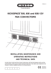
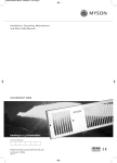
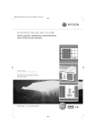
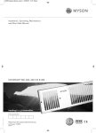
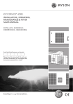
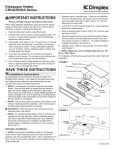
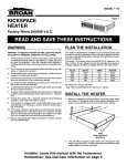
1370037 - 04
KICKSPACE
®
KICKSPACE 800
FAN CONVECTOR
O
INSTALLATION, MAINTENANCE AND
OPERATING INSTRUCTIONS
AND TECHNICAL DATA
PLEASE READ THESE INSTRUCTIONS THOROUGHLY BEFORE BEGINNING INSTALLATION
AFTER INSTALLATION LEAVE THESE INSTRUCTIONS WITH THE USER
LIST OF CONTENTS
1.
2.
Application ............................................................... Page 2
Electrical Supply ................................................................. 3
3.
4.
Preparation ......................................................................... 3
Water Connections ............................................................. 4
5.
6.
Fitting Kickspace ................................................................. 4
Completion .......................................................................... 5
7.
8.
Controls ............................................................................... 5
Operation ............................................................................ 6
9. Maintenance ....................................................................... 6
10. Technical Data .................................................................... 6
11. Wiring Diagrams ................................................................. 7
1. APPLICATION
1.1. System design
Kickspace 800 fan convectors must always be fitted to a two pipe pumped circulation central heating system.
For optimum performance, fan convectors require a continuous flow of hot water through the high efficiency heat
exchanger. If used in conjunction with radiators it is preferable to provide a separate circuit for the fan convectors to
ensure an adequate flow of water in accordance with the technical data given in section 10 (page 6).
Fig. 1 shows an example of a system combining fan convectors and radiators. The pump runs continuously while the
system is in operation.
The fan convectors may be controlled by individual room thermostats, and the radiators may be controlled by one or
more zone valves via room thermostats, or by individual thermostatic radiator valves.
Systems with thermostatic control which switches the circulating pump will affect the fan convector function as the flow
of water will be interrupted.
If a separate circuit cannot be provided for the Kickspace, its position should be chosen, and the system should be
balanced, to ensure sufficient water flow is provided. Low water flow will be indicated by the unit switching off by its
internal water temperature thermostat when the fan and pump are running together.
1.2. Selection
It is preferable to select on the basis of maintaining the calculated heat losses of the room when operating at Low fan
speed at 60°C temperature difference. This will enable the Boost fan speed to be used for more rapid warming from cold
in extreme conditions.
The mean water temperature should not be below 60°C for satisfactory operation.
1.3. Location
Kickspace 800 units are intended for installation in the cavity beneath cupboards on the vacant floor space. In this
position, consideration should be given to the storage of perishable goods in the cupboard above.
No rear access shall be available to the unit after completion of installation.
Room
thermostat 1
Kickspace 1
Kickspace 2
(manual control)
Boiler
Radiator 1
Radiator 3
Radiator 2
TRV
Room
thermostat 2
Fig. 1 - System design
2
2. ELECTRICAL SUPPLY
WARNING: THIS APPLIANCE MUST BE EARTHED.
2.1 The Kickspace 800 is supplied fitted with a 2 metre 0.75 mm² cord.
2.2 A fused electrical spur with a switch having 3 mm separation on all poles must be provided in an easily
accessible position adjacent to the Kickspace, as shown in Fig. 2.2.
2.3 Room Thermostat - If a room thermostat is to be fitted, wire it at this stage. See wiring diagram on page 7.
2.4 Remote Control Switch - A Remote Control Switch is available as an accessory, and if required should be
wired at this stage.
Remote Controls kits for the Kickspace 500 and 600 are suitable for the Kickspace 800. Follow the
instructions supplied with the kit, connecting the cable supplied as follows:Yellow lead to spare side of terminal block position '1'
Brown lead to spare side of terminal block opposite position 'L'
Red lead to spare side of terminal block position '3'
Green/Yellow (Brass or Chrome switch only) connect to terminal block position '
'
Do not energize the electrical supply until the remaining stages of the installation have been completed.
ELECTRICAL SUPPLY - continued
3. PREPARATION
3.1 A clean and level floor area is required under
the cupboard base.
3.2 Floor mounting - The Kickspace is normally
fitted directly onto the floor. Four mounting feet
are fitted to the base of the unit.
Switched fused spur
Decide the position of the Kickspace, mark out
and cut the plinth to the dimensions as shown in
Fig. 3.2.
3.3 Plinth mounting - As an alternative to floor
mounting the unit may be fitted into the plinth.
For this application cut the plinth to the
dimensions as shown in Fig. 3.3.
Kickspace
A suitable support must be securely fitted to
the floor. The top of the support must be level
with the lower edge of the cut-out when fitted.
3.4 A minimum of 25 mm clear headroom is
required above the top of the Kickspace
when fitted.
Fig. 2.2 - Electrical supply
PREPARATION - continued
3.5 Flexible connection hoses with integral isolating valves are supplied to allow for easy installation and future
access for maintenance etc.
575 mm
Base of cupboard
100 mm
575 mm
100 mm
Fig. 3.2 - Plinth opening (floor mounting)
Fig. 3.3 - Plinth opening (plinth mounting)
3
4. WATER CONNECTIONS
WATER CONNECTIONS - continued
4.1 Connect flexible pipes to the system flow and
return pipes.
4.2 Connect the valve ends of the flexible pipes to
the rear of the Kickspace.
Note: The direction of flow arrows on the valves
are not significant in this application.
System pipework
Flexible pipes
Isolating valves
Flexible pipes
Fig. 4.1 - Connect flexible pipes to system pipework
Fig. 4.2 - Connect the flexible pipes to the Kickspace
WATER CONNECTIONS - continued
5. FITTING THE KICKSPACE
4.3 Fill and vent the system. A vent screw is
provided to vent the Kickspace heat exchanger.
5.1 Position the Kickspace under the cupboard in the
required location, with the front edge just behind
the line of the plinth.
Close the vent and check for leaks.
Note: Ensure that the flexible pipes are not kinked and
that the electrical cord is not in contact with hot surfaces.
Air vent screw
Front view of unit
Fig. 5.1 - Position the Kickspace
Fig. 4.3 - Vent screw position
FITTING THE KICKSPACE - continued
5.2 Replace the plinth and bring the Kickspace forward into the opening so that the front edge projects 8 mm through
the plinth.
Top view of unit
8 mm projection
Fig. 5.2 - Ensure 8 mm projection
4
6. COMPLETION
COMPLETION - continued
6.1 Align the grille and secure it to the unit with two
screws supplied (use the shorter screws).
6.2 Secure the unit/grille to the plinth with two
screws supplied (use the longer screws).
It is essential that both sets of screws are used.
Front view of unit
Front view of unit
O
O
Unit securing screws (long)
Grille securing screws (short)
Fig. 6.1 - Fit the grille
Fig. 6.2 - Secure the unit to the plinth
6.3 Complete the electrical supply, switch on and
test the Kickspace.
7. CONTROLS
O
Switch for fan
Boost
Off
Low
Summer/Winter
switch
Fig. 7 - Controls
5
8. Operation
Ensure that the electrical supply is switched on.
8.1. Winter use - for heating
If remote room thermostat is fitted, turn it to a high setting.
Set the Summer/Winter switch to the winter position by pressing it to the red top disc.
Set the fan speed switch to Boost (
) or Low (
), see Fig. 7.
The fan will now rotate provided hot water is circulating through the heat exchanger at or above 43°C.
If the unit has just been opened to the heating system or the system is not up to working temperature, there will be a
delay before the fan begins to run.
8.2. Temperature control
If a room thermostat is connected to control the Kickspace, its setting should be gradually adjusted to obtain the
required temperature. Use the fan speed switch at Boost ( ) or Low ( ) as required to increase or decrease the heat
output of the unit.
8.3. Time switch control
It is normal for a heating system to be controlled by a programmer or time switch. Under such control the internal low
temperature thermostat in the Kickspace ensures that the fan will stop after the heating system is switched off and the
water flow stops. It will automatically restart, if left in an operating position, when the heating system is reheated.
8.4. Summer use - for air circulation
If required, the Kickspace can be used in Summer for air circulation without heat. Set the Summer/Winter switch to the
Summer position by pressing to the blue bottom disc.
If a remote thermostat is fitted, set it to its highest setting.
In this position the fan will run at the selected fan speed until manually reset.
8.5. Remote control switch
If a Remote Control Switch is fitted, the fan speed switch on the unit will be inoperative.
Refer to the instructions supplied with the Remote Control Switch for further details.
9. MAINTENANCE
Isolate the electrical supply.
Maintenance should be restricted to occasional removal of dust and lint around the unit. In severe conditions, remove the top
cover and gently remove dust with a soft brush and vacuum cleaner, taking care not to damage the fan or heat exchanger.
Do not tamper with any electrical parts.
In case of further service requirements, contact your supplier.
10. TECHNICAL DATA
Heat outputs with flow rate 75 g/h. Tested in accordance with BS 4856 Pt 1.
Motor Water
Fan
power content speed
(Watts) (litres)
40
Maximum heat output (Btu/h)
Temperature difference (°F)
Maximum heat output (Watts)
Temperature difference (°C)
40°
45°
50°
55°
60°
65°
72°
81°
90°
99°
108°
117°
Boost
1736
1964 2192 2420 2649 2879 5930 6701 7479 8257 9038
9823
Low
1396
1552 1707 1860 2012 2162 4763 5295 5824 6346 6865
7377
0.18
18
Flow rate correction factors:
453 l/h (100 g/h) multiply output by 1.03, 227 l/h (50 g/h) multiply output by 0.96, 113 l/h (25 g/h) multiply output by 0.89
Approximate hydraulic resistance through fan convector
gallons/h
ft wg
mm wg litres/h
100
1.35
411
455
75
50
0.81
0.40
248
122
340
227
25
0.12
36
113
Test pressure: 20 bar
Maximum working pressure: 10 bar
Water connections: 15 mm compression
Electrical supply: 220 - 240 V ~ 50 Hz
6
11. WIRING DIAGRAMS
Kickspace 800 - standard wiring diagram
Summer/Winter
switch
Motor
Terminal block
g/y
Low
temperature
cut-out
bl
br
y
bl
bl
N
L
Mains
supply
y
1
2
3
bl
r
br
bl
r
Fan speed
switch
br
y
Kickspace 800 - with external room thermostat
Room
thermostat
Mains
supply
Summer/Winter
switch
Motor
Terminal block
g/y
g/y
Low
temperature
cut-out
bl
br
y
bl
bl
y
1
2
3
bl
r
Fan speed
switch
bl
br
N
L
br
bl
r
br
y
Kickspace 800 - with white remote control switch
Summer/Winter
switch
TOP
L1 L3 L2
Motor
Terminal block
Low
temperature
cut-out
L3 L2
g/y
bl
br
y
bl
L1
bl
bl
r
br
y
r
N
L
Mains
supply
y
1
2
3
br
bl
Kickspace 800 - with brass or chrome remote control switch
y
TOP
COM
L1
r
Motor
Low
temperature
cut-out
L2
L1 L2
g/y
bl
COM
g/y
Summer/Winter
switch
bl
br
g/y
Terminal block
bl
br
y
bl
r
N
L
Mains
supply
1
2
3
y
br
bl
Colour code: br-Brown, bl-Blue, r-Red, y-Yellow, g/y-Green/Yellow
7
USEFUL TELEPHONE NUMBERS
Literature
Training
For copies of the latest Convector range brochure, price
lists, full installation instructions and other Potterton
Myson product literature, contact the Brochure Hotline
on 0345 697509.
Fully equipped Training Centres around the country offer
a wide range of courses to installers. For details call
01926 430481.
Sales Operations
After Sales Service
A national team of field service engineers and spare
parts stockists are available to support the products. For
service call 08706 096096 or for details of your nearest
spare parts stockist call 01926 880640.
We offer on-line sales order processing with direct client
access and a national network of sales representatives.
Call 0191 4917500 for further information. For export
sales contact 01482 7011709.
Warranty
Technical Advisory Service
For immediate help or advice on any aspect of
installation or maintenance call 08706 049049.
Every Myson convector carries a free 5 year parts and
labour warranty. In accordance with our policy of
continual product improvement, we reserve the right to
amend the specification of these products without prior
notification.
Please ensure that the enclosed Warranty Registration
card is completed and returned within seven days.
POTTERTON MYSON LIMITED, REGISTERED IN ENGLAND NO. 412935.
REGISTERED OFFICE: 84 ECCLESTON SQUARE, LONDON SW1V 1PX.
All descriptions and illustrations contained in this manual have been carefully prepared but we reserve the right to make changes and improvements in our
products which may affect the accuracy of the information contained in this manual. The statutory rights of the consumer are not affected.
© Potterton Myson Limited 1998. All rights reserved. No part of this manual may be reproduced by any means without prior written consent.
Manual compiled and designed by Publications 2000 (01670) 356525
06/98/D108