1
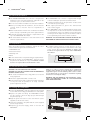
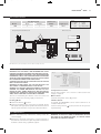
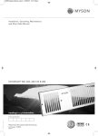
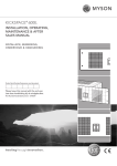
23042 Kickspace Manual 15/02/2012 11:23 Page 2
Installation, Operating, Maintenance
and After Sales Manual.
KICKSPACE ® 500E
heatingthroughinnovation.
Product Serial Number:
Please leave this manual with the end user.
Part Number: 1370066
Issue 2
23042 Kickspace Manual 15/02/2012 11:23 Page 3
02
KICKSPACE ® 500E
1.0 General Information
l This MYSON KICKSPACE ® fan convector is designed for
installation in the cavity beneath kitchen cupboards on the
vacant floor space, or other similar locations.
l No rear access shall be available to the unit after installation.
l Before proceeding with the installation, the unit must be
correctly sized to meet the heat loss requirements of
the room.
l When installed under a kitchen unit consideration should be
given to storage of perishable goods in the cupboard above.
l A minimum of 25mm clear headroom is required above the
top of the KICKSPACE® when fitted.
l The unit should be mounted on a clean and level floor area
under the cupboard base.
l The KICKSPACE ® fan convector is supplied with integral
controls including fan speed selector/winter switch.
l In summer mode the fan can be operated to circulate a flow
of air without any heat supply.
l Heat output performance is given in the Technical Data
section of this manual.
l Since KICKSPACE® units are supplied with fan speed control
it is important to size the unit to match the calculated heat
loss requirements of the room with the unit operating at the
low fan speed. The higher fan speed can then be used for
more rapid heating from cold in extreme conditions.
WARNING: THIS APPLIANCE MUST NOT BE INSTALLED IN A
BATHROOM OR OTHER SIMILAR HIGH HUMIDITY AREA.
2.0 Preparation
Before proceeding with the installation, unpack the carton
contents and check against the checklist below:
1. KICKSPACE® unit.
2. Instruction manual.
l A suitable support must be securely fitted to the floor.
The top of the support must be level with the lower edge
of the cut-out when fitted. A minimum of 25mm clear
headroom is required above the top of the KICKSPACE ®
when fitted.
3. Warranty card.
4. Grill.
Fig. 1
496
l A clean and level floor is required under the cupboard base.
99
l Decide the position of the KICKSPACE ®, mark out and cut
the plinth to the dimensions of fig. 1. A minimum of 25mm
clearance is required above the finished floor level.
25
3.0 Electrical Connection
WARNING: THIS APPLIANCE MUST BE EARTHED.
WARNING: THIS UNIT MUST NOT BE INSTALLED IMMEDIATELY
BELOW A SOCKET OUTLET.
l The electrical installation must comply with local or national
wiring regulations.
l This unit is supplied fitted with a 2 metre cord.
l A fused electrical spur with a switch having 3mm separation
on all poles must be provided in an easily accessible
position adjacent to the unit.
Caution: In order to avoid a hazard due to inadvertent
resetting of the thermal cut-out, this appliance must not be
supplied through an external switching device such as a timer
or room thermostat, or connected to a circuit that is regularly
switched on and off by the utility.
WARNING: DO NOT ENERGISE THE ELECTRICAL SUPPLY
UNTIL THE REMAINING STAGES OF THE INSTALLATION
HAVE BEEN COMPLETED.
4.0 Fitting the KICKSPACE ®
l Position the KICKSPACE® under the cupboard in the required
location with the front edge just behind the line of the plinth.
Fig. 2
l Replace the plinth and bring the KICKSPACE ® forward
into the opening so the front edge projects 8mm through
the plinth (see fig. 2).
l Align the grille and secure it to the unit with two screws
supplied (use the shorter screws).
l Secure the unit/grille to the plinth with two screws supplied
(use the longer screws).
8mm Projection
l Complete the electrical supply, switch on and test the
KICKSPACE®.
Grille Securing Screws
Unit Securing Screws
23042 Kickspace Manual 15/02/2012 11:23 Page 4
KICKSPACE ® 500E
03
5.0 Technical Data
Heat Output (kW)
Model
Boost
Normal
Rated Power
(Watts)
2
1
2025
500E
Supply Cord
1.0mm2
Wiring Diagram KICKSPACE ® 500E
Key:
br - Brown
bl - Blue
r - Red
p - Purple
y - Yellow
g/y - Green/Yellow
Dimensions (mm)
Fan
N
View on arrow
L
Cable entries
g/y
bl
bl
br
y
g/y
p
93
br
Mains Cable
Top view
br
br
203
177
Heating Switch
Thermal Trip
r
r
321
Power Selector
Switch
p
y
Electric Element
p
FRONT GRILLE
y
bl
Fan Speed
Switch
br
101
br
View Switches
from Front
496
N.B: Add 4.5mm to the chassis height to allow for rubber mountings and screws.
6.0 Operating Instructions
WARNING: THIS APPLIANCE IS NOT INTENDED FOR USE BY
PERSONS (INCLUDING CHILDREN) WITH REDUCED PHYSICAL,
SENSORY OR MENTAL CAPABILITIES, LACK OF EXPERIENCE OR
KNOWLEDGE, UNLESS THEY HAVE BEEN GIVEN SUPERVISION
OR INSTRUCTION CONCERNING THE USE OF THE APPLIANCE
BE A PERSON RESPONSIBLE FOR THEIR SAFETY.
CHILDREN SHOULD ALSO BE SUPERVISED SO THAT THEY DO
NOT PLAY WITH APPLIANCE.
WARNING: DO NOT COVER THE UNIT OR OBSTRUCT THE
GRILLE AREA. IF COVERED THERE IS A RISK OF FIRE.
WARNING: THIS HEATER IS NOT EQUIPPED WITH A DEVICE TO
CONTROL THE ROOM TEMPERATURE. DO NOT USE THIS
HEATER IN SMALL ROOMS WHEN THEY ARE OCCUPIED BY
PERSONS NOT CAPABLE OF LEAVING THE ROOM ON THEIR
OWN, UNLESS CONSTANT SUPERVISION IS PROVIDED.
Fig. 3
Heating Switch
Power Selector
Switch
Fan Speed Switch
Temperature Control
Use the Power switch I or II to increase or decrease the heat
output, as required.
This unit is controlled by the switches on the front of the unit
(see fig. 3). Ensure the electricity supply is switched on.
Off Position
Heating Mode
Summer Mode
l Set the fan switch to
position.
l Set the power switch to the I or II position as required. The fan
will operate at the appropriate speed for the element selected.
The fan speed switch does not operate in these Conditions.
Set the Heating switch to the (O) position.
If required, the KICKSPACE ® can be used in Summer for air
circulation without heat.
Set the heating switch to
required setting.
position,and set the fan speed to
7.0 Maintenance
l Before undertaking any maintenance activity isolate the
electrical supply.
l Maintenance should be restricted to occasional removal of
dust and lint around the front grille. Any further maintenance
should be carried out by a qualified engineer.
WARNING: IF THE SUPPLY CORD IS DAMAGED IT MUST BE
REPLACED BY THE MANUFACTURER, ITS SERVICE AGENT
OR OTHER RESPONSIBLE PERSON.
23042 Kickspace Manual 15/02/2012 11:22 Page 1
MYSON Eastern Avenue, Team Valley, Gateshead, Tyne & Wear NE11 0PG, UK
T: 0845 402 3434, F: 0191 491 7568, [email protected], www.myson.co.uk
Serial number
location
Serial number label
visible through grille
heatingthroughinnovation.
After Sales Service:
Spare parts and technical help on all Convector products are available from MYSON Service.
01.02.2012 ISSUE 2
MYSON Service, Somerden Road, Hull, East Yorkshire HU9 5PE
T: 01482 713927, F: 01482 789056, [email protected]