1
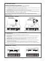
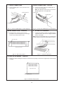
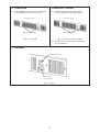
1370036 - 05
®
KICKSPACE 500, 600 and 600-12V
FAN CONVECTORS
INSTALLATION, MAINTENANCE AND
OPERATING INSTRUCTIONS
AND TECHNICAL DATA
PLEASE READ THESE INSTRUCTIONS THOROUGHLY BEFORE BEGINNING INSTALLATION.
AFTER INSTALLATION LEAVE THESE INSTRUCTIONS WITH THE USER AND COMPLETE THE
PRODUCT SERIAL NUMBER DETAILS IN THE BOX BELOW.
B.E.A.B.
Approved
LIST OF CONTENTS
1.
2.
Application ............................................................... Page 2
Electrical Supply ................................................................. 3
3.
4.
Preparation ......................................................................... 3
Water Connections ............................................................. 4
5.
6.
Fitting Kickspace ................................................................. 4
Completion .......................................................................... 5
7.
8.
Controls ............................................................................... 5
Operation ............................................................................ 6
9. Maintenance ....................................................................... 6
10. Technical Data .................................................................... 7
11. Wiring Diagrams ................................................................. 7
1. APPLICATION
1.1. System design
Kickspace fan convectors must always be fitted to a two pipe pumped circulation central heating system.
For optimum performance, fan convectors require a continuous flow of hot water through the high efficiency heat
exchanger. If used in conjunction with radiators it is preferable to provide a separate circuit for the fan convectors to
ensure an adequate flow of water in accordance with the technical data given in section 10 (page 7).
Fig. 1 shows an example of a system combining fan convectors and radiators. The pump runs continuously while the
system is in operation.
The fan convectors may be controlled by individual room thermostats, and the radiators may be controlled by one or
more zone valves via room thermostats, or by individual thermostatic radiator valves.
Systems with thermostatic control which switches the circulating pump will affect the fan convector function as the flow
of water will be interrupted.
If a separate circuit cannot be provided for the Kickspace, its position should be chosen, and the system should be
balanced, to ensure sufficient water flow is provided. Low water flow will be indicated by the unit switching off by its
internal water temperature thermostat when the fan and pump are running together.
1.2. Selection
When deciding on the model size, it is preferable to select the model on the basis of maintaining the calculated heat
losses of the room when operating at Low fan speed at 60°C temperature difference. This will enable the Boost fan
speed to be used for more rapid warming from cold in extreme conditions.
The mean water temperature should not be below 60°C for satisfactory operation.
1.3. Location
Kickspace units are intended for installation in the cavity beneath kitchen cupboards on the vacant floor space. In this
position, consideration should be given to the storage of perishable goods in the cupboard above.
Kickspace 600-12V units are suitable for installation in bathrooms beneath a bath or cupboard, but may be used in
locations where the extra safety of low voltage operation is seen to be advantageous.
No rear access shall be available to the unit after completion of installation.
Room
thermostat 1
Kickspace 1
Kickspace 2
(manual control)
Boiler
Radiator 1
Radiator 3
Radiator 2
TRV
Room
thermostat 2
Fig. 1 - System design
2
2. ELECTRICAL SUPPLY
WARNING: THIS APPLIANCE MUST BE EARTHED.
The electrical installation must comply with local or national Regulations.
2.1 The Kickspace is supplied fitted with a 2 metre 0.75 mm² cord.
2.2 A fused (2A) electrical spur with a switch having 3 mm separation on all poles must be provided in an easily
accessible position adjacent to the Kickspace, as shown in Fig. 2.2.
2.3 Room Thermostat - If a room thermostat is to be fitted, wire it at this stage. Remove the link in terminals T1
and T2. Connect sufficient cord to these terminals and connect to the thermostat.
2.4 Remote Control Switch - A Remote Control Switch is available as an accessory, and if required should be
wired at this stage. Follow the instructions supplied with the kit.
Do not energize the electrical supply until the remaining stages of the installation have been completed.
Note: If the supply cord to the transformer is damaged, it must be replaced by a special cord/transformer assembly available
from Myson Convectors.
ELECTRICAL SUPPLY - continued
Kickspace 500 and 600
Kickspace 600-12V
Fig. 2.2 - Electrical supply
3. PREPARATION
3.1 A clean and level floor area is required under the cupboard or bath base.
3.2 Floor mounting - The Kickspace is normally fitted directly onto the floor. Four mounting feet are fitted to the
base of the unit.
Decide the position of the Kickspace, mark out and cut the plinth to the dimensions as shown in Fig. 3.2.
3.3 Plinth mounting - As an alternative to floor mounting the unit may be fitted into the plinth. For this
application cut the plinth to the dimensions as shown in Fig. 3.3.
3.4 A suitable support must be securely fitted to the floor. The top of the support must be level with the lower
edge of the cut-out when fitted.
A minimum of 25 mm clear headroom is required above the top of the Kickspace when fitted.
3.5 Flexible connection hoses with integral isolating valves are supplied to allow for easy installation and future
access for maintenance etc.
PREPARATION - continued
Base of cupboard
A
B
A
Kickspace 600, 600-12V 520
Kickspace 500
466
B
99
99
A
Kickspace 600, 600-12V 520
Kickspace 500
466
Fig. 3.2 - Plinth opening (floor mounting)
B
99
99
Fig. 3.3 - Plinth opening (plinth mounting)
3
4. WATER CONNECTIONS
WATER CONNECTIONS - continued
4.1 Connect flexible pipes to the system flow and
return pipes.
4.2 Connect the valve ends of the flexible pipes to
the rear of the Kickspace.
Note: The direction of flow arrows on the valves
are not significant in this application.
System pipework
Flexible pipes
Isolating valves
Flexible pipes
Fig. 4.1 - Connect flexible pipes to system pipework
Fig. 4.2 - Connect the flexible pipes to the Kickspace
WATER CONNECTIONS - continued
5. FITTING THE KICKSPACE
4.3 Fill and vent the system. A vent screw is
provided to vent the Kickspace heat exchanger.
5.1 Position the Kickspace under the cupboard in the
required location, with the front edge just behind
the line of the plinth.
Close the vent and check for leaks.
Note: Ensure that the flexible pipes are not kinked and
that the electrical cord is not in contact with hot surfaces.
Air vent screw
Front view of unit
Fig. 4.3 - Vent screw position
Fig. 5.1 - Position the Kickspace
FITTING THE KICKSPACE - continued
5.2 Replace the plinth and bring the Kickspace forward into the opening so that the front edge projects 8 mm through
the plinth.
Top view of unit
8 mm projection
Fig. 5.2 - Ensure 8 mm projection
4
6. COMPLETION
COMPLETION - continued
6.1 Align the grille and secure it to the unit with two
screws supplied (use the shorter screws).
6.2 Secure the unit/grille to the plinth with two
screws supplied (use the longer screws).
Front view of unit
Front view of unit
Unit securing screws
Grille securing screws
Fig. 6.1 - Fit the grille
Fig. 6.2 - Secure the unit to the plinth
6.3 Complete the electrical supply, switch on and
test the Kickspace.
7. CONTROLS
Summer/Winter switch
Switch for fan
Boost Off Low
Fig. 7 - Controls
5
8. Operation
Ensure that the electrical supply is switched on.
8.1. Winter use - for heating
If remote room thermostat is fitted, turn it to a high setting.
Set the fan speed switch to Boost or Low, see Fig. 7.
Set the Summer/Winter switch, see Fig. 7, to the Winter position by pressing to the red top disc.
The fan will now rotate provided hot water is circulating through the heat exchanger at or above 43°C.
If the unit has just been opened to the heating system or the system is not up to working temperature, there will be a
delay before the fan begins to run.
8.2. Temperature control
If a room thermostat is connected to control the Kickspace, its setting should be gradually adjusted to obtain the
required temperature. Use the fan speed switch at Boost or Low as required to increase or decrease the heat output of
the unit.
8.3. Time switch control
It is normal for a heating system to be controlled by a programmer or time switch. Under such control the internal low
temperature thermostat in the Kickspace ensures that the fan will stop after the heating system is switched off and the
water flow stops. It will automatically restart, if left in an operating position, when the heating system is reheated.
8.4. Summer use - for air circulation
If required, the Kickspace can be used in Summer for air circulation without heat. Set the Summer/Winter switch to the
Summer position by pressing to the blue bottom disc.
If a remote room thermostat is fitted, set it to its highest setting.
In this position the fan will run at the selected fan speed until manually reset.
8.5. Remote Control Switch
If a Remote Control Switch is fitted, the fan switch on the unit will be inoperative. Refer to the instructions supplied with the
Remote Control Switch for details.
9. MAINTENANCE
Isolate the electrical supply.
Maintenance should be restricted to occasional removal of dust and lint around the unit. In severe conditions, remove
the top cover and gently remove dust with a soft brush and vacuum cleaner, taking care not to damage the fan or heat
exchanger.
Do not tamper with any electrical parts.
In case of further service requirements, contact your supplier.
6
10. TECHNICAL DATA
Heat outputs with flow rate 75 g/h. Tested in accordance with BS 4856 Pt 1.
Model
Fan
Motor Water
power content speed
(Watts) (litres)
25
40°
45°
Boost
923
Low
50°
55°
60°
65°
72°
81°
90°
99°
108°
117°
1045
1166 1289 1412 1535 3152 3565 3981 4398 4817
5238
733
815
896
1056 1135 2501 2781 3058 3332 3603
3873
Boost
1275
1453 1630 1803 1975 2150 4350 4959 5561 6154 6738
7336
Low
880
1053 1225 1393 1560 1730 3002 3594 4179 4754 5322
5904
0.15
500
12
600 &
600-12V
Maximum heat output (Btu/h)
Temperature difference (°F)
Maximum heat output (Watts)
Temperature difference (°C)
40
976
0.30
29
Flow rate correction factors:
453 l/h (100 g/h) multiply output by 1.03, 227 l/h (50 g/h) multiply output by 0.96, 113 l/h (25 g/h) multiply output by 0.85
Noise level tests in accordance with EN 23741
Approximate hydraulic resistance through fan convector
gallons/h
ft wg
mm wg
75
500
0.58
600 & 600-12V
1.95
500
177
600 & 600-12V
594
50
25
0.22
0.05
1.06
0.48
68
14
323
146
litres/h
Model
Low
Boost
340
500
25.7
38.1
227
113
600 &
600-12V
29.4
39.0
Test pressure: 20 bar, Maximum working pressure: 10 bar
Water connections: 15 mm compression
Electrical supply: 220 - 240 V ~ 50 Hz
11. WIRING DIAGRAMS
Kickspace 500 and 600 - standard wiring diagram
Kickspace 600-12V - standard wiring diagram
Colour code: br-Brown, bl-Blue, bk-Black, r-Red, y-Yellow, g/y-Green/Yellow
7
Sound pressure at 2.5 m (dBA)
CUSTOMER SERVICE INFORMATION
After Sales Service
A dedicated customer service department backed up by a national network of service engineers is available to support
your Myson Convector.
Myson service can be contacted by:
Customer Service Working Hours:
Telephone: 01482 713927
Monday to Thursday 9am to 5pm
Facsimile: 01482 789056
Friday 9am to 3pm
E-mail: [email protected]
Technical Advisory Service
Spare Part Availability
For immediate help or advice on any aspect of
installation or maintenance call 01482 713927 or
E-mail: [email protected]
For details of how to obtain genuine Myson spare parts
call 01482 713927 or
E-mail: [email protected]
Product Warranty
Product Literature
Every Myson convector carries a free 5 year parts and
labour warranty. In accordance with our policy of
continual product improvement, we reserve the right to
amend the specification of these products without prior
notification.
For copies of the latest convector range brochure, price
lists, installation instructions and other Myson product
literature, contact the brochure hotline on 08457 697509
or access the Myson website: www.myson.co.uk
Customer Service Pledge
Sales Operations
Myson's offer on-line sales order processing with direct
client access and a national network of sales
representatives. Call 0191 491 7500 for further
information. For export sales contact 01482 7011709.
It is our aim to provide an immediate solution to your
service, technical and spare parts needs. However, if
further investigation is required and we say that we will
call you back, then you can be assured that we will call
you back.
SERIAL NUMBER LOCATION
MYSON RADIATORS LIMITED, REGISTERED IN ENGLAND NO. 653648.
REGISTERED OFFICE: EASTERN AVENUE, TEAM VALLEY TRADING ESTATE, GATESHEAD NE11 0PG.
All descriptions and illustrations contained in this manual have been carefully prepared but we reserve the right to make changes and improvements in our
products which may affect the accuracy of the information contained in this manual. The statutory rights of the consumer are not affected.
© Myson Radiators Limited 2002. All rights reserved. No part of this manual may be reproduced by any means without prior written consent.
Manual compiled and designed by Publications 2000 (01670) 356211
06/02/D94