1
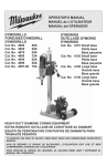
OPERATOR'S MANUAL
MANUEL de L'UTILISATEUR
MANUAL del OPERADOR
DYMODRILLS
FOREUSES DYMODRILL
DYMODRILLS
DYMORIGS
OUTILLAGE DYMORIG
DYMORIGS
Cat. No.
Cat. No.
Cat. No.
Cat. No.
Cat. No.
Cat. No.
Cat. No.
Cat. No. 4115 Small base
Petite base
Base pequeña
Cat. No. 4125 Small base
Petite base
Base pequeña
Cat. No. 4120 Large base
Grande base
Base grande
Cat. No. 4130 Large base
Grande base
Base grande
4004
4005
4079
4090
4094
4096
4097-20
20A
20A
20A
15A
20A
20A
15A
HEAVY-DUTY DIAMOND CORING EQUIPMENT
EXTRA ROBUSTE OUTILLAGE DE CAROTTAGE AU DIAMANT
EQUIPO DE PERFORACION CON PUNTAS DE DIAMANTE PARA
TRABAJOS PESADOS
TO REDUCE THE RISK OF INJURY, USER MUST READ AND UNDERSTAND OPERATOR'S
MANUAL.
AFIN DE RÉDUIRE LE RISQUE DE BLESSURES, L'UTILISATEUR DOIT LIRE ET BIEN
COMPRENDRE LE MANUEL DE L'UTILISATEUR.
PARA REDUCIR EL RIESGO DE LESIONES, EL USUARIO DEBE LEER Y ENTENDER EL
MANUAL DEL OPERADOR.
GENERAL POWER TOOL SAFETY WARNINGS
WARNING READ ALL SAFETY WARNINGS AND ALL INSTRUCTIONS. Failure
to follow the warnings and instructions may result in electric shock, fire and/or serious
injury. Save all warnings and instructions for future reference. The term "power
tool" in the warnings refers to your mains-operated (corded) power tool or battery-operated
(cordless) power tool.
attached to a rotating part of the power tool may
result in personal injury.
•Do not overreach. Keep proper footing and
balance at all times. This enables better control
of the power tool in unexpected situations.
•Dress properly. Do not wear loose clothing or
jewellery. Keep your hair, clothing and gloves
away from moving parts. Loose clothes, jewellery or long hair can be caught in moving parts.
•If devices are provided for the connection of
dust extraction and collection facilities, ensure
these are connected and properly used. Use of
dust collection can reduce dust-related hazards.
WORK AREA SAFETY
•Keep work area clean and well lit. Cluttered or
dark areas invite accidents.
•Do not operate power tools in explosive atmospheres, such as in the presence of flammable
liquids, gases or dust. Power tools create sparks
which may ignite the dust or fumes.
•Keep children and bystanders away while
operating a power tool. Distractions can cause
you to lose control.
ELECTRICAL SAFETY
•Power tool plugs must match the outlet. Never
modify the plug in any way. Do not use any
adapter plugs with earthed (grounded) power
tools. Unmodified plugs and matching outlets will
reduce risk of electric shock.
•Avoid body contact with earthed or grounded
surfaces such as pipes, radiators, ranges and
refrigerators. There is an increased risk of electric
shock if your body is earthed or grounded.
•Do not expose power tools to rain or wet conditions. Water entering a power tool will increase
the risk of electric shock.
•Do not abuse the cord. Never use the cord for
carrying, pulling or unplugging the power tool.
Keep cord away from heat, oil, sharp edges
or moving parts. Damaged or entangled cords
increase the risk of electric shock.
•When operating a power tool outdoors, use an
extension cord suitable for outdoor use. Use
of a cord suitable for outdoor use reduces the risk
of electric shock.
•If operating a power tool in a damp location
is unavoidable, use a residual current device
(RCD) protected supply. Use of an RCD reduces
the risk of electric shock.
POWER TOOL USE AND CARE
•Do not force the power tool. Use the correct
power tool for your application. The correct
power tool will do the job better and safer at the
rate for which it was designed.
•Do not use the power tool if the switch does not
turn it on and off. Any power tool that cannot be
controlled with the switch is dangerous and must
be repaired.
•Disconnect the plug from the power source
and/or the battery pack from the power tool
before making any adjustments, changing
accessories, or storing power tools. Such preventive safety measures reduce the risk of starting
the power tool accidentally.
•Store idle power tools out of the reach of children and do not allow persons unfamiliar with
the power tool or these instructions to operate
the power tool. Power tools are dangerous in the
hands of untrained users.
•Maintain power tools. Check for misalignment
or binding of moving parts, breakage of parts
and any other condition that may affect the
power tool’s operation. If damaged, have the
power tool repaired before use. Many accidents
are caused by poorly maintained power tools.
•Keep cutting tools sharp and clean. Properly
maintained cutting tools with sharp cutting edges
are less likely to bind and are easier to control.
•Use the power tool, accessories and tool bits
etc., in accordance with these instructions,
taking into account the working conditions and
the work to be performed. Use of the power tool
for operations different from those intended could
result in a hazardous situation.
PERSONAL SAFETY
•Stay alert, watch what you are doing and use
common sense when operating a power tool. Do
not use a power tool while you are tired or under
the influence of drugs, alcohol or medication. A
moment of inattention while operating power tools
may result in serious personal injury.
•Use personal protective equipment. Always
wear eye protection. Protective equipment such
as dust mask, non-skid safety shoes, hard hat, or
hearing protection used for appropriate conditions
will reduce personal injuries.
•Prevent unintentional starting. Ensure the
switch is in the off-position before connecting
to power source and/or battery pack, picking
up or carrying the tool. Carrying power tools with
your finger on the switch or energising power tools
that have the switch on invites accidents.
•Remove any adjusting key or wrench before
turning the power tool on. A wrench or a key left
SERVICE
•Have your power tool serviced by a qualified
repair person using only identical replacement
parts. This will ensure that the safety of the power
tool is maintained.
2
•WARNING: Some dust created by power sanding,
sawing, grinding, drilling, and other construction
activities contains chemicals known to cause
cancer, birth defects or other reproductive harm.
Some examples of these chemicals are:
• lead from lead-based paint
• crystalline silica from bricks and cement and
other masonry products, and
• arsenic and chromium from chemically-treated
lumber.
Your risk from these exposures varies, depending
on how often you do this type of work. To reduce
your exposure to these chemicals: work in a well
ventilated area, and work with approved safety
equipment, such as those dust masks that are specially designed to filter out microscopic particles.
SPECIFIC SAFETY RULES
•Diamond coring equipment requires the use
of water. When drilling overhead, use a liquid
collection system. Water in contact with the electrical system of the tool may make exposed metal
parts of the tool "live" and could give the operator
an electric shock.
•Operate power tool by insulated grasping surfaces, when performing an operation where the
cutting accessory may contact hidden wiring
or its own cord. Cutting accessory contacting a
"live" wire may make exposed metal parts of the
power tool "live" and could give the operator an
electric shock.
•Wear ear protectors when diamond drilling.
Exposure to noise can cause hearing loss.
•When the bit is jammed, stop applying downward pressure and turn off the tool. Investigate
and take corrective actions to eliminate the cause
of the bit jamming.
•When restarting a diamond drill in the workpiece check that bit rotates freely before
starting. If the bit is jammed, it may not start, may
overload the tool, or may cause the diamond drill
to release from the workpiece.
•When securing the drill stand with anchors and
fasteners to the workpiece, ensure that the anchoring used is capable of holding and restraining the machine during use. If the workpiece is
weak or porous, the anchor may pull out causing
the drill stand to release from the workpiece.
•When securing the drill stand with a vacuum
pad to the workpiece, install the pad on a
smooth, clean, non-porous surface. Do not
secure to laminated surfaces such as tiles
and composite coating. If the workpiece is not
smooth, flat or well affixed, the pad may pull away
from the workpiece.
•Ensure there is sufficient vacuum level before
drilling. If the vacuum level is insufficient, the pad
may release from the workpiece.
•Never perform overhead drilling with the
machine secured only by the vacuum pad. If
the vacuum is lost, the pad will release from the
workpiece.
•When drilling through walls or ceilings, ensure
to protect persons and the work area on the
other side. The bit may extend through the hole
or the core may fall out on the other side.
•Always use a liquid collection system when
drilling overhead. Water in contact with an electrical system of the tool may make exposed metal
parts of the tool "live" and could give the operator
an electric shock.
•Maintain tools carefully. Keep handles dry, clean
and free from oil and grease. Keep cutting edges
sharp and clean. Follow instructions for lubricating
and changing accessories. Periodically inspect tool
cords and extension cords for damage. Have damaged parts repaired or replaced by a MILWAUKEE
service facility.
•Maintain labels and nameplates. These carry
important information. If unreadable or missing,
contact a MILWAUKEE service facility for a free
replacement.
FUNCTIONAL DESCRIPTION
Shear pin model
2
8
1
3
1. Twist-lock plug
2. Cord
3. Gear shift lever
4. Water shut-off valve
5. Spindle sleeve
6. Retaining ring
7. Shear pin
8. Nameplate
7
4
5
6
Clutch model
2
6
1
3
1. Twist-lock plug
2. Cord
3. Gear shift lever
4. Water shut-off valve
5. Threaded spindle
6. Nameplate
5
3
4
GROUNDING
SYMBOLOGY
WARNING Improperly connecting the
grounding wire can result in the risk of electric shock. Check with a qualified electrician
if you are in doubt as to whether the outlet is
properly grounded. Do not modify the plug
provided with the tool. Never remove the
grounding prong from the plug. Do not use
the tool if the cord or plug is damaged. If
damaged, have it repaired by a MILWAUKEE
service facility before use. If the plug will not
fit the outlet, have a proper outlet installed by
a qualified electrician.
Amperes
Volts
Alternating Current
No Load Revolutions
per Minute (RPM)
Underwriters Laboratories, Inc.
United States and Canada
MILWAUKEE Dymodrills are provided with a 20
amp locking plug (NEMA L5-20). MILWAUKEE
meter boxes may be provided with either a 20 amp
locking or a 30 amp (NEMA L5-30) locking plug
depending on the model .
Grounded Tools:
Tools with Three Prong Plugs
Tools marked “Grounding Required” have a three wire cord
and three prong grounding plug.
The plug must be connected to
a properly grounded outlet (See Fig. A
Figures A and B). If the tool should
electrically malfunction or break
down, grounding provides a low
resistance path to carry electricity
away from the user, reducing the Fig. B
risk of electric shock.
The grounding prong in the plug is connected
through the green wire inside the cord to the
grounding system in the tool. The green wire in the
cord must be the only wire connected to the tool's
grounding system and must never be attached to
an electrically “live” terminal.
Your tool must be plugged into an appropriate outlet, properly installed and grounded in accordance
with all codes and ordinances. The plug and outlet
should look like those in Figures A and B.
Double Insulated Tools:
Tools with Two Prong Plugs
Tools marked “Double Insulated”
do not require grounding. They
have a special double insulation
system which satisfies OSHA
requirements and complies with
the applicable standards of Underwriters Laboratories, Inc., the Fig. C Fig. D
Canadian Standard Association and the National
Electrical Code. Double Insulated tools may be
used in either of the 120 volt outlets shown in
Figures C and D.
EXTENSION CORDS
Grounded tools require a three wire extension
cord. Double insulated tools can use either a two
or three wire extension cord. As the distance from
the supply outlet increases, you must use a heavier
gauge extension cord. Using extension cords with
inadequately sized wire causes a serious drop in
voltage, resulting in loss of power and possible tool
damage. Refer to the table shown to determine the
required minimum wire size.
The smaller the gauge number of the wire, the
greater the capacity of the cord. For example, a 14
gauge cord can carry a higher current than a 16
gauge cord. When using more than one extension
cord to make up the total length, be sure each cord
contains at least the minimum wire size required.
If you are using one extension cord for more than
one tool, add the nameplate amperes and use the
sum to determine the required minimum wire size.
Guidelines for Using Extension Cords
•If you are using an extension cord outdoors, be
sure it is marked with the suffix “W-A” (“W” in
Canada) to indicate that it is acceptable for outdoor
use.
•Be sure your extension cord is properly wired
and in good electrical condition. Always replace a
damaged extension cord or have it repaired by a
qualified person before using it.
•Protect your extension cords from sharp objects,
excessive heat and damp or wet areas.
Recommended Minimum Wire Gauge
For Extension Cords*
Extension Cord Length
Nameplate
Amperes
25'
50'
75'
100'
150'
0 - 2.0
2.1 - 3.4
3.5 - 5.0
5.1 - 7.0
7.1 - 12.0
12.1 - 16.0
16.1 - 20.0
18
18
18
18
16
14
12
18
18
18
16
14
12
10
18
18
16
14
12
10
--
18
16
14
12
10
---
16
14
12
12
----
WARNING To reduce the risk of injury,
always use a Ground Fault Circuit Interrupter
(GFCI) with diamond coring equipment to
reduce the risk of shock hazards. Always
position the GFCI as close as possible to the
power source.
* Based on limiting the line voltage drop to five volts at
150% of the rated amperes.
READ AND SAVE ALL
INSTRUCTIONS FOR FUTURE USE.
4
SPECIFICATIONS
Cat.
No.
4004
Motor
Amps Volts Protection
Speed
20
120
Clutch
Low - 300 High - 600
Suggested Diameters in
Medium Aggregate
Low - 7" - 14" High - 4" - 7"
4005
20
120
Clutch
Low - 600
High - 1200
Low - 4" - 7"
4079
20
120
Shear Pin
Low - 300
High - 600
Low - 7" - 14" High - 4" - 7"
High - 3/4" - 4"
4090
15
120
Shear Pin
Low - 375
High - 750
Low - 5" - 8"
4094
20
120
Shear Pin
Low - 450
High - 900
Low - 6" - 10" High - 2" - 6"
4096
20
120
Clutch
Low - 450
High - 900
Low - 6" - 10" High - 2" - 6"
4097-20
15
120
Clutch
Low - 500
High - 1000
Low - 3" - 5"
High - 2-1/2" - 5"
High - 1-1/4" - 3"
ASSEMBLY
For Cat. No. 4115 & 4120 only
WARNING To reduce the risk of injury,
Fig. 2
always unplug tool before changing or removing accessories. Only use accessories
specifically recommended for this tool. Others
may be hazardous.
Cradle assembly
Handle
spoke
Assembling Dymorigs & Vac-U-Rig® Stands
For Cat. No. 4125 & 4130 only
Column
Fig. 1
Handle
spoke
Leveling
screws (4)
Base
Cradle
assembly
Hex bolt
Column
bolts (2)
Lock washers
Column
1. Set the base on the ground.
2. Remove two (2) bolts and two (2) lockwashers
from accessory bag.
3. Place the column in the slot of the base.
4. Insert two (2) bolts and two (2) lockwashers and
tighten securely.
Moving the Handle to the Other Side
For Cat. Nos. 4125 & 4130 only
Base
Leveling
screws (4)
Socket set
screws (2)
Column bolts
1. Set the base on the ground. Loosen the hex bolt
and nut (wrench not supplied). Raise the column
upright.
2. To core vertically or horizontally, insert the
large column bolt (provided in separate accessory bag) through the bottom of column and into
the base. Tighten hex bolt and nut (wrench not
supplied).
To angle core, tilt the column to the desired
angle and tighten the hex bolt and nut. Save
the column bolt for future use when vertical or
horizontal coring.
3. Tighten the two (2) black socket set screws
located on the base with the supplied wrench.
4. Screw the four (4) handle spokes (provided in
separate accessory bag) into the hub on the
cradle assembly.
Fig. 3
Socket
screws (4)
Bubble level
Socket
screw
Ammeter
gauge
Meter
box
Cradle
5
Cradle
lock
Mounting the Dymodrill Motor to the Stand
For All Cat. Nos.
Dymorigs include a mounting bracket which mounts
Dymodrill motors to the stand. An optional spacer
assembly is available (see "Accessories"), which
can be used when coring with any bits; but it must
be used with any bit over 10" (outside diameter).
1. To mount the motor, loosen the cradle lock.
Raise the cradle on the column using the spoked
handle to allow room for installing the bit later.
Tighten the cradle lock.
NOTE: If the cradle is difficult to move on the
column, loosen the gib screws (see "Adjusting
the Gib Screws").
2. Fasten the mounting bracket or the optional
spacer assembly to the Dymodrill (Fig. 5) motor
using the four (4) 1/4"-20 threaded socket head
screws and four (4) lock washers (they are the
smaller of the two provided in separate accessory bag). Make sure the square key on the
mounting bracket or spacer assembly engages
with the slot on the Dymodrill motor.
3. Fasten the mounting bracket (or optional spacer
assembly) and motor assembly to the cradle slot
(Fig. 6) by inserting the four (4) 3/8"-16 threaded
socket head cap screws and lock washers (they
are the larger of the two provided in separate accessory bag) through the cradle. Place screws
through the holes from the other side of the
Dymorig and place lock washers on the side of
the mounting bracket.
After the Dymodrill motor is mounted, make sure the
cradle is rigid against the column to prevent the motor or bit from wobbling during coring. Before coring,
try to wiggle the cradle and motor with your hands.
If the cradle is secure, it should not move. If it does
move, tighten the gib screws that secure the cradle
to the column (see "Adjusting the Gib Screws").
1. Tighten the cradle lock.
2. Loosen the socket head screw and remove the
meter box.
3. Remove four (4) socket head screws holding the
spoked handle housing.
4. Turn the assembly around 180°.
5. Replace the four (4) socket head screws and
tighten securely.
6. Attach meter box to opposite side (see "Mounting
the Meter Box").
For Cat. Nos. 4115 & 4120 only
Socket screw
Fig. 4
and washer
Socket
Ammeter
screw
gauge
Meter
box
Cradle
Loosen the cradle lock.
Raise the cradle to the maximum height.
Lift the cradle an additional 1/2" by hand.
Tighten the cradle lock.
Loosen the socket head screw and remove the
meter box.
6. Remove the meter box stud from the cradle.
7. Remove the screw and washer from the end of
the pinion shaft.
8. Remove the handle and pinion shaft assembly.
9. Turn the assembly around 180° and insert into
cradle.
10. Replace the screw and washer and tighten
securely.
11. Replace the meter stud on the side opposite the
handle.
12. Attach meter box to opposite side (see “Mounting the Meter Box”).
13. Loosen the cradle lock and lower the cradle until
the pinion engages the rack.
14. Tighten the cradle lock.
1.
2.
3.
4.
5.
Fig. 5
Mounting the Meter Box
For All Catalog Nos.
A meter box is standard equipment with the Vac-URig®, but it must be purchased separately for other
Dymorigs (see "Accessories"). Attach the meter box
to the cradle on the side opposite of the handle.
1. Slip the collar on the meter box over the stud on
the cradle.
2. Position the meter box as desired and tighten
the 1/4"-20 threaded socket head screw.
NOTE: For horizontal (wall) coring, the ammeter
gauge must face upward in view of the operator.
Otherwise, water flow from the water shut-off
valve might drip into the outlets on the meter box.
Fig. 6
Slot
Adjusting the Gib Screws
After the motor is mounted, make sure the cradle
and motor are rigid against the column to prevent
the motor or bit from wobbling during coring. Before
coring, try to wiggle the cradle with your hands. If
the cradle is secure, it should not move. If it does
6
move, tighten the six (6) gib screws that secure the
cradle to the column as follows.
For Cat. No. 4125 & 4130 only.
Fig. 7
1. Remove the water shut-off valve components
from the accessory bag. (The copper washers
inside the bag are for bit installation.)
2. Insert the hose adapter into the hose nut. Then
insert the rubber washer into the hose nut.
3. Insert the hose nut assembly into the shut-off
valve and securely tighten the assembly with
the supplied socket wrench; some threads on
the hose adapter will still be exposed.
4. Screw the shut-off valve assembly into the water
swivel housing on the Dymodrill motor (Fig. 8).
Hand-tighten the assembly and then tighten it
approximately 1/4 turn with an adjustable wrench
(not provided).
Gib
Screws
Methods for Securing Equipment to Work
Surface
Tighten the six (6) gib screws with the hex wrench
(supplied in a separate accessory bag).
For Cat. No. 4115 & 4120 only.
To tighten the six (6) gib screws: loosen the hex nuts,
tighten the screws and then tighten the hex nuts.
WARNING To reduce the risk of injury
always secure the rig to the work surface to
help prevent personal injury and to protect
the rig. An unsecured rig could rotate during
coring and possibly cause injury.
Selecting and Installing a Core Bit (Fig. 8)
MILWAUKEE offers both standard and premium
Dymobits designed to cut through a variety of materials including poured concrete, steel-reinforced
concrete, and prestressed concrete. Always use
clean, sharp bits.
NOTE: Some building materials contain steel
reinforcements. MILWAUKEE Dymobits can cut
through embedded steel, but are not recommended
for coring solid steel plates.
Fig. 8
Horizontal Coring (walls)
For specific instructions on using anchors, see
"Using an Expansion-Type Anchor".
Water
Control
Valve
WARNING To reduce the risk of injury
always use an expansion-type anchor during
horizontal coring. Vacuum systems can slip
when used on a vertical surface.
Copper
Washer
Vertical Coring (floors)
Two methods will work to secure the rig for vertical coring: either an expansion-type anchor OR a
vacuum pump and vacuum pad system. Securing
the rig with an anchor gives better bit performance
because the attachment is more rigid. For specific
instructions on assembling the vacuum system,
see "Assembling and Using a Vacuum System".
1. To install a bit, grease the spindle and bit threads
to prevent corrosion and to help prevent the bit
from seizing on the threaded spindle.
2. Slip one copper washer (provided in separate
accessory bag with the water shut-off valve
components) onto the threaded spindle against
the spindle shoulder. The bag should contain an
extra copper washer; save it for future use.
3. Thread the bit securely onto the threaded spindle.
Optional Telescoping Assembly
The telescoping assembly can be used to supplement either securing method.
NOTE: Vac-U-Rig ® Cat. No. 4136 includes a
vacuum pump and vacuum pad. However, for some
applications, you may choose to use an expansiontype anchor to secure the tool.
Anchors and Telescoping Assembly are not supplied
with any of the above rigs. Telescoping Assembly
can be purchased separately (see “Accessories”).
Anchors unavailable through MILWAUKEE.
Selecting Speeds
Dymodrills operate in either high or low gear. Use
low speed for large diameter bits and high speed for
small diameter bits (see "Specifications").
Assembling the Water Shut-Off Valve to the
Dymodrill
Fig. 9
Hose nut
Rubber
washer
Attach to
Dymodrill
Shut-off valve
Hose adapter
7
One vacuum pad is supplied with the Vac-U-Rig®
and they can be purchased separately for other
Dymorigs. The vacuum pad is most effective when
it is secured to a relatively smooth surface such
as poured concrete. If the surface is too porous
or rough, the pad may not hold securely. Before
using a vacuum pad, always check the gasket on
the underside of the pad to make sure it isn't worn,
cracked or torn. If it is, immediately replace the
gasket, otherwise the vacuum pad may not hold the
rig securely. To replace the gasket, see "Replacing
Vacuum Pad Gaskets" in the "Maintenance" section. See "Accessories" for gasket part number.
1. To use the vacuum pad, tilt the base of the rig and
slide the vacuum pad under it so the threaded
stud goes through the hole on the end of the center slot on the base. Then set the stand upright.
2. Position the rig as required for coring the hole.
3. Level the rig with the four (4) leveling screws
using the bubble level (4125 & 4130 only) as a
guide. When the rig is level, tighten the four (4)
nuts (4125 & 4130 only) on the leveling screws.
4. Connect one end of the supplied vacuum hose
to the vacuum line coupler on the vacuum pad.
To do this, pull back the collar on the hose and
push the end of the hose onto the coupler until in
snaps into place. Then, connect the other end of
the vacuum hose to the coupler on the vacuum
pump following the same procedure.
5. The vacuum pump may be set on a dry surface
away from the rig or mounted to the base of the
Dymorig as shown. However, DO NOT mount the
vacuum pump to the Dymorig when angle coring.
To mount the vacuum pump on the Dymorig,
place the small hole on the vacuum pump mounting bracket over the vacuum pad stud on the
Dymorig.
6. Plug the vacuum pump into the power source—
the pump will start automatically. Step on the
vacuum pad or the vacuum pad stud until the vacuum pad lowers and adheres to the work surface.
7. After the pad is secured to at least 20 inches of mercury vacuum, tighten the vacuum pad nut securely.
OPERATION
Securing the Equipment to the Work Surface Using an Expansion-Type Anchor
For Catalog No. 4125 & 4130 only.
Fig. 10 Leveling
Screws
Rod or Bolt
Nut & Washer
or Vacuum
Pad Nut
Use a 5/8" expansion-type anchor (not supplied)
that will accept a 5/8" threaded rod or bolt to secure
the base to the work surface.
1. Level the stand with the four (4) leveling screws
using the bubble level as a guide. When the
stand is level, tighten the four (4) nuts on the
leveling screws.
2.Using an expansion-type anchor, insert a
threaded rod or bolt through the slot located on
the base of the Dymorig and tighten the bolt or
washer and nut firmly in the anchor following the
anchor manufacturer's instructions.
Assembling and Using a Vacuum System
For Catalog No. 4115, 4125 & 4130 only.
Fig. 11 Vacuum
Gauge
Small
Hole for
Attaching
Pump to
Dymorig
Stand
Filter Jar
Vacuum
Release
Valve
WARNING The vacuum gauge must
read a minimum of 20 inches of mercury
vacuum. To reduce the risk of injury DO NOT
CORE if the gauge reads less than 20 inches
of mercury vacuum.
Coupler
Fig. 12
Vacuum Hose
Using an Expansion-Type Anchor
For Cat. No. 4115 & 4120 only.
Use a 5/8" expansion-type
anchor (not supplied) that Fig. 13 Leveling Screws
will accept a 5/8" threaded
Rod or Bolt
rod or bolt to secure the
base to the work surface.
1. Remove the rubber
gasket from the base.
2. Level the rig with the
four (4) leveling screws.
3. Using an expansion-type anchor, insert a
threaded rod or bolt through the slot located in
the base of the Dymorig and tighten the bolt or
washer and nut firmly in the anchor following the
manufacturer's instructions.
Leveling
Screws
Vacuum
Pad Stud
Vacuum
Pad
Vacuum Pad Nut
Vacuum Line
Coupler
8
Assembling and Using a Vacuum System
For Cat. No. 4120 only.
Fig. 14
7. Tighten the four (4) leveling screws only enough
to eliminate rocking. Over-tightening can lift the
gasket off the ground and release the vacuum.
Filter Jar
Vacuum
Release
Valve
Small Hole
for Attaching
Pump to
Dymorig
Stand
Vacuum
Gauge
WARNING The vacuum gauge must
read a minimum of 20 inches of mercury
vacuum. To reduce the risk of injury DO NOT
CORE if the gauge reads less than 20 inches
of mercury vacuum.
Coupler
Vacuum
Hose
Using the Optional Telescoping Assembly
1. Secure the rig using either an expansion-type
anchor or a vacuum system (see "Securing the
Equipment to the Work Surface").
2. Place the top flange of the extension against
a ceiling or wall and place the other end
on the jack screw at the top of the Dymorig
column.
The assembly is adjustable up to 14 feet. Turn
the jack screw to tighten the assembly and to
make small adjustments.
Supply an Adequate Water Flow
An adequate supply of water must flow freely and
constantly during the entire cut. Dymodrills are
equipped with a built-in water shut-off valve to allow water to flow down the inside and up around
the outside of the bit. This acts to cool the bit and
flush cuttings from the hole.
Fig. 15
Vacuum
Pad
Gasket
Leveling
Screws
Vacuum Line
Coupler
Vacuum Adapter Assembly
Reading the Meter Box
The ammeter is
the dial indicator Fig. 16
on the meter box,
which is standard
equipment with
the Vac-U-Rig ®
and can be purc h a s e d s e p a - 20 Amp
rately for other Operating
Dymorigs. The Range
ammeter provides pressure
15 Amp Operating Range
feedback during
coring, allowing you to help prevent motor overload
and premature bit wear. The green area on the
ammeter is the operating range and the red area
indicates that you are applying too much pressure.
The vacuum pad is most effective when it is
secured to a relatively smooth surface such as
poured concrete.
If the surface is too porous or rough, the vacuum
pad may not hold securely. Before using the vacuum pad, always check the gasket on the underside
of the base to make sure it isn't worn, cracked or
torn. If it is, immediately replace the gasket, otherwise the vacuum may not hold the rig securely.
To replace the gasket, see "Replacing Vacuum
Pad Gaskets" in the "Maintenance" section. See
“Accessories" for gasket part number.
1. Position the rig as required for coring the hole.
2. Loosen the four (4) leveling screws until the ends
are above the bottom surface of the base.
3. Place the vacuum adapter assembly into the slot
in the base.
4. Connect one end of the supplied vacuum hose
to the vacuum line coupler on the vacuum base.
To do this, pull back the collar on the hose and
push the end of the hose onto the coupler until
it snaps into place. Connect the other end of the
vacuum hose to the coupler on the vacuum pump
following the same procedure.
5. The vacuum pump may be set on a dry surface
away from the rig or mounted to the base of the
Dymorig as shown. To mount the vacuum pump
on the base, place the small holes on the vacuum
pump mounting bracket over the two tapped
holes on the base. Attach the vacuum pump to
the base with two (2) 1/4" - 20 screws supplied
in the accessory bag.
6. Plug the vacuum pump into the power source - the
pump will start automatically. Step on the base
until it lowers and adheres to the work surface.
WARNING To reduce the risk of injury,
always use Dymodrills in conjunction with
meter boxes. Meter Boxes provide a switch
to turn the Dymodrill motor OFF and ON and
an optimum operation range to help prevent
motor overload.
Shear Pin and Clutch
Dymodrill Nos. 4079, 4090, and 4094 contain a
shear pin to protect the gear and motor against
overload. This pin drives the spindle sleeve. If the
bit binds, the pin will shear to prevent gear and
motor damage. Extra shear pins are supplied with
each Dymodrill and can be replaced (see "Accessories" for part numbers). It is important to check the
condition of the spindle before using the tool each
9
time. The spindle must be smooth without grooves
or pitting. If the spindle is not in good condition, it
is possible for the threaded spindle sleeve and the
internal spindle to weld together and seize during
coring (see "Lubricating the Spindle for Dymodrills
with a Shear Pin" in the "Maintenance" section for
spindle lubricating instructions).
Fig. 17
Shear Pin
Spindle Sleeve
(Shear pin models)
Threaded Spindle
(Clutch Models)
Retaining Ring
(shear pin model only)
Cat. Nos. 4004, 4005, 4096 and 4097 feature a
friction clutch rather than a shear pin to protect the
motor and gears. If the motor overloads, the clutch
will begin to slip and the bit will stop rotating. The
clutch is factory-set and does not require adjustment. Nuisance (frequent) clutch slippage should
be addressed by an authorized MILWAUKEE
service center.
WARNING To reduce the risk of injury,
always check the work area for hidden wires
before coring.
Coring Procedure
1. Select and install a bit following guidelines in
"Selecting and Installing a Core Bit".
2. Secure the rig to the work surface using one of
the methods described in "Methods for Securing
Equipment to Work Surface".
3. With the motor OFF, adjust the gear to either
high or low speed according to the guidelines in
"Selecting Speeds".
NOTE: DO NOT SHIFT SPEEDS WHEN THE
DYMODRILL MOTOR IS ON. To adjust the
speed on all Dymodrills, move the gear shift lever
to the desired setting.
Fig. 18
Gear Shift
Lever
5. If you are using a vacuum system, read the
instructions for specific setup in "Assembling
& Using a Vacuum System".
Do not continue the following steps until the
vacuum gauge reads at least 20 inches of
mercury vacuum. Never operate the Dymodrill
if the gauge reads less than 20 inches (see
"Mothods for Securing Equipment to Work
Surface"). Always monitor the vacuum gauge
during coring. If water collects in the vacuum
pump filter jar, empty it to prevent damage to
the pump.
WARNING To reduce the risk of injury,
do not operate the Dymorig if the gauge reads
less than 20 inches of mercury vacuum.
6. Turn the Dymodrill motor ON. Turn the water
on so it flows freely through the water shut-off
valve (see "Supply an Adequate Water Flow").
Turn the valve clockwise to increase water flow
and counterclockwise to decrease water flow.
7. While holding the handle, slightly loosen the
cradle lock handle and slowly rotate the handle to
lower the bit into the workpiece, applying steady,
even pressure. To help reduce bit wandering,
always use a light load to start the hole and wait
for the tip of the bit to penetrate the work surface
completely before increasing the load.
8. Use sufficient pressure so the bit cuts constantly.
Use the ammeter on the meter box as a guide
for proper pressure.
NOTE: If the rig shifts during coring, stop the
motor, reposition the rig and resume coring.
9. Monitor the water flow (see "Diamond Coring").
Generally, water should flow at a rate of approximately one to two gallons per minute. If
the water flow is too heavy, the two holes in the
water swivel housing will leak. If that happens,
reduce water flow. Water flow is adequate when
the water and cuttings are flushed in a circular
pattern about 1/2" around the bit. Keep the work
area dry.
10.When the cut is complete, keep the drill motor
ON and rotate the handle clockwise to remove
the bit. The bit may become stuck in the hole if
you turn the motor OFF before the bit is completely removed. Once the bit is removed from
the work surface, turn the motor OFF. Tighten the
cradle lock handle. Unplug the meter box from
the power supply before removing the vacuum
pump to prevent accidental starting of the motor
when the vacuum pump is released.
If you are using a vacuum pump, unplug it and
open the vacuum release valve to release the
vacuum.
Retrieving Cores and Deep Coring
When coring holes that are longer than the core bit,
follow the steps below.
1. Begin coring the hole as usual. When you have
cored to the length of the bit, stop the Dymodrill
4. Connect the water hose to the Dymodrill water
motor.
shut-off valve and to the water supply. Make 2. Remove the core by driving a chisel or slender
sure the seal is watertight. Use a standard
wedge into the cut between the core and the work
garden hose if you require additional length.
surface. You may also use a special core tongs,
Set up a water collection system.
bent wire or anchor bolts to remove the core.
10
Water Shut-Off
Valve
3. After removing the core, reinsert the bit or use a
bit extension and continue coring (see "Accessories"). Removing cores with diameters greater
than twice their length can be difficult. One
method to remove such cores is to first break
the core into smaller pieces and then remove
the pieces. Electric hammers and chisels are
ideal for breaking cores.
WARNING When coring through floors,
cores generally drop from the bit. To reduce
the risk of injury, provide proper protection
for people and property below the coring area.
Diamond Coring
Factors that influence diamond core performance:
•Amount of coolant
•Dymorig rigidity
•Dymorig condition
•RPM of drill motor
•Feed pressure applied to bit by operator
•Amount of steel
•Size of embedded steel
•Age of concrete
•Aggregate (size, type, hardness, abrasiveness)
•Type of sand–manufactured vs. river (natural)
•Operator technique
•Operator care
•Bit runout
Operator Technique
Core with consistent, firm feed pressure. Do not
subject the bits to sudden impacts. Uneven feed
rate cracks diamonds. Low feed pressure polishes
diamonds, slows penetration and contributes to bit
glazing. High feed pressure can overload the drill
motor or can cause diamonds to pull out prematurely, particularly when coring embedded steel.
Make the bit work, but do not try to jam the bit
through the material.
If vibration occurs:
1. Stop drilling.
2. Turn motor off.
3. Check for loose bolts, nuts and gib screws.
Tighten if required.
4. Check for bit runout. Replace if required.
If vibration continues to occur, remove the core and
loose material.
If vibration continues to occur after attempting these
measures, return the rig to the nearest MILWAUKEE service facility.
Water
Water provides two main benefits during coring:
1. Water acts as a coolant, eliminating the heat
caused by the friction of the coring action. This
preserves the integrity of the diamonds, the
bond matrix, the segment solder, and core tube.
Without a coolant, the heat buildup during coring
can cause all of these components to fail.
2. Water flushes loose, abrasive particles created
during coring. These particles consist of aggregate, sand, diamond particles and various
metals from embedded steel and the core bit
matrix. The hole must be free of debris to allow
the core bit to work. If loose particles are not
properly flushed from the hole, an unnecessary
drag will occur along the side of the core barrel.
This can contribute to bit glazing through lack of
power as well as motor damage through amperage increases due to bit resistance. In addition,
loose particles tend to wear the bit tube, which
can eventually result in the loss of segments.
Monitor water flow. Water volume should be adjusted until water return is a muddy, solid color.
Clear water or clear streaks indicate too much
water volume. Excess water is a leading cause of
bit glazing and failure. Other factors contribute to
glazing, but water adjustment is one of the most
easily controlled by the operator. Excessive water
prevents adequate segment/material contact.
When the bit segments do not properly contact the
work surface, the desired "controlled erosion" effect
which maintains bit sharpness does not occur and
the bit begins to glaze. This happens especially with
smaller diameter bits. Adequate water volume varies according to the bit diameter. Use only enough
water during coring to flush the cuttings from the
work surface.
Equipment
•Make sure machinery is in good operating condition. The column, carriage, motor connection and
base should all be firmly connected and should
not vibrate during coring.
•Motors should be of proper size (amperage and
RPM) for the diameter of the core bit used. Consult
motor guide in catalog.
•Always make sure the Dymorig is rigidly mounted
with an anchor or vacuum; any movement or vibration will shorten the life of the core bit. Standing on
the rig's base as a form of anchoring is dangerous
and does not provide the necessary rigidity.
Diamond Core Bits
•For the first 2 or 3 holes, use light feed pressure,
so the new diamond gradually breaks in.
•Lower the bit very slowly onto the work surface.
Use light feed pressure until the bit crown has
penetrated or "seated" into the material.
•If the core bit encounters embedded steel, slow
down the feed pressure and let the bit core at its
own pace. Don't force the bit. Typically the water
around the bit will clear when embedded steel is
encountered. Do not allow any vibration whatsoever or severe diamond breakage or pullout will
occur.
•Keep bits sharp.
Bit Glazing & Diamond Core Motor Shear Pins
Bit binding is caused by one of two things: a dull
(glazed) bit or a poorly stabilized rig.
Causes of bit glazing:
•Wrong RPM for bit diameter
•High feed pressure
•Low feed pressure
•High steel content in work surface
•Large, hard aggregate
•Too much water
•Low motor power
A sharp bit typically has good diamond exposure
and will cut/grind almost anything in its path, including embedded steel.
11
Sharpening Procedure for Core Bits
To work efficiently, diamond core bits must maintain good diamond exposure. Many factors work
together to provide the "controlled erosion" cycle of
the tool's segment to occur. When this "controlled
erosion" cycle is altered, the bit can become dull
or "glazed." Glazing becomes noticeable when
the coring feed rate slows dramatically or the bit
does not cut. Examine the bit immediately. If the
diamonds are flush with the metal, they are underexposed or "glazed."
The following steps will often correct the problem:
1. Reduce water flow until it becomes very muddy.
Continue using as little water as possible until
penetration increases.
2. If the bit does not open up, remove from hole.
Pour into the kerf a thick (1/4") layer of silica sand
(the coarser the better).
3. Resume drilling for approximately 3 to 5 minutes
with very little water and at a lower RPM if possible.
4. Gradually increase water flow to flush sand from
kerf.
5. Repeat as needed.
ACCESSORIES
WARNING To reduce the risk of injury,
always unplug the tool before attaching or
removing accessories. Use only specifically
recommended accessories. Others may be
hazardous.
For a complete listing of accessories refer to your
MILWAUKEE Electric Tool catalog or go on-line
to www.milwaukeetool.com. To obtain a catalog,
contact your local distributor or a service center.
The Effects of Steel in Coring
•To self-sharpen, diamond-impregnated core bits
require interaction with an abrasive material. This
abrasive material wears away the metal composition in the segment's matrix. As this is done, sharp
diamonds are exposed and the grinding action
created by the diamonds continues.
•Embedded metal (rebar) is not an abrasive material. It does not provide the degree of abrasiveness
required for matrix wear to occur and expose sharp
diamonds embedded in the segment's matrix.
•A high degree of exposure to embedded metal
by the bit's segments creates glazing. Glazing
prevents the bit from cutting and coring.
12
MAINTENANCE
WARNING To reduce the risk of injury,
always unplug your tool before performing
any maintenance. Never disassemble the tool
or try to do any rewiring on the tool’s electrical
system. Contact a MILWAUKEE service facility
for ALL repairs.
Maintaining Tools
Keep your tool in good repair by adopting a regular
maintenance program. Before use, examine the
general condition of your tool. Inspect guards,
switches, tool cord set and extension cord for damage. Check for loose screws, misalignment, binding
of moving parts, improper mounting, broken parts
and any other condition that may affect its safe operation. If abnormal noise or vibration occurs, turn the
tool off immediately and have the problem corrected
before further use. Do not use a damaged tool.
Tag damaged tools “DO NOT USE” until repaired
(see “Repairs”).
Under normal conditions, relubrication is not necessary until the motor brushes need to be replaced.
After six months to one year, depending on use,
return your tool to the nearest MILWAUKEE service
facility for the following:
•Lubrication
•Brush inspection and replacement
•Mechanical inspection and cleaning (gears, spindles, bearings, housing, etc.)
•Electrical inspection (switch, cord, armature, etc.)
•Testing to assure proper mechanical and electrical
operation
Lubricating Rack and Pinion
Maintain a light coat of MILWAUKEE Type "E"
Grease on the rack and pinion gears to reduce
friction and wear.
Lubricating the Spindle for Dymodrills with a
Shear Pin
Before each use, clean and lubricate the spindle or
spindle sleeve with MILWAUKEE Type "E" Grease
to prevent the spindle from seizing during coring.
1. To maintain the spindle on shear pin models,
remove the retaining ring with a screwdriver.
Then remove the spindle sleeve.
2. Remove dust and debris from the inside and outside diameter of the spindle and spindle sleeve
and from the water hole in the spindle. Place a
light coating of MILWAUKEE Type "E" grease on
the spindle.
3. Replace the spindle sleeve onto the spindle.
Make sure the spindle sleeve rotates freely on
the spindle. Then replace the retaining ring.
Replacing Vacuum Pad Gaskets
For Cat. No. 4115, 4125 & 4130 only.
Through normal use, the rubber gaskets on the
underside of the vacuum pads can become worn,
requiring replacement. If replacement is required,
take the pad to an authorized service center or
replace the gasket as follows:
1. Remove the old gasket and thoroughly remove
the old glue from the groove.
2. Squeeze a continuous bead of rubber cement (Cat.
No. 44-22-0060) in the entire bottom of the groove.
3. Immediately place a new gasket (Cat. No. 4344-0570) in the groove and press firmly in place.
4. Turn the pad over and place the gasket side on
a smooth flat surface and apply pressure to all
edges of the pad.
5. Allow cement to dry for 24 hours before using.
For Cat. No. 4120 only.
With normal use, the rubber gasket on the underside of the base can become worn, requiring
replacement. If replacement is required, take the
base to an authorized service center or replace the
gasket as follows:
1. Remove the motor and bit.
2. Tip the Dymorig on its back so that the wheels
point down.
3. Remove the old gasket.
4. Squeeze a continuous bead of rubber cement (Cat.
No. 44-22-0060) in the entire bottom of the groove.
5. Place the new gasket (Cat. No. 43-44-0605) into
the groove making sure it is pushed in completely.
6. Stand the Dymorig upright again.
7. Reinstall the motor and bit.
Cleaning the Filter on the Vacuum Pump
Periodically clean the filter felts to keep the vacuum
pump operating efficiently. To clean the filter felts,
remove the plastic jar and remove the felts from the
plastic tube. Remove dust and debris from the felts
and clean the plastic jar. Then replace the felts on
the plastic tube and position the jar
WARNING To reduce the risk of injury,
electric shock and damage to the tool, never
immerse your tool in liquid or allow a liquid
to flow inside the tool.
Cleaning
Clean dust and debris from vents. Keep the tool
handles clean, dry and free of oil or grease. Use
only mild soap and a damp cloth to clean your tool
since certain cleaning agents and solvents are
harmful to plastics and other insulated parts. Some
of these include: gasoline, turpentine, lacquer thinner, paint thinner, chlorinated cleaning solvents,
ammonia and household detergents containing
ammonia. Never use flammable or combustible
solvents around tools.
Repairs
If your tool is damaged, return the entire tool to the
nearest service center.
13
LIMITED WARRANTY - USA AND CANADA
Every MILWAUKEE power tool (including cordless product – tool, battery pack(s) - see separate & distinct
CORDLESS BATTERY PACK LIMITED WARRANTY statements & battery charger and Work Lights*) is warranted to the original purchaser only to be free from defects in material and workmanship. Subject to certain
exceptions, MILWAUKEE will repair or replace any part on an electric power tool which, after examination,
is determined by MILWAUKEE to be defective in material or workmanship for a period of five (5) years* after
the date of purchase unless otherwise noted. Return of the power tool to a MILWAUKEE factory Service
Center location or MILWAUKEE Authorized Service Station, freight prepaid and insured, is required. A copy
of the proof of purchase should be included with the return product. This warranty does not apply to damage that MILWAUKEE determines to be from repairs made or attempted by anyone other than MILWAUKEE
authorized personnel, misuse, alterations, abuse, normal wear and tear, lack of maintenance, or accidents.
*The warranty period for, Job Site Radios, M12™ Power Port, M18™ Power Source, and Trade Titan™ Industrial Work Carts is one (1) year from the date of purchase. The warranty period for a LED Work Light and LED
Upgrade Bulb is a limited LIFETIME warranty to the original purchaser only, if during normal use the LED bulb
fails the Work Light or Upgrade Bulb will be replaced free of charge.
*This warranty does not cover Air Nailers & Stapler, Airless Paint Sprayer, Cordless Battery Packs, Gasoline Driven
Portable Power Generators, Hand Tools, Hoist – Electric, Lever & Hand Chain, M12™ Heated Jackets, Reconditioned
product and Test & Measurement products. There are separate and distinct warranties available for these products.
Warranty Registration is not necessary to obtain the applicable warranty on a MILWAUKEE power tool product.
The manufacturing date of the product will be used to determine the warranty period if no proof of purchase is
provided at the time warranty service is requested.
ACCEPTANCE OF THE EXCLUSIVE REPAIR AND REPLACEMENT REMEDIES DESCRIBED HEREIN IS
A CONDITION OF THE CONTRACT FOR THE PURCHASE OF EVERY MILWAUKEE PRODUCT. IF YOU
DO NOT AGREE TO THIS CONDITION, YOU SHOULD NOT PURCHASE THE PRODUCT. IN NO EVENT
SHALL MILWAUKEE BE LIABLE FOR ANY INCIDENTAL, SPECIAL, CONSEQUENTIAL OR PUNITIVE
DAMAGES, OR FOR ANY COSTS, ATTORNEY FEES, EXPENSES, LOSSES OR DELAYS ALLEGED TO
BE AS A CONSEQUENCE OF ANY DAMAGE TO, FAILURE OF, OR DEFECT IN ANY PRODUCT INCLUDING, BUT NOT LIMITED TO, ANY CLAIMS FOR LOSS OF PROFITS. SOME STATES DO NOT ALLOW
THE EXCLUSION OR LIMITATION OF INCIDENTAL OR CONSEQUENTIAL DAMAGES, SO THE ABOVE
LIMITATION OR EXCLUSION MAY NOT APPLY TO YOU. THIS WARRANTY IS EXCLUSIVE AND IN LIEU
OF ALL OTHER EXPRESS WARRANTIES, WRITTEN OR ORAL. TO THE EXTENT PERMITTED BY
LAW, MILWAUKEE DISCLAIMS ANY IMPLIED WARRANTIES, INCLUDING WITHOUT LIMITATION ANY
IMPLIED WARRANTY OF MERCHANTABILITY OR FITNESS FOR A PARTICULAR USE OR PURPOSE;
TO THE EXTENT SUCH DISCLAIMER IS NOT PERMITTED BY LAW, SUCH IMPLIED WARRANTIES ARE
LIMITED TO THE DURATION OF THE APPLICABLE EXPRESS WARRANTY AS DESCRIBED ABOVE.
SOME STATES DO NOT ALLOW LIMITATIONS ON HOW LONG AN IMPLIED WARRANTY LASTS, SO
THE ABOVE LIMITATION MAY NOT APPLY TO YOU, THIS WARRANTY GIVES YOU SPECIFIC LEGAL RIGHTS, AND YOU MAY ALSO HAVE OTHER RIGHTS WHICH VARY FROM STATE TO STATE.
This warranty applies to product sold in the U.S.A. and Canada only.
Please consult the ‘Service Center Search’ in the Parts & Service section of MILWAUKEE’s website
www.milwaukeetool.com or call 1.800.SAWDUST (1.800.729.3878) to locate your nearest service facility for
warranty and non-warranty service on a Milwaukee electric power tool.
LIMITED WARRANTY - MEXICO, CENTRAL AMERICA AND CARIBBEAN
TECHTRONIC INDUSTRIES' warranty is for 5 year since the original purchase date.
This warranty card covers any defect in material and workmanship on this Power Tool.
To make this warranty valid, present this warranty card, sealed/stamped by the distributor or store where you
purchased the product, to the Authorized Service Center (ASC). Or, if this card has not been sealed/stamped,
present the original proof of purchase to the ASC.
Call toll-free 1 800 832 1949 to find the nearest ASC, for service, parts, accessories or components.
Procedure to make this warranty valid
Take the product to the ASC, along with the warranty card sealed/stamped by the distributor or store where
you purchased the product, and there any faulty piece or component will be replaced without cost for you. We
will cover all freight costs relative with this warranty process.
Exceptions
This warranty is not valid in the following situations:
a) When the product is used in a different manners from the end-user guide or instruction manual.
b) When the conditions of use are not normal.
c) When the product was modified or repaired by people not authorized by TECHTRONIC INDUSTRIES.
Note: If cord set is damaged, it should be replaced by an Authorized Service Center to avoid electric risks.
Model:
Date of Purchase:
Distributor or Store Stamp:
SERVICE AND ATTENTION CENTER
Rafael Buelna No.1.
Col. Tezozomoc Mexico, Azcapotzalco D.F.
Ph. 01 800 832 1949
IMPORTED AND COMMERCIALIZED BY:
TECHTRONIC INDUSTRIES MEXICO, .S.A. DE C.V.
Av. Santa Fe 481 piso 6, Col. Curz Manca.
CP 05349, Cuajimalpa, D.F.
14