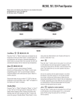
1
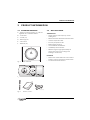
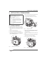
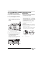
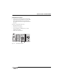
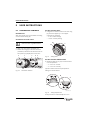
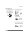
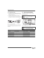
INSTALLATION & COMMISSIONING
4
INSTALLATION & COMMISSIONING
4. Align connector pins [F] into receptors [G] in
the circuit board and push fully home.
DANGER:
B 24V & 230V: Do not touch
electrical components or
circuits.
5. Feed the ribbon cable [G] into recess [H].
B Isolate the mains electricity
supply before starting any work
and observe all relevant safety
precautions.
J
4
H
B Follow electro static discharge
precautions. Do not touch the
PCB.
4.1
FITTING THE RECEIVER
B Remove boiler outer casing and control panel
fascia to gain access to the heatronic control
panel.
1. Release securing screw [A].
2. Pull cover panel [B] upwards to remove.
3. Grip tab [C], pull upwards to disengage clips
[D] and pull forward to remove blanking plate
[E] or existing programmer.
B
A
5
G
B Switch off the boiler at the electrical supply.
F
Fig. 5
8716115752-09.1 Wo
Fitting the receiver
6. Align receiver module [J] and locate clips [D],
push into slots then downwards to secure
using grip tab [C].
7. Locate cover panel [B] and secure with screw
[A].
8. Replace fascia cover and outer casing before
switching on the electricity supply.
9. Switch the boiler on when completed.
2
D
1
A
B
7
6
D
C
E
C
3
J
8716115752-08.1 Wo
Fig. 4
Removing the blanking plate
8716115752-10.1 Wo
Fig. 6
8 716 115 752 (2009/07)
Securing the receiver
7