1
Zebra® TTPM2™
Kiosk Ticket Printer/Encoder
Installation and
Programming Manual
P1003645-001
© 2009 ZIH Corp. The copyrights in this manual and the software and/or firmware in the printer described
therein are owned by ZIH Corp. Unauthorized reproduction of this manual or the software and/or firmware in the
printer may result in imprisonment of up to one year and fines of up to $10,000 (17 U.S.C.506). Copyright violators
may be subject to civil liability.
This product may contain ZPL®, ZPL II®, and ZebraLink™ programs; Element Energy Equalizer® Circuit; E3®; and
Monotype Imaging fonts. Software © ZIH Corp. All rights reserved worldwide.
ZebraLink and all product names and numbers are trademarks, and Zebra, the Zebra logo, ZPL, ZPL II, Element
Energy Equalizer Circuit, and E3 Circuit are registered trademarks of ZIH Corp. All rights reserved worldwide.
All other brand names, product names, or trademarks belong to their respective holders. For additional trademark
information, please see “Trademarks” on the product CD.
Proprietary Statement This manual contains proprietary information of Zebra Technologies Corporation and its
subsidiaries (“Zebra Technologies”). It is intended solely for the information and use of parties operating and
maintaining the equipment described herein. Such proprietary information may not be used, reproduced, or disclosed
to any other parties for any other purpose without the express, written permission of Zebra Technologies.
Product Improvements Continuous improvement of products is a policy of Zebra Technologies. All
specifications and designs are subject to change without notice.
Liability Disclaimer Zebra Technologies takes steps to ensure that its published Engineering specifications and
manuals are correct; however, errors do occur. Zebra Technologies reserves the right to correct any such errors and
disclaims liability resulting therefrom.
Limitation of Liability In no event shall Zebra Technologies or anyone else involved in the creation, production,
or delivery of the accompanying product (including hardware and software) be liable for any damages whatsoever
(including, without limitation, consequential damages including loss of business profits, business interruption, or loss
of business information) arising out of the use of, the results of use of, or inability to use such product, even if Zebra
Technologies has been advised of the possibility of such damages. Some jurisdictions do not allow the exclusion or
limitation of incidental or consequential damages, so the above limitation or exclusion may not apply to you.
P1003645-001
TTPM2™ Installation and Programming Manual
03/05/2009
Contents
1 • Introduction . . . . . . . . . . . . . . . . . . . . . . . . . . . . . . . . . . . . . . . . . . . . . . . . . . . . 7
Document Printing . . . . . . . . . . . . . . . . . . . . . . . . . . . . . . . . . . . . . . . . . . . . . . . . . . . . . . .
Magnetic Encoding . . . . . . . . . . . . . . . . . . . . . . . . . . . . . . . . . . . . . . . . . . . . . . . . . . . . . .
Track Combinations . . . . . . . . . . . . . . . . . . . . . . . . . . . . . . . . . . . . . . . . . . . . . . . . . . .
Document Handling . . . . . . . . . . . . . . . . . . . . . . . . . . . . . . . . . . . . . . . . . . . . . . . . . . . . . .
7
7
7
8
2 • Installation . . . . . . . . . . . . . . . . . . . . . . . . . . . . . . . . . . . . . . . . . . . . . . . . . . . . . 9
Installing a Desktop Printer . . . . . . . . . . . . . . . . . . . . . . . . . . . . . . . . . . . . . . . . . . . . . . . 10
Installing an OEM Printer Mechanism . . . . . . . . . . . . . . . . . . . . . . . . . . . . . . . . . . . . . . . .11
Installing Accessories . . . . . . . . . . . . . . . . . . . . . . . . . . . . . . . . . . . . . . . . . . . . . . . . . . . 14
Output tray . . . . . . . . . . . . . . . . . . . . . . . . . . . . . . . . . . . . . . . . . . . . . . . . . . . . . . . . . 14
Fanfold Ticket Paper Entry Tray . . . . . . . . . . . . . . . . . . . . . . . . . . . . . . . . . . . . . . . . 15
Card Dispenser . . . . . . . . . . . . . . . . . . . . . . . . . . . . . . . . . . . . . . . . . . . . . . . . . . . . . 16
3 • Operation . . . . . . . . . . . . . . . . . . . . . . . . . . . . . . . . . . . . . . . . . . . . . . . . . . . . . 17
Operator Controls . . . . . . . . . . . . . . . . . . . . . . . . . . . . . . . . . . . . . . . . . . . . . . . . . . . . . .
General Reset . . . . . . . . . . . . . . . . . . . . . . . . . . . . . . . . . . . . . . . . . . . . . . . . . . . . . . . . .
Paper Loading . . . . . . . . . . . . . . . . . . . . . . . . . . . . . . . . . . . . . . . . . . . . . . . . . . . . . . . . .
Paper Stock Positioning . . . . . . . . . . . . . . . . . . . . . . . . . . . . . . . . . . . . . . . . . . . . . . .
Loading Through Rear Document Entries . . . . . . . . . . . . . . . . . . . . . . . . . . . . . . . . .
Loading Through Front Document Entry (Optional) . . . . . . . . . . . . . . . . . . . . . . . . . .
Loading Sheet-cut Tickets In Optional Card Dispenser . . . . . . . . . . . . . . . . . . . . . . .
Paper Jam Removal . . . . . . . . . . . . . . . . . . . . . . . . . . . . . . . . . . . . . . . . . . . . . . . . . . . .
Tickets Stuck In Input Module . . . . . . . . . . . . . . . . . . . . . . . . . . . . . . . . . . . . . . . . . .
Tickets Stuck In Output Module . . . . . . . . . . . . . . . . . . . . . . . . . . . . . . . . . . . . . . . . .
Exit Paper Jam Clearing Mode . . . . . . . . . . . . . . . . . . . . . . . . . . . . . . . . . . . . . . . . .
03/05/2009
TTPM2™ Installation and Programming Manual
17
17
18
18
19
19
20
21
21
21
21
P1003645-001
4
Contents
Self Test Mode/Ticket Repeat Mode . . . . . . . . . . . . . . . . . . . . . . . . . . . . . . . . . . . . . . . . 22
Self Test . . . . . . . . . . . . . . . . . . . . . . . . . . . . . . . . . . . . . . . . . . . . . . . . . . . . . . . . . . . 22
Repeat Fixed Print . . . . . . . . . . . . . . . . . . . . . . . . . . . . . . . . . . . . . . . . . . . . . . . . . . . 22
4 • Command Set . . . . . . . . . . . . . . . . . . . . . . . . . . . . . . . . . . . . . . . . . . . . . . . . . 23
Syntax . . . . . . . . . . . . . . . . . . . . . . . . . . . . . . . . . . . . . . . . . . . . . . . . . . . . . . . . . . . . . . .
Printing and Encoding Capability Overview . . . . . . . . . . . . . . . . . . . . . . . . . . . . . . . . . . .
Text . . . . . . . . . . . . . . . . . . . . . . . . . . . . . . . . . . . . . . . . . . . . . . . . . . . . . . . . . . . . . .
Graphics . . . . . . . . . . . . . . . . . . . . . . . . . . . . . . . . . . . . . . . . . . . . . . . . . . . . . . . . . .
Bar Codes . . . . . . . . . . . . . . . . . . . . . . . . . . . . . . . . . . . . . . . . . . . . . . . . . . . . . . . . .
Magnetic Codes . . . . . . . . . . . . . . . . . . . . . . . . . . . . . . . . . . . . . . . . . . . . . . . . . . . . .
Positioning Data on the Ticket . . . . . . . . . . . . . . . . . . . . . . . . . . . . . . . . . . . . . . . . . .
Triggering a Printout . . . . . . . . . . . . . . . . . . . . . . . . . . . . . . . . . . . . . . . . . . . . . . . . .
Command Acknowledgment . . . . . . . . . . . . . . . . . . . . . . . . . . . . . . . . . . . . . . . . . . .
Summary of Commands . . . . . . . . . . . . . . . . . . . . . . . . . . . . . . . . . . . . . . . . . . . . . . . . .
System Commands . . . . . . . . . . . . . . . . . . . . . . . . . . . . . . . . . . . . . . . . . . . . . . . . . .
Document Entry Commands . . . . . . . . . . . . . . . . . . . . . . . . . . . . . . . . . . . . . . . . . . .
Print-Parameter Commands . . . . . . . . . . . . . . . . . . . . . . . . . . . . . . . . . . . . . . . . . . .
Magnetic Encoding/Decoding Commands . . . . . . . . . . . . . . . . . . . . . . . . . . . . . . . . .
24
25
25
25
26
26
26
27
27
30
30
31
31
32
5 • Command Reference . . . . . . . . . . . . . . . . . . . . . . . . . . . . . . . . . . . . . . . . . . . . 33
System Related Commands . . . . . . . . . . . . . . . . . . . . . . . . . . . . . . . . . . . . . . . . . . . . . .
Document-Entry Related Commands . . . . . . . . . . . . . . . . . . . . . . . . . . . . . . . . . . . . . . .
Print Related Commands . . . . . . . . . . . . . . . . . . . . . . . . . . . . . . . . . . . . . . . . . . . . . . . . .
Introduction . . . . . . . . . . . . . . . . . . . . . . . . . . . . . . . . . . . . . . . . . . . . . . . . . . . . . . . .
Text Printing . . . . . . . . . . . . . . . . . . . . . . . . . . . . . . . . . . . . . . . . . . . . . . . . . . . . . . . .
Graphics Printing . . . . . . . . . . . . . . . . . . . . . . . . . . . . . . . . . . . . . . . . . . . . . . . . . . . .
Printing Bar Codes . . . . . . . . . . . . . . . . . . . . . . . . . . . . . . . . . . . . . . . . . . . . . . . . . . .
Canceling a Ticket . . . . . . . . . . . . . . . . . . . . . . . . . . . . . . . . . . . . . . . . . . . . . . . . . . .
Magnetic Encoding- and Decoding-Related Commands . . . . . . . . . . . . . . . . . . . . . . . . .
Encoding . . . . . . . . . . . . . . . . . . . . . . . . . . . . . . . . . . . . . . . . . . . . . . . . . . . . . . . . . .
Checksum . . . . . . . . . . . . . . . . . . . . . . . . . . . . . . . . . . . . . . . . . . . . . . . . . . . . . . . . .
Reading and Decoding . . . . . . . . . . . . . . . . . . . . . . . . . . . . . . . . . . . . . . . . . . . . . . .
Magnetic Encoding Attributes . . . . . . . . . . . . . . . . . . . . . . . . . . . . . . . . . . . . . . . . . .
Magnetic Encoding Retries . . . . . . . . . . . . . . . . . . . . . . . . . . . . . . . . . . . . . . . . . . . .
Encoding Examples . . . . . . . . . . . . . . . . . . . . . . . . . . . . . . . . . . . . . . . . . . . . . . . . . .
What Can You Encode? . . . . . . . . . . . . . . . . . . . . . . . . . . . . . . . . . . . . . . . . . . . . . . . . . .
Track 1 ISO Encoding . . . . . . . . . . . . . . . . . . . . . . . . . . . . . . . . . . . . . . . . . . . . . . . .
Track 2&3 ISO Encoding . . . . . . . . . . . . . . . . . . . . . . . . . . . . . . . . . . . . . . . . . . . . . .
33
40
43
43
43
45
47
49
51
51
52
53
53
54
54
55
55
58
6 • TTPM2 Start-Up . . . . . . . . . . . . . . . . . . . . . . . . . . . . . . . . . . . . . . . . . . . . . . . . 59
Power Failure Cleanup . . . . . . . . . . . . . . . . . . . . . . . . . . . . . . . . . . . . . . . . . . . . . . . . . . 59
Start-Up Synchronization . . . . . . . . . . . . . . . . . . . . . . . . . . . . . . . . . . . . . . . . . . . . . . . . . 59
P1003645-001
TTPM2™ Installation and Programming Manual
03/05/2009
Contents
7 • Document Examples . . . . . . . . . . . . . . . . . . . . . . . . . . . . . . . . . . . . . . . . . . . . 61
Text Attributes . . . . . . . . . . . . . . . . . . . . . . . . . . . . . . . . . . . . . . . . . . . . . . . . . . . . . . . . . 68
Printing Bold Text . . . . . . . . . . . . . . . . . . . . . . . . . . . . . . . . . . . . . . . . . . . . . . . . . . . 68
Reversed Text . . . . . . . . . . . . . . . . . . . . . . . . . . . . . . . . . . . . . . . . . . . . . . . . . . . . . . 69
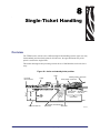
8 • Single-Ticket Handling . . . . . . . . . . . . . . . . . . . . . . . . . . . . . . . . . . . . . . . . . . 71
Overview . . . . . . . . . . . . . . . . . . . . . . . . . . . . . . . . . . . . . . . . . . . . . . . . . . . . . . . . . . . . .
Previously Encoded Tickets . . . . . . . . . . . . . . . . . . . . . . . . . . . . . . . . . . . . . . . . . . . .
Inserting a Single Ticket . . . . . . . . . . . . . . . . . . . . . . . . . . . . . . . . . . . . . . . . . . . . . . . . . .
Read and Decode . . . . . . . . . . . . . . . . . . . . . . . . . . . . . . . . . . . . . . . . . . . . . . . . . . . . . .
Encode and Print . . . . . . . . . . . . . . . . . . . . . . . . . . . . . . . . . . . . . . . . . . . . . . . . . . . . . . .
Ejecting the Ticket . . . . . . . . . . . . . . . . . . . . . . . . . . . . . . . . . . . . . . . . . . . . . . . . . . . . . .
71
72
72
73
73
74
9 • Error Handling . . . . . . . . . . . . . . . . . . . . . . . . . . . . . . . . . . . . . . . . . . . . . . . . . 75
Power Up . . . . . . . . . . . . . . . . . . . . . . . . . . . . . . . . . . . . . . . . . . . . . . . . . . . . . . . . . . . . 75
Normal Operation . . . . . . . . . . . . . . . . . . . . . . . . . . . . . . . . . . . . . . . . . . . . . . . . . . . . . . . 75
10 • Error Codes and Status Reporting . . . . . . . . . . . . . . . . . . . . . . . . . . . . . . . . 77
Status . . . . . . . . . . . . . . . . . . . . . . . . . . . . . . . . . . . . . . . . . . . . . . . . . . . . . . . . . . . . . . . . 77
Security Additions . . . . . . . . . . . . . . . . . . . . . . . . . . . . . . . . . . . . . . . . . . . . . . . . . . . . . . 78
Errors . . . . . . . . . . . . . . . . . . . . . . . . . . . . . . . . . . . . . . . . . . . . . . . . . . . . . . . . . . . . . . . . 79
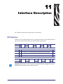
11 • Interface Description . . . . . . . . . . . . . . . . . . . . . . . . . . . . . . . . . . . . . . . . . . . 81
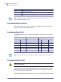
DIP Switches . . . . . . . . . . . . . . . . . . . . . . . . . . . . . . . . . . . . . . . . . . . . . . . . . . . . . . . . . .
Communications Protocol . . . . . . . . . . . . . . . . . . . . . . . . . . . . . . . . . . . . . . . . . . . . . . . .
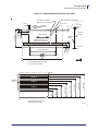
Communications Port . . . . . . . . . . . . . . . . . . . . . . . . . . . . . . . . . . . . . . . . . . . . . . . . . . . .
Communications Cable . . . . . . . . . . . . . . . . . . . . . . . . . . . . . . . . . . . . . . . . . . . . . . . . . .
81
82
82
82
12 • Document Stock . . . . . . . . . . . . . . . . . . . . . . . . . . . . . . . . . . . . . . . . . . . . . . 83
Ticket Base Material . . . . . . . . . . . . . . . . . . . . . . . . . . . . . . . . . . . . . . . . . . . . . . . . . . . . .
Coating and Preprint . . . . . . . . . . . . . . . . . . . . . . . . . . . . . . . . . . . . . . . . . . . . . . . . . . . .
Thermal-Print to Preprint Alignment . . . . . . . . . . . . . . . . . . . . . . . . . . . . . . . . . . . . .
Magnetic Media . . . . . . . . . . . . . . . . . . . . . . . . . . . . . . . . . . . . . . . . . . . . . . . . . . . . . . . .
Ticket Dimensions and Perforation . . . . . . . . . . . . . . . . . . . . . . . . . . . . . . . . . . . . . . . . .
Tickets With 45° Cut Corners . . . . . . . . . . . . . . . . . . . . . . . . . . . . . . . . . . . . . . . . . . .
84
85
85
85
86
89
13 • Firmware History . . . . . . . . . . . . . . . . . . . . . . . . . . . . . . . . . . . . . . . . . . . . . . 91
Index . . . . . . . . . . . . . . . . . . . . . . . . . . . . . . . . . . . . . . . . . . . . . . . . . . . . . . . . . . . . 95
03/05/2009
TTPM2™ Installation and Programming Manual
P1003645-001
5
6
Contents
P1003645-001
TTPM2™ Installation and Programming Manual
03/05/2009
1
Introduction
This document describes installation and operation of TTPM2 Ticket Printer/Encoder, which
creates credit-card-wide documents with magnetic encoding and thermal printing.
Document Printing
TTPM2 uses the direct thermal printing technique and can print the entire thermo sensitive
surface of the document with text or graphics, or both. Text block position and orientation is
software programmable as is the character size.
A text block can be identified as either fixed information which is stored in the unit until an
”All Clear” software command is sent, or as variable information, automatically erased as
soon as printing of the document has been completed. This feature allows printing from a data
file containing the variable data information.
EAN-13, Code 39, and Code 2-of-5 interleaved bar-codes can be generated and printed.
Magnetic Encoding
Two magnetic tracks can be encoded: Either with standard low coercivity recording, or
optional “household-magnet proof” high coercivity recording.
Track Combinations
• ISO track 2 at 75 BPI (Bits Per Inch), and ISO track 3 at 210 BPI
• ISO track 1 at 210 BPI, and ISO track 2 at 75 BPI
• Center track at 75 or 210 BPI
Naturally, the TTPM2 can be used for encoding on a single track only.
Encoding in ISO standard format, or in hexadecimal format, is software selectable. Read-afterwrite is automatically performed. Software selectable decode functions are available.
03/05/2009
TTPM2™ Installation and Programming Manual
P1003645-001
8
Introduction
Document Handling
Document Handling
A standard TTPM2 printer has one document entry for fanfold ticket stock, and one entry for
handfed tickets. The printer can be ordered in Dual Consecutive enTry (DCT) version with
both upper and lower entries designed for fanfold ticket stock.
There are three optional front load alternatives designated FL1, FL2, and FL3. FL1 and FL2
make it possible to load single tickets through the ticket exit, which replaces the upper single
ticket entry at the rear of the printer. In addition to this, FL2 and FL3 have a wastebasket
function for redirecting used or invalid tickets to a wastebasket, thus preventing useless tickets
being presented to the customer.
FL3 makes it possible to fully eject the ticket so that it falls into a tray where the customer
picks it up, or to a wastebasket as described above.
An external card dispenser that can be added to the printer handles sheet cut tickets and cards.
The card dispenser can hold a 95mm ticket pile (200 to 400 tickets depending on ticket
thickness).
P1003645-001
TTPM2™ Installation and Programming Manual
03/05/2009
2
Installation
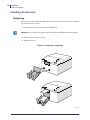
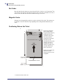
The TTPM2 comes as desktop printer with a cover and a built-in power supply and, or as an
OEM printer mechanism for kiosk applications.
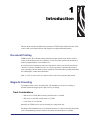
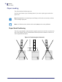
Figure 1 • Front view, desktop printer, and OEM printer mechanism
P u sh b utton s an d in dic a tors
D o cu m en t e xit
O ptio na l fron t loa d m ec ha nism
S W 95 06 5 C
03/05/2009
TTPM2™ Installation and Programming Manual
P1003645-001
10
Installation
Installing a Desktop Printer
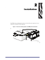
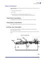
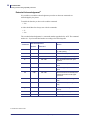
Figure 2 • Rear view, desktop printer, and OEM printer mechanism
Upper document entry
Power ON/OFF
switch
Power
cable
receptacle
Lower
document entry
Power connector
Fuse
holder
RS 232 interface connector
SW95065D
Installing a Desktop Printer
1. Verify that the supply voltage range stated on the type plate is suitable for your local line
voltage.
2. Connect the printer to a line outlet with safety ground.
The ground potential should be the same as for the host computer. If ground potentials
differ, use a short distance modem between the computer and the printer.
3. Clear the memory of the printer by making a general reset (hold down all three buttons
while turning ON the printer, then turning it OFF again).
4. Turn on the printer.
The green indicator should light up.
5. Press the front button.
The green indicator starts flashing and the yellow indicator lights up, indicating ”Out of
Paper”.
6. Turn the tickets so that the magnetic stripe is on the left side facing downwards, as seen
from the front of the printer.
7. Insert tickets in the lower document entry. The printer feeds the tickets forward and cuts
and ejects one ticket.
8. Turn off the host computer and the printer.
9. Connect a serial cable between the COM port of the host computer and the serial input of
the TTPM2 printer.
The printer is ready for use.
P1003645-001
TTPM2™ Installation and Programming Manual
03/05/2009
Installation
Installing an OEM Printer Mechanism
Figure 3 • RS232 serial interface connector pin assignment
Pin 6
Pin 1
SW97101C
Installing an OEM Printer Mechanism
The TTPM2 OEM printer mechanism should be installed in some kind of enclosure such as a
self-service kiosk.
Preventing ESD and earth currents from affecting the printer operation requires proper
connection of the printer chassis to protective earth through a mounting platform or through a
separate earth conductor.
Trouble free printer operation also requires the printer’s optical sensors to be shielded from
ambient light.
Additional space is required for paper stocking and paper jam. Consider mounting the printer
on a movable platform so that the printer can be maintained outside the printer enclosure.
03/05/2009
TTPM2™ Installation and Programming Manual
P1003645-001
11
12
Installation
Installing an OEM Printer Mechanism
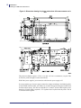
Figure 4 • Dimension drawing for printer mechanism. All measurements are in
mm
The printer mechanism requires +5 Vdc, 0.3 A, and + 24 Vdc 2 A continuous, 6 A peak. This
is fed to the printer through J5 on the control board.
With Zebra power supplies, just connect the cable from the power supply to J5.
If you use another type of power supply, connect the voltages according to the following table.
At the TTPM2 end of the cable, use a Molex 22-01-2065 connector housing and six Molex 0850-0032 contact springs. The cable area should be 6 x 0.24mm2, and the cable length no more
than 0.5 m. If longer cable is required, a 5 V regulator has to be placed near the printer. The 24
V should feed this regulator.
P1003645-001
TTPM2™ Installation and Programming Manual
03/05/2009
Installation
Installing an OEM Printer Mechanism
Figure 5 • Power supply connector pin assignment
Note • Both the 5 V and 24 V ground, as well as the chassis of the printer, must be connected
to ground potential (safety ground).
Caution • If you do not use a non Zebra Power supply, the one you use must have the
correct timing; 5 V must be on and stable in advance of 24 V at power on, and remain on
until after 24 V disappears at power off.
After fastening the printer, proceed with Introduction on page 7.
03/05/2009
TTPM2™ Installation and Programming Manual
P1003645-001
13
14
Installation
Installing Accessories
Installing Accessories
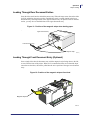
Output tray
The output tray collects the printed and coded tickets in a neat stack. Use the tray if you intend
to print many tickets at a time.
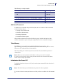
1. Loosen the two screws at the front of the TTPM2 case.
Important • Never loosen more than 5 turns or the nut plate will fall down inside the printer!
2. Hook the tray on to the two screws.
3. Tighten the screws.
Figure 6 • Installing the output tray
SW 97105 R1
P1003645-001
TTPM2™ Installation and Programming Manual
03/05/2009
Installation
Installing Accessories
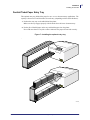
Fanfold Ticket Paper Entry Tray
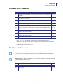
This optional entry tray holds ticket paper for one- or two- document-entry applications. The
capacity is between 125 and 300 tickets for each entry (depending on ticket stock thickness).
1. Position the entry tray on the table behind the printer.
Make sure the tray engages properly with the hook above the lower document entry.
2. Put the pile of fanfold paper on the tray and load the paper into the printer.
Never add more than a 5-cm pile at a time. Otherwise the paper will not feed correctly.
Figure 7 • Installing the optional entry tray
SW97106
03/05/2009
TTPM2™ Installation and Programming Manual
P1003645-001
15
16
Installation
Installing Accessories
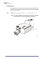
Card Dispenser
The TTPM2 model with card dispenser is fully assembled by Zebra. Both the TTPM2 and the
card dispenser are mounted on a common base plate (not shown). The dispenser is connected
to the TTPM2 control board and the serial interface is moved to the back of the card dispenser
by means of an extension cable.
Example • Follow the procedure Introduction on page 7, and Introduction on page 7.
Figure 8 • A desktop TTPM2 printer equipped with card dispenser. The OEM
printer mechanism can also be equipped with card dispenser.
C ard dispe nser
S W 9 7 11 8 B
P1003645-001
TTPM2™ Installation and Programming Manual
03/05/2009
3
Operation
Operator Controls
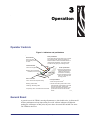
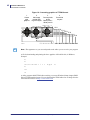
Figure 9 • Indicators and pushbuttons
Red indicator
Error, turn OFF
and ON the printer
to clear.
Rear pushbutton
Press and hold at power ON to turn on paper
jam clearing mode. Press front button to
advance ticket forward and middle button to
retract ticket backwards. Turn printer OFF
and ON to exit paper jam clearing mode.
Yellow Indicator
Center pushbutton
Fixed: Out of paper.2
Blinking: Print command
received, but out of paper.
Green indicator
Fixed: Power ON & printer ready.
1. Ejects any document in
the selected ticket track.
(Same as when an !E
command is received.)
2. Press and hold at power
ON to run cleaning card
through printer.
Front pushbutton
1
1.Cuts and ejects a ticket .
Blinking: Insert ticket.
2. Press and hold at power ON to enter
self test mode. Press again to encode
and print one ticket. The printout
shows current firmware version. Turn
Temporarily OFF: Commands are executed.
printer OFF and ON to exit self test
SW97108
mode.
Flickering: Receiving data.
General Reset
A general reset of the TTPM2, restoring all parameters to their default value, is effectuated if
all three pushbuttons are kept depressed at power ON. All three indicators will light but
nothing else will happen. At this point, the power has to be turned OFF and ON once more.
The TTPM2 is then reset.
03/05/2009
TTPM2™ Installation and Programming Manual
P1003645-001
Operation
Paper Loading
Paper Loading
The yellow indicator indicates paper out.
Press the center button to eject remaining tickets if you want to replace paper stock before
paper is out.
Note • Do not hold the front button depressed! Doing so will result in erroneously cut tickets
often resulting in paper jam.
Note • On CD 200 versions, load new ticket stock, then press the center pushbutton.
Paper Stock Positioning
The ticket stock should be oriented with the magnetic stripe down to the left as seen from the
front of the TTPM2. The pile of fanfold tickets should be placed at a distance of at least one
ticket length behind the printer.
Figure 10 • Positioning the ticket stock
> One ticket length
18
90°
SW97116
P1003645-001
TTPM2™ Installation and Programming Manual
03/05/2009
Operation
Paper Loading
Loading Through Rear Document Entries
Insert the ticket stock into the desired document entry. When the input sensor detects the ticket
it will be pulled into the active position. Fanfold ticket stock is usually loaded in the lower
document entry, and single tickets in the upper document entry. On printers with two fanfold
entries, you may also use fanfold tickets in the upper document entry.
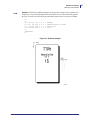
Figure 11 • Position of the magnetic stripe when loading paper
Upper document entry
Lower document entry
Magnetic stripe
SW97113
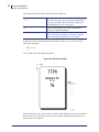
Loading Through Front Document Entry (Optional)
Insert a single ticket into the document entry with the magnetic stripe facing down to the left,
as seen from the front of the printer. When an !L3 command has been received and the input
sensor detects the ticket, this will be pulled into the active position of the upper rear document
entry.
Figure 12 • Position of the magnetic stripe at front load
Magnetic stripe
SW97114
03/05/2009
TTPM2™ Installation and Programming Manual
P1003645-001
19
20
Operation
Paper Loading
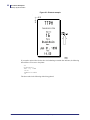
Loading Sheet-cut Tickets In Optional Card Dispenser
The card dispenser is factory adjusted to a specific card thickness, usually 0.18 mm to
0.25 mm as indicated on a label on the dispenser. Using thicker or thinner tickets will cause
paper jam.
The ticket stock should be oriented with the magnetic stripe down to the left as seen from the
front of the TTPM2. Put the paperweight on top of the ticket pile, then press the center push
button to load a ticket and the printer is ready.
Figure 13 • Loading tickets in the card dispenser.
P ape r w e igh t
Tickets
M agnetic stripe
C ard dispenser
S W 9 7 11 8 -R 2
P1003645-001
TTPM2™ Installation and Programming Manual
03/05/2009
Operation
Paper Jam Removal
Paper Jam Removal
Open the TTPM2 cover to locate and remove the ticket that is stuck in the mechanism. Use the
following procedure:
1. Select paper jam clearing mode
2. Power OFF.
3. Push and hold the rear pushbutton while turning ON the power.
The red indicator shows a steady light to indicate paper jam clearing mode.
Tickets Stuck In Input Module
Press and hold the center push button to eject the ticket towards the rear of the unit.
Tickets Stuck In Output Module
Press and hold the front push button to eject the ticket towards the front of the unit.
Exit Paper Jam Clearing Mode
Power OFF and back ON again, the TTPM2 is operational but any ticket information
previously sent to the unit is lost.
You can also power OFF the printer and turn the feed rolls manually to remove the blocking
ticket.
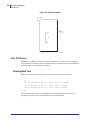
Figure 14 • Paper path.
03/05/2009
TTPM2™ Installation and Programming Manual
P1003645-001
21
22
Operation
Self Test Mode/Ticket Repeat Mode
Self Test Mode/Ticket Repeat Mode
Self Test
1. Press and hold the front pushbutton at power ON to enter self-test mode.
2. Press again to encode and print one ticket. The printout shows current firmware version.
3. Turn printer OFF and ON to exit self-test mode.
Repeat Fixed Print
1. Start self-test mode as described above.
2. Download the ticket data to the printer, and print one ticket.
The data must only contain fixed text, fixed encoding data, and graphics.
3. Press the front button once and an exact copy of the first ticket will be printed.
This will be repeated each time that the front button is pressed.
4. Turn printer OFF and ON to return to normal operation.
Note • Do not hold the front button depressed! Doing so will result in erroneously cut tickets
often resulting in paper jam.
Note • Repeating fixed print only works on printers where the auto clear function is OFF.
Auto clear is enabled/disabled with a DIP-switch on the control board.
P1003645-001
TTPM2™ Installation and Programming Manual
03/05/2009
4
Command Set
The command set is designed in accordance with industry standards and is enhanced with
functions unique to this product. The command language uses only printable ASCII characters
for easy adaptation to any host system.
03/05/2009
TTPM2™ Installation and Programming Manual
P1003645-001
24
Command Set
Syntax
Syntax
A command string always starts with an exclamation mark (ASCII 33 or HEX 21) serving as
command identifier. The exclamation mark must be at the first position of the line, that is,
directly after a CR LF. Otherwise it will not be recognizes as command identifier.
The characters immediately following the “!” (21H) form the actual command to the printer.
The command consists of 1–3 characters and is followed, when applicable, by a sub command,
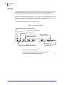
formatting commands, and data separated by space characters as shown in Figure 15.
A Carriage Return and Line Feed end each command.
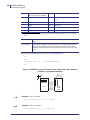
Figure 15 • Command Syntax
Command identifier
Command (1 to 3 characters)
Sub command
1
Formatting commands1
separated by spaces
Space character
(ASCII 32 or HEX 20)
P1003645-001
1
Data enclosed in
quotation marks2
New line = CR LF
(ASCII 13 10
or HEX 0D 0A)
1
Only used with some commands
2
Graphical data starts directly without any quotation mark
and ends after the specified number of bytes
TTPM2™ Installation and Programming Manual
SW97119
03/05/2009
Command Set
Printing and Encoding Capability Overview
Printing and Encoding Capability Overview
Text
It is possible to print text in four fonts, in four
orientations, and in 16 different sizes.
Text is divided into two categories:
•Fixed text that is repeated on following tickets
•Variable text that is deleted immediately after printing
Fixed text is normally used for headers etc. as well as
for establishing printing parameters for the variable
information.
Variable text is used for names, seating numbers,
departure times, dates, etc.
p
Graphics
Bitmap graphics, such as logotypes, prints in the size and orientation in which they where
downloaded. Graphics print on all following tickets until a ”Clear all” command is received,
so you only have to download graphics once.
Remember, when creating graphics for the TTPM2 printer, that the pixels are not square, but
has a height/width ratio of 1.32:1.
03/05/2009
TTPM2™ Installation and Programming Manual
P1003645-001
25
26
Command Set
Printing and Encoding Capability Overview
Bar Codes
Bar code data fed to the printer are converted to an EAN13, Code39, or 2-of-5 interleaved1 bar
code. The bar code prints on all subsequent tickets until a ”Clear all” command is received, or
until new bar code data with the same coordinates and type is received.
Magnetic Codes
Messages can be magnetically encoded on a stripe at the back of the ticket. The message can
be between 37 and 107 characters long depending on the coding standard and density you
select.
Positioning Data on the Ticket
X1
X384
Y1
Frame
North orientation at X=1, Y=1
East oriented text at X=384, Y=1
FEED
DIRECTION
Items to be printed are
placed within frames.
You position the frame by
defining the X and Y
coordinate of the upper
left corner, and the
orientation of the frame.
The frame is then
automatically sized to the
contents you put in it
(character size, No. of
characters, graphics size,
and other data for the
item to be printed).
Frames can overlap each
other. You can for
instance print text on top
of graphics.
86 mm:Y500
(Y700 in high res mode)
Printable width 51.07mm
110 mm: Y650
(Y900 in high res mode)
SW95026A
1. Included from firmware version 3.65.
P1003645-001
TTPM2™ Installation and Programming Manual
03/05/2009
Command Set
Printing and Encoding Capability Overview
Triggering a Printout
Putting text, graphics, bar and magnetic codes on the ticket as described above only builds an
image of the ticket in the printer memory. To actually print something on a ticket, you must
send a print command:
• !P↵
Every received ”!P CR LF” prints one ticket. (On dual document entry printers you must also
send a select document entry command, see Document Entry Commands on page 31.)
If you have variable text on your tickets, the data to be printed in the variables must precede
the !P. If two variables are used for instance, a print command could look like this:
Example •
Thursday 16 October 1999 ↵
Seat 311 ↵
!P ↵
Command Acknowledgment
Ticket issuing is automatically acknowledged by the TTPM2 by sending an ACK (06h) to the
host computer after a successful read-after-write of the encoded magnetic information.
If no encoding command and data are sent to the TTPM2, the ACK is still sent (read-afterwrite verifies that no data is encoded).
Some other commands are also acknowledged, see table below.
Note • ACK/NAK must be enabled through dipswitch settings, see DIP Switches
on page 81.
03/05/2009
TTPM2™ Installation and Programming Manual
P1003645-001
27
28
Command Set
Printing and Encoding Capability Overview
Extended Acknowledgement2
It is possible to extend the acknowledgement procedure so that most commands are
acknowledged by the printer.
To enable the function you have to the send the command:
• !CA
A ticket should therefore always start with the commands:
• !C
• !CA
The extended acknowledgement is a command number appended to the ACK. The command
number is a 1 byte hexadecimal number according to the following table.
Command
!P
Acknowledgement
Normal
06h
Extended
When?
06h 80h 06h 02h
After a successful magnetic encoding. After printing.
!C
06h 04h
After clear memory
!F
06h 05h
After formatting data in memory
!L
06h 08h
After successful track load / eject
operation
!L17
06h
06h 08h
When the lower input contains ticket
stock
!L18
06h
06h 08h
When the upper input contains ticket
stock
!L3
06h
06h 08h
When a ticket has successfully been
loaded from the front to the upper
input track.
!L4
06h
06h 08h
When successful eject through front
entry
!E
06h 09h
After successful eject through rear
entry
!Q
06h 14h
After transaction string is written in
memory
!Z
06h 18h
After burn time is changed
!X
06h 19h
After changed resolution
2. Introduced in version 4.06.
P1003645-001
TTPM2™ Installation and Programming Manual
03/05/2009
Command Set
Printing and Encoding Capability Overview
The following is a simple example:
Sent to printer
Acknowledgement
!C
06h 04h
!CA
06h 04h
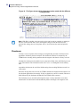
!F T E 309 014 10 03 02 1 "TEST TICKET WITH FULL"
06h 05h
!F T E 259 024 10 03 02 1 "75 BPI TRACK 2 STRING"
06h 05h
!M1234567890123456789012345678901234567
06h 80h
!P
06h 02h
Additional Commands
In addition to the command that specifies the print, there are a number of other commands
used for functions such as:
• Clearing of the TTPM2 buffer
• Selection of document entry
• Decoding of documents
• Generation of status requests
All applicable commands are listed in the following pages. Detailed descriptions of the
software commands are given with syntax explanations as well as commented examples.
Ticket Memory
The TTPM2 printer has 128k of nonvolatile RAM (lithium battery backup, with
approximately 7 years battery life). This memory stores the entire ticket so you can continue
after power OFF, without having to reload the data.
The ticket printing area is 384x512 pixels for an 86 mm ticket, and 384x656 pixels for a
110mm ticket.
Note • Make sure not to print data outside this area when you use the !F command.
If you do, you write in parts of the memory that are used for other functions in the printer,
and the result is totally unpredictable.
Initialization After Power OFF
To initialize the printer after power ON you just send a print command (!P) and the printer is
ready for use.
Note • The first !P after power ON initializes the printer. No ticket is produced.
If you want to clear the memory and start a new ticket you have to send the clear all command
!C.
03/05/2009
TTPM2™ Installation and Programming Manual
P1003645-001
29
30
Command Set
Summary of Commands
Summary of Commands
System Commands
!C
Clear all
!C1
Clear retract counter
!CA
page 33
page 33
a
Clear all and enable extended acknowledgement
b
page 33
!F A
Feed- acceleration and speed
page 38
!P
Encode and print document
page 33
!P@
Encode and print document, and eject it in wastebasket (FL2 and FL3
printers)
!PE
Encode and print document, and eject it to tray (for FL3 printers)c
!PS
Print slowd
!PM
Print mediumd
!PF
Print fastd
!U
Firmware version querye
!S
Status request
page 35
ENQ
Status request immediate
page 38
CAN
General reset, equivalent to power OFF/ON (takes 20 s to execute)
!Q
Writes a transaction string to RAM
!V
page 34
Reads the transaction string written by !Q
e
e
page 35
!W
Reads thermal print progress indicator
page 36
!X
Set resolution
page 36
f
!Y
!Y1
!Z
page 36
Read ticket counter
g
Read retract counter
page 36
h
page 37
Burn time
a. Introduced in firmware 01789-406
b. Introduced in firmware version 4.49d
c. Introduced in firmware xxxxx-399s, replaced by !F A in version 4.49
d. Introduced in firmware xxxxx-3.39zb
e. Introduced in firmware xxxxx-332
f. Introduced in firmware xxxxx-360
g. Introduced in firmware xxxxx-424
h. Introduced in firmware xxxxx-384
P1003645-001
TTPM2™ Installation and Programming Manual
03/05/2009
Command Set
Summary of Commands
Document Entry Commands
!A
Sets ticket length for roll ticket without blackmarksa
page 40
!E
Ejects document through the upper rear document entry (for example after
decoding)
page 40
!L1
Selects lower rear document entry, and waits if paper is out (for units with
dual consecutive entriesb)
page 40
!L2
Selects upper rear document entry, and waits if paper is out (for units with
dual consecutive entries)
page 40
!L3
Loads document through front entry
page 41
!L4
Ejects document through front entry
page 41
!L5
Transports document to waste bin (only for printers with front load 2 and
3)
page 41
!L17
Selects lower rear document entry and signals if paper is out (for units
with dual consecutive entriesc)
page 42
!L18
Selects upper rear document entry and signals if paper is out (for units
with dual consecutive entriesc)
page 42
!T
Sets timeout for retract functiond
page 42
a. Introduced in firmware version 4.55.
b. !L1, !L2, !L17 or !L18 must be selected on units with dual document entries.
c. Both the 5 V and 24 V ground, as well as the chassis of the printer, must be connected to
ground potential (safety ground).
d. Introduced in firmware version 3.75.
Print-Parameter Commands
Note • Make sure not to print data outside this area when you use the !F command.
If you do, you write in parts of the memory that are used for other functions in the printer,
and the result is totally unpredictable.
Note • Both the 5 V and 24 V ground, as well as the chassis of the printer, must be connected
to ground potential (safety ground).
03/05/2009
!F T
Print text
page 43
!F G
Print graphics
page 45
!F C
Print bar code
page 47
!F M
Specifies No. of retries + cancellation text to be printed if encoding fails
page 49
TTPM2™ Installation and Programming Manual
P1003645-001
31
32
Command Set
Summary of Commands
Magnetic Encoding/Decoding Commands
!D
Reads and decodes data in ISO format from track 2 (or center track)
page 53
!D1
Reads and decodes data in ISO format from track 1
page 53
!D3
Reads and decodes data in ISO format from track 3
page 53
!I
Defines data to be encoded in ISO format on track 3
page 51
!J
Defines data to be encoded in ISO format on track 1
page 51
!K
Defines data to be encoded in Hex format on track 1 or 3 (as applicable)
page 51
!M
Defines data to be encoded in ISO format on track 2 (or center track)
page 51
!N
Defines data to be encoded in hexadecimal format on track 2 (or center
track)
page 51
!N+
Same as !N but reverses the bit order a)
!O1
Reads data in hexadecimal format from track 1 (or center track)
page 7
!O2
Reads data in hexadecimal format from track 2 (or center track)
page 7
!O3
Reads data in hexadecimal format from track 3 (or center track)
page 7
a. Added in firmware version xxxxx-332.
P1003645-001
TTPM2™ Installation and Programming Manual
03/05/2009
5
Command Reference
System Related Commands
!C
Clear all
This command takes no parameter. All definitions are cleared. Stored layout is erased.
Subsequent !C’s are ignored.
The !C command is also used to initialize TTPM2 after a power ON. If existing print layout
shall be saved, !P shall be used for printer initialization. See TTPM2 Start-Up on page 59.
If no fixed data is used on the tickets, Autoclear can be used to clear the memory between
tickets instead of using !C. Autoclear executes faster than !C. When autoclear is enabled any
!C commands in the received data will be ignored, apart from when initiating the printer.
Setting DIP-switch 4 to ON enables Autoclear.
• !CA, adding an A to the !C command enables extended acknowledgement.
• !C1, adding the digit 1 to the !C command clears the wastebasket counter. See !Y1.
!P
Print
This command effects both the encoding, printing, cutting and ejecting of a ticket.
Printing follows a successful encoding. The magnetic code and print information, as well as
cut and eject behavior, must first be defined using the applicable commands.
The Print command can also be used to initialize the TTPM2 after power OFF (as an
alternative to !C) in order to save any ticket layout stored in the TTPM2. See Additional
Commands on page 29 and TTPM2 Start-Up on page 59.
If !P is received and the printer is out of paper, it will give error code NAK P and discard the
received data.3
3. Introduced in firmware in version 4.13
03/05/2009
TTPM2™ Installation and Programming Manual
P1003645-001
34
Command Reference
System Related Commands
Encoding Retries
Adding a single digit after the !P makes it possible to set the maximum number of encoding
retries for one ticket. The number given is the number of additional tries i.e. !P 1 means one
normal attempt plus one retry. Default is 1, which is the value used if no digit is present.
Eject to Waste Basket
Adding an @ character (!P@) makes the printer eject the completed ticket into wastebasket
(for FL2 and FL3 printers). One use for this can be to make status printouts that are not
intended for the customer.
Eject Fully
Adding an E (!PE) makes the printer eject the ticket fully so that it can fall down into a tray
(for FL3 printers)4
Digits and @, or digits and E can be mixed on the same line, for example !P5@ makes five
encoding retries, and ejects the ticket into the wastebasket.
Set Print Speed
Adding letters S, M, or F adjust the print speed:5
!PS
Print slow
!PM
Print medium
!PF
Print fast.
Print quality is very much dependent on speed. The normal print speed is used unless you
select Fast or Slow with this command.
!Q
Write transaction string
!Q writes a string with up to 15 ASCII characters to a buffer memory in the printer.
Example: !Q asdfgh <CR><LF>
After the ticket has been correctly encoded/printed, the string is copied to a buffer in the
battery backed up RAM. This buffer can be read by the !V-command.
The transaction string is committed at the precise point where a useable ticket has been
produced. The only way to reset a transaction string is to successfully print another useable
ticket that was initiated with !Q. Loss of power or a reset or any other instruction leaves the
string intact.
4. Added in firmware version xxxxx-399s
5. Added in 3.39zb
P1003645-001
TTPM2™ Installation and Programming Manual
03/05/2009
Command Reference
System Related Commands
!S
Status request
The TTPM2 responds by sending two bytes to the host computer. Byte 1 indicates the status of
the various TTPM2 sensors according to the following table. Byte 2 reports the temperature of
the thermal print head and is only used internally in the TTPM2.
Bit
Function
Sensor
Value “1”
Value “0”
0
Lower rear document entry
J6
Paper present
No paper
1
Upper rear document entry
J7
Paper present
No paper
2
Top-of-form
J8
Paper present
No paper
3
Cutter position
J9
Paper present
No paper
4
After cutter position
J10
Paper present
No paper
5
Cutter
J21
Cutter home
Cutter not homea
6
Print head
–
OK
Error
7
Front Load Sensor
J11
Paper present
No paper
a. On CD200 versions with “card level low” sensor, this bit indicates low card level. (printer version 02441-002, 5600-A0015)
See also: ENQ
!SD
Status request, DIP-switch settings
The TTPM2 responds with one byte containing 1 bit for each switch. 1 = on, 0 = off.
Bit
7
6
5
4
3
2
1
0
Dip switch No:
8
7
6
5
4
3
2
1
!U
Firmware version querya
a. Introduced in firmware version 3.2
The TTPM2 responds by sending the following string:
00906_320 TTPM2 Ticket Printer/Encoder
Where 00906 is the firmware number for the TTPM2 standard, and 320 is the firmware
revision, in this case 3.20.
!V
Read transaction stringa
a. Introduced in firmware version 3.32
Reads the string stored by !Q from the memory in the printer.
03/05/2009
TTPM2™ Installation and Programming Manual
P1003645-001
35
36
Command Reference
System Related Commands
Read thermal print progress indicatora
!W
a. Introduced in firmware version 3.32
Reads a value indicating the number of bytes actually printed on the ticket (both blank and non
blank). The number consists of 4 hexadecimal digits and should normally be equal to 5BE0. A
lower number together with the absence of the 03H indicates that the last ticket was not fully
printed and a decision may be taken whether the system should reissue the ticket or alert the
supervisor.
This is a safety feature to minimize the risk of valid tickets being duplicated without attention
from the system, by turning off the power at a certain point.
!X
Set resolution
Sets the resolution of the print. This only affects the resolution in the transport direction of the
ticket. 0=normal resolution, (5.7dots/mm). 1=high resolution (8.5 dots/mm).
Read ticket countera
!Y
a. Introduced in firmware version 3.60
Reads out the internal ticket counter from the control board. This counter starts from 0 when
the printer is new and is incremented by one fore each completed !P sequence.
The result is sent as 12 decimal digits + CR + LF
!Y1
Read retract countera
a. Introduced in firmware version 4.24
Reads out the internal retract counter. This counter is incremented by one for each ticket that is
retracted and thrown in the wastebasket.
To reset the counter to zero, send the command:
C1
The result is sent as 12 decimal digits + CR + LF
Note • Retract function is only available on printers with FL2 and FL3.
P1003645-001
TTPM2™ Installation and Programming Manual
03/05/2009
Command Reference
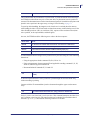
System Related Commands
Burn timea
!Z
a. Introduced in firmware version 3.84
Setting
Burn time
Print density
16
512
μs
Test
17
544
μs
Test
18
576
μs
Test
19
608
μs
Test
20
640
μs
Test
21
672
μs
Test
22
704
μs
Test
23
736
μs
Test
24
768
μs
Test
25
800
μs
Test
26
832
μs
Test
27
864
μs
Test
28
896
μs
Test
29
928
μs
Test
30
960
μs
Test
31
992
μs
Test
Lightest print
Default
Darkest print
The burn time controls the print density. It is used to set the heating so that it is adequate for
the thermal paper used as ticket material. Set it to the lowest burn time that gives acceptable
print quality.
Example • !Z 20 <CR><LF> sets burn time 640 μs
The burn time setting is stored in the non-volatile memory.
A three-button reset returns the setting to default value.
Caution • A longer burn time puts more load on the printhead, so do not use a longer burn
time than required for a clearly legible print. Settings over 27 are not recommended.
03/05/2009
TTPM2™ Installation and Programming Manual
P1003645-001
37
38
Command Reference
System Related Commands
ENQ
Status request, immediate
The TTPM2 responds by sending the same 1 byte response to the host computer as is sent as
byte 1 in response to the !S command. The ENQ command is effected immediately after
receipt, whereas the !S command is effected in sequence when received.
TTPM2 has two feed motors, one for encoding and one for printing.
!F A
Feed- acceleration and speeda
a. This command was introduced in firmware version 4.49d
This command sets the start-frequency and the top speed of each motor.
Note • This command should not be used! Suitable speed is selected by Zebra and set as
default parameters in the firmware. The speed setting has to reflect the motors fitted in the
printer and the mechanical buildup of the printer. A single unit may be tunable to a higher
speed but it is not certain that the settings work on the next printer.
Note • A three-button reset will set the values to factory default.
Syntax for defining and downloading graphics data is as follows:
P1003645-001
TTPM2™ Installation and Programming Manual
03/05/2009
Command Reference
System Related Commands
!F A N <start freq> <top speed> <motor> 1 1 1_”remark”
!F
Command to load print-parameter information.
A
Indicates acceleration and speed mode.
N
Print orientation. This is ignored in acceleration and speed mode.
Orientation is always North (N). The printer requires the N to be inserted.
<start freq>
Start frequency. Set the base frequency from where the acceleration starts. A
value of 30 indicates a start frequency of 300 Hz.
Top speed
Top speed is the frequency at which the acceleration stops. A value of 450
sets top speed to 4500 Hz.
motor
“1” selects encoding motor, while “2” selects print motor
1
Not used. Must be set to 1.
1
Not used. Must be set to 1.
1
Not used for graphics printing. Must be set to 1.
space
One space has to follow the "1" before the graphics data.
Remark
Here you can enter a remark describing the setting you just did. It will not be
printed.
Example •
!C<CR><LF>
!F A N 30 250 1 1 1 1 "Encode speed (full-step)"<CR><LF>
!F A N 30 190 2 1 1 1 "Print speed (half-step)"<CR><LF>
!P<CR><LF>
03/05/2009
TTPM2™ Installation and Programming Manual
P1003645-001
39
40
Command Reference
Document-Entry Related Commands
Document-Entry Related Commands
Set ticket length for roll papera
!A
a. This command was introduced in firmware version 4.55
This command sets the ticket length if paper without gaps or black marks is used. One step is
0.7mm.
!A 127
!A 0
sets up a credit car sized ticket length.
turns off the function and reverts to gapped ticket stock. This is the default
setting.
The mechanics of TTPM 2 works with ticket lengths between 54 and 120 mm.
!
E
Eject through rear document entry
This command ejects, through the rear document entry, any document positioned in the active
position for encoding (or after decoding). See Single-Ticket Handling on page 71 for the
definition of active/ standby ticket position.
!L1
Select lower rear document entry (dual entry printers only)
Selects lower rear document-entry and feed the leading document, in the consecutive supply
entry, to active position. If, in the preceding operation, the upper rear document entry has been
engaged, the document in that entry is retracted from the active position.
Note • On dual document entry printers, a ”select rear entry” command (!L1, !L2, !L17 or
!L18) must precede the print command (!P). An ACK character is returned if the command
was successful. If no paper is present, the yellow indicator lights up and the printer waits
until the operator insert new paper stock.
Note that DIP switch no. 6 must be set to ON to enable the ACK/NAK signaling.
See alternative command !L17.
!L2
Select upper rear document entry (dual entry printers only)
Same function as !L1, but selects upper rear document entry.
See alternative command !L18.
P1003645-001
TTPM2™ Installation and Programming Manual
03/05/2009
Command Reference
Document-Entry Related Commands
!L3
Load document from front entry (front load printers only)
This command lifts the print head for a specified time, to permit document insertion through
the TTPM2 front document entry/exit. At the same time, any document in active position is
retracted. The document inserted in the front document input/exit is loaded into the printer and
placed in active position in the upper entry, see Single-Ticket Handling on page 71.
To speed up ticket handling, the magnetic code of track two is read and placed in memory
when loading the ticket. !D will read track two data from memory without having to move the
ticket. Reading track one (!D1), or track three (!D3), requites a ticket read movement (from
active position, to the output module, and back again).
On error, the TTPM2 sends the following error codes to the host computer:
Error code
Error
NAK+B
No document is inserted within 60 seconds. Command !L3 is abandoned.
NAK+C
A document is inserted and immediately retracted.
NAK+D
A document is inserted, but the TTPM2 is blocked (paper jam)
NAK+E
Paper jam in the input feeder during an !L3 command.
A front loaded document resting in active position can be processed using one of the following
alternatives:
• Using the appropriate decode command !D, !D1, !D3 or !O.
• Using print parameter format command !F and applicable encoding command !I, !J, !K,
!M or !N, followed by print command !P.
• Document Related Commands !E, !L4 and !L5.
!L4
Eject document through front document entry (only already cut
ticket)
A document positioned in the active position is ejected through the front document entry,
without encoding or printing.
Compare with the !E command that ejects the document through the upper rear document
entry.
!L5
Eject document into waste bin (only printers w. waste bin)
Only for printers with front load 2 (with waste bin): This command transports the ticket from
active position to the waste bin. The same function can be obtained for cancelled tickets if
character ”@” or a “}” is inserted into the string of data to be encoded.
03/05/2009
TTPM2™ Installation and Programming Manual
P1003645-001
41
42
Command Reference
Document-Entry Related Commands
!L17
Select lower rear document entry and signal paper out (only dual
entry printers)
Same function as !L1, but when ticket loading fails the printer sends an error code (NAK + '1')
instead of waiting for paper to be loaded. It is then up to the system to determine if paper
should be loaded from the upper document entry instead.
!L18
Select upper, rear document entry and signal paper out (only dual
entry printers)
Same function as !L2, but when ticket loading fails the printer sends an error code (NAK + '1').
It is then up to the system to determine if paper should be loaded from the lower document
entry instead.
Sets timeout for retract function (only printers w. waste bina)
!T
a. Introduced in firmware version 3.75
!T@nn
nn is the delay in seconds
When a ticket is left in the output of the front load after the timeout nn has expired, NAK F is
sent to the host controller to indicate that the ticket hasn't been picked up.
If the customer takes the ticket before the timeout elapses, the printer sends a Bel (07H)
character.
@ Expands the signaling: If you have a Front load with waste basket function, the printer
retracts the uncollected ticket and ejects it into the wastebasket exit.
Note • The !T command should be sent after the !P (print) command. DIP-switch 6 must be
ON for status replies to be sent.
Example •
!P
!T @20
Retracts the ticket and sends NAK F if it has not been taken within 20 seconds
Example •
!P
!T 20
Sends NAK F if the ticket if it has not been taken within 20 seconds
Both examples above sends BEL if the ticket is taken
P1003645-001
TTPM2™ Installation and Programming Manual
03/05/2009
Command Reference
Print Related Commands
Print Related Commands
Introduction
!F is the general command for formatting the ticket print.
!F<type> <data>
The parameters are used as follows:
!F
Indicates that this is the start of a print field definition
<type>
Specifies the type of the field
T=
Text
G=
Graphics
M=
Ticket cancellation definitions (See Canceling a Ticket on page 49)
C=
Bar code
<data>
Depends on the type of field specified. See the following pages.
Text Printing
!F T
Format text for printing
Example •
!F T <orientation> <xpos> <ypos> 1 <height> <width> <font> <"text">
The parameters are used as follows:
!F
Indicates that this is the start of a print field definition
T
Indicates text mode
<orientation>
Specifies the way in which the text is to be oriented. This can be either
N(orth), E(ast), S(outh) or W(est). This terminology is described in
detail in the examples given in this document. Specific fonts may be
limited to one orientation only, see <font> below.
<xpos>
<ypos>
Specifies starting position for the text on the ticket. That is, the distance
in pixels from the upper left corner of the printable area to the upper lefthand pixel of the first character to be printed. Note that the resolution is
7.52 pixels/mm on the X-axis and 5.7 pixels/mm on the Y-axis in
normal, and 8.5 pixels/mm on the Y-axis for high resolution, see
command !X.
<fixed pitch>
No. of pixels from the start of one character to the start of the next.
Range 6 to 16. A value below 6 sets the default pitch. a
a. Introduced in firmware version 3.2
03/05/2009
TTPM2™ Installation and Programming Manual
P1003645-001
43
44
Command Reference
Print Related Commands
Note • Only used for font 1. Must be set to 1 for all other fonts.
<height> <width>
Specifies the height and width expansion of characters to be printed.
The height range is 1–16 times the default value. The width range is
1–16 for fonts 1 and 4, and 1–3 for fonts 2 and 3. See the font samples
in Printing and Encoding Capability Overview on page 25.
<font>
Selects the font (text appearance). Fonts 1, 2, 3, and 4 apply. Font 2
and 3 can only be North oriented. Fonts 1 and 4 can be set to any
orientation. Font 4 is a proportional character font. See the font
samples in Printing and Encoding Capability Overview on page 25.
Font appearance may differ from the font samples if you have custom
firmware in your printer.
<"text">
Text to be printed, or definition of a variable text field. Both plain text
and variable definitions have to be enclosed in quotes (" "). Variable
data to be printed as plain text is represented by "%V" in the format
data string. The information that should replace the variable are sent
before the !P print command at printout time. See Document
Examples on page 61.
Example • Example of a command for fixed text:
F T N 150 150 1 1 1 1 "Text"↵
Example • Example of a command for variable text:
F T N 150 150 1 1 1 1 "%V"↵
P1003645-001
TTPM2™ Installation and Programming Manual
03/05/2009
Command Reference
Print Related Commands
Graphics Printing
!F G
Format graphics for printing
TTPM2 can print bit map graphics. Graphic images are stored in the fixed memory area and
will therefore be repeated on every ticket until the next !C command is received.
Remember, when creating graphics for the TTPM2 printer, that the pixels are not square but
have a height/width ratio of 1.32:1.
Syntax for defining and downloading graphics data is as follows:
!F G <orientation> <xpos> <ypos> 1 <height> <width> 1_<Graphic_data>
03/05/2009
!F
Command to load print-parameter information.
G
Indicates graphics mode.
<orientation>
Print orientation. This is ignored in graphics mode. Orientation is always
North (N). The printer requires the N to be inserted.
xpos
Horizontal starting position in pixels for the upper left-hand corner of the
graphics block. Position will automatically be rounded off to be divisible
by 8 as a graphic block has to start at the first bit in a byte.
ypos
Vertical starting position in pixels for the upper left corner of the graphics
block.
1
Not used for graphics printing. Must be set to 1.
height
Height in pixel lines of the graphic block. The length of the ticket
determines maximum height. For an 86 mm ticket the maximum height is
approximately 500 pixel-lines.
width
Width in bytes of the graphic block. Maximum width is 48 bytes.
1
Not used for graphics printing. Must be set to 1.
space
One space has to follow the "1" before the graphics data.
Graphic_data
This is a block of bit mapped graphics data. The block is stored in the
printer starting at <xpos>, <ypos>. The numbers of bytes specified by
<width> are stored in one pixel line. The <ypos> is then incremented and
the next line is stored. This is repeated <height> number of times. It is up
to the user to send the correct number of bytes to the printer, that is,
<height> × <width>, as the printer will scan the input character stream for
the correct number of bytes.
TTPM2™ Installation and Programming Manual
P1003645-001
45
46
Command Reference
Print Related Commands
Figure 16 • Converting graphics to TTPM2 format.
1.
Create
pixel
graphics
2.
Add empty
vertical lines
to get full bytes
1 2 3 4 5 6 7 8
1
2
3
4
5
6
7
3.
Convert pixels
to bits
Black pixel=1
White pixel=0
12 8 32 8
64 16 4
0 0 0 1 0 0
0 0 1 1 1 0
0 1 1 1 1 1
1 1 1 1 1 1
0 1 1 1 1 1
0 0 1 1 1 0
0 0 0 1 0 0
2
0
0
0
1
0
0
0
4.
Covert bits
to bytes
1
0
0
0
0
0
0
0
10 H
38 H
7C H
FE H
7C H
38 H
10 H
1 byte
SW97123
!F G N 140 140 1 7 1 1 10H 38H 7CH FEH 7CH 38H 10H
Note • The appearance on your screen depends on the editor you use to write your program.
A file for downloading and printing the above graphics will look like this, in Windows
Notepad:
!C
!C
!F G N 140 140 1 7 1 1
8|þ|8
!C
!C
!L1
!P
A utility program called TTPM editor can help you convert Windows bitmap images (BMPfiles) to TTPM graphics format. You can download the TTPM editor free of charge from the
Zebra Internet web site at http://www.zebra.com.
P1003645-001
TTPM2™ Installation and Programming Manual
03/05/2009
Command Reference
Print Related Commands
Printing Bar Codes
!F C
Format bar code printing
Bar code printing can be used as ticket data carrier instead of, or in addition to, magnetic
encoding.
Note • To produce sharp code bars, the TTPM2 printer automatically reduces the print speed
by approx. 50% when printing tickets with east and west oriented bar codes. In firmware
version 3.50 and higher, this speed reduction is only valid for bar widths 1 and 2. Wider bar
codes are printed at full speed.
Bar code data is treated as fixed data. You can however replace a bar code by overlaying the
previous data with new bar code data on the same X- and Y-coordinates. This way you avoid
deleting the complete ticket with a reset (!C) when you want to update the bar code.
The syntax for defining and downloading of bar code data is as follows:
!F C <orientation> <xpos> <ypos> <bar 1> <height> <bar 2>
<type>_ <”bar code data”>
!F
Command to load print parameter information
C
Indicates bar code mode
<orientation>
Indicates print orientation. Can be north (N), east (E), south (S), or west
(W).
xpos
Starting position (pixel) for the upper, left-hand corner of the first code bar
in the string. Automatically rounded off to be divisible by 8, (first bit in a
byte).
ypos
Starting position (pixel) for the upper, left-hand corner of the first code bar
Bar 1
Width in pixels of both black and white bars, range 1–16. For EAN13 and
EAN/Code 128 the value must be set to 1. For Code 39 and Code 2-of-5
this sets the wide bars.
height
Code bar height
in pixels
Value
1=
16 pixels =
2.7 mm
2=
32 pixels =
5.3 mm
3=
48 pixels =
etc.
4=
64 pixels =
5=
80 pixels =
...
16 =
Bar 2
03/05/2009
256 pixels =
42.7 mm
Width in pixels of both black and white bars, range 1–16. For EAN13 and
EAN/Code 128 the wide/narrow ration is fixed and this sets the width of
the entire code. For Code 39 and Code 2-of-5 this sets the narrow bars.
TTPM2™ Installation and Programming Manual
P1003645-001
47
48
Command Reference
Print Related Commands
type
selects type of bar code. The
following types are available:
Value
1=
EAN13 (partly implemented, no check
sum)
Value
2=
Code 2-of-5 interleaved
Value
8=
EAN 128a
Value
9=
Code 128
Value
11 =
Code 39
a. Code 128 and EAN 128 are only implemented in firmware 00970-xxx, and it replaces
font 2.
space
A space (blank) has to be inserted between the type parameter and the data
string.
bar code data
This is a block of data to be converted by the TTPM2 and printed in bar
code form in accordance with the parameters identified. For available
characters and data string formats, please refer to the specific type of bar
code.
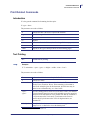
The following command string produces the ticket illustrated below:
!C
!L1
!F C N 12 102 1 4 3 1 "1234567890128"
!P
Figure 17 • EAN13 bar code. Use east or west oriented bar codes wherever
possible, to guarantee readability.
X
If dots are missing
the bar code will
still be readable
Y
FAST
Feed
direction
SLOWER
but more
reliable
SW97103A
Example • Code 39 example:
!F C N 100 230 6 2 2 11 "12345"
Example • Code 128 example1.
!F C N 100 320 1 5 2 9 "abc123"
P1003645-001
TTPM2™ Installation and Programming Manual
03/05/2009
Command Reference
Print Related Commands
Example • Code 2-of-5 example
!F C N 100 410 5 2 2 2 "123456"
Note • Code 2-of-5 must have an even number of digits.
Canceling a Ticket
!F M
Format print on cancelled ticket
The TTPM2 can cancel a ticket after an unsuccessful magnetic encoding. The feature relates to
the read-after-write function6. When the <message> has been encoded, the TTPM2 reads and
compares the magnetically encoded message with the original <message> string. If the
comparison is negative, a second attempt to encode/read the same ticket is done. If also this
attempt is negative, the ticket is cancelled. The magnetic stripe is erased and stripes are printed
across the ticket (see figure below).
By default the TTPM2 attempts to encode three tickets. The desired number of attempts, as
well as the text used to indicate the cancellation, is programmable through a subcommand to
the !F command as follows:
!F M <orientation> <xpos> <ypos> <attempts> <height> <width> <font> <”text”>
All parameters must be specified.
The syntax is identical to !F T with the exception of the parameters <”text”> and <attempts>.
Text must be a text string. Variables cannot be used with !F M.
Attempts are the number of tickets the TTPM2 should attempt to encode. If <attempts> is set to
1, the TTPM2 will make only one attempt (plus the automatic second attempt on the same
ticket) to encode the ticket. If this fails, <text> will be superimposed on the ticket that is now
being printed.
Setting <attempts> = 2 results is one striped ticket (first unsuccessful attempt) and the
superimposed text for the second unsuccessfully attempted ticket and so on.
It is also possible to set how many times the printer should try to verify each ticket by adding a
single digit after the !P command. This is described in the !P command description.
All parameters in this command are stored in battery backed-up memory and remain in effect
until overwritten.
The following command string produces the tickets illustrated below at 2 unsuccessful
encoding attempts:
!F M N 20 200 2 8 8 1 "VOID"
6. Inserting an asterisk (*) in the data string to be encoded disables the read after write feature, see Introduction
on page 7.
03/05/2009
TTPM2™ Installation and Programming Manual
P1003645-001
49
50
Command Reference
Print Related Commands
Figure 18 • Indication of 1st and 2nd unsuccessful read-after-write
P1003645-001
TTPM2™ Installation and Programming Manual
03/05/2009
Command Reference
Magnetic Encoding- and Decoding-Related Commands
Magnetic Encoding- and Decoding-Related Commands
Track number and type of encoding (ISO standard or hexadecimal bit-by-bit) is determined by
the encoding command used as specified below:
Encoding
Syntax <command><message>↵
Encode command
!M000000016↵
!I
Track 1 (only on track 1&2 printers)
!J
X
!K
!M
!N
X
Track 2 (or center track)
Track 3 (only on track 2&3 printers)
X
BPI
210
210
X
X
X
X
75
75
X
210
Coding
ISO 7811
X
HEX
X
X
Message length
ASCII digits (30H to 3FH)
37a
123
ASCII alphanumeric (20H to 5FH)
79
HEX (0 to F)
123
No. of sync. zeros before code startc
Auto
Auto
Automatic start, stop and check digits
X
X
Read command
!D3
³15
50b
Auto
³6
X
!D1
!O1, or !O3
!D, or !D2
!O, or !O2
a. Custom version with 161 bpi can encode 89 ASCI digits.
b. Custom version with 161 bpi can encode 112 HEX characters and need 12 start hex zeroes.
c. Trailing zeroes are automatically added by the printer, DO NOT add trailing zeroes in the message string!
03/05/2009
TTPM2™ Installation and Programming Manual
P1003645-001
51
52
Command Reference
Magnetic Encoding- and Decoding-Related Commands
Figure 19 • This figure shows which characters can be coded with the different
coding formats
Note • With HiCo encoding, only one track at a time can be used for encoding or reading. In
this case, code first track with | or $ in the magnetic string to return the ticket to active
position after coding, then reset the printer with !C, and code the other track and print the
ticket.
Checksum
To ensure correct reception of the message to be magnetically encoded, a checksum can be
appended to the data by the host computer. This checksum will then be compared by the
TTPM2 before encoding which guarantees that the magnetic code data is correctly received.
Calculate the checksum as the modulo 2 sum (consecutive XOR) of the ASCII data bytes sent
in the !M command. The checksum must have bit 7 set to 1 to distinguish it from ordinary
data.
Append the checksum at the end of the !M data string when encoding ISO data at track 2 (or
center track).
When the message has been received, the TTPM2 calculates the checksum and compares it to
the checksum appended to the message. If they are identical, an ACK is returned, otherwise a
NAK followed by the checksum calculated by the TTPM2 will be returned.
The checksum is never encoded on the magnetic stripe; it is only intended to secure data
transmission. The ISO format itself automatically adds a check digit to the magnetic code.
P1003645-001
TTPM2™ Installation and Programming Manual
03/05/2009
Command Reference
Magnetic Encoding- and Decoding-Related Commands
Reading and Decoding
The ticket is taken from active position, and after reading, the ticket returns to active position.
!D
Reads and decodes ISO track 2 (or center track) and transmits the data to
the host computer.
!D1
Reads and decodes ISO track 1 and transmits the data to the host computer.
!D3
Reads and decodes ISO track 3 and transmits the data to the host computer.
!O
Reads and transmits bit-by-bit data, from ISO track position 2 (or center
track), to the host computer. No decoding takes place in the TTPM2. A one
is transmitted as ASCII 1, and a zero as ASCII 0.
Magnetic Encoding Attributes7
The magnetic encoding data strings can be given attributes that govern versions of the standard
encode/read-after-write routines and cancellation functions.
The following attributes, inserted anywhere in the applicable data strings, will cause the
following functional deviations from default standards:
Note • The attributes in parenthesis only work for the !M command
{ (or *)
Cancels the read-after-write function. The ticket is encoded and directly
transported forwards for separation (if applicable) and subsequent printing
according to the !F command data without prior read-after-write.
| (or $)
Encodes the ticket, performs read-after-write, but does not transport the
ticket for printing. Instead, the ticket is backed into the active position
without being cut, waiting for the command to proceed, for instance, for a
decode operation.
} (or @)
Expands the read-after-write operation. If this is successful, the ticket is
processed in accordance with standard routines, that is, it is separated and
printed. If the read-after-write operation is unsuccessful in the
programmed number of attempts, the ticket is transported forwards, and
the waste bin of the front load mechanism is activated (only printers with
front load & waste bin option). The ticket is dropped into a waste bin.
|} ($@)
Combining the characters | and } results in normal behavior if the encoding
was successful. If an error occurs then the ticket is transported back to the
start position and NAK + ‘E’ is sent.
7. {, | and } was introduced in firmware version 3.2, and ~ in version 3.96
03/05/2009
TTPM2™ Installation and Programming Manual
P1003645-001
53
54
Command Reference
Magnetic Encoding- and Decoding-Related Commands
~
Encodes the ticket, performs read-after-write, and cuts the ticket. The
ticket stops after the cutter (where the after cutter sensor still can see the
ticket). Here it waits for print data and !P command before proceeding to
be printed and ejected to the customer
Apart from print data and !P, only the following commands are allowed.
!L3, !L4, and !L5.
!L5 "Eject document into waste bin" will throw away the ticket from the
waiting position into the waste bin without erasing the data to avoid that
the ticket material in the upper track is being pushed out.
—
(minus sign) Disables encoding on magnetic retries. If magnetic retries
occur it is almost certain that it is the read-after-write fails due to
interference. If encoding is disabled on the retry, the interference level is
drastically reduced and the possibility of a successful reading increases.
This is especially useful for HiCo tickets.
Magnetic Encoding Retries
See Canceling a Ticket on page 49.
Encoding Examples
Example • Encoding two tracks on a HiCo ticket:
!C«»
!M 1234567890123456789012345678901234567 |«»
!P«»
!C«»
!J ON TRACK 1 YOU CAN ENCODE UP TO 79 ASCII
ALPHANUMERICAL CHARACTERS AND DIGITS«»
F T N 50 140 1 1 1 3 "HiCo Test" «»
!P«»
Note • The | character in the string makes the ticket return to active position after encoding
this track
P1003645-001
TTPM2™ Installation and Programming Manual
03/05/2009
Command Reference
What Can You Encode?
What Can You Encode?
Track 1 ISO Encoding
03/05/2009
ASCII
Character
Parity
Magcode
32
Space
1
000000
33
!
0
000001
Character not defined in Standards
34
"
0
000010
Character not defined in Standards
35
#
1
000011
36
$
0
000100
37
%
1
000101
Start Character (Start Sentinel)
38
&
1
000110
Character not defined in Standards
39
'
0
000111
Character not defined in Standards
40
(
0
001000
41
)
1
001001
42
*
1
001010
Character not defined in Standards
43
+
0
001011
Character not defined in Standards
44
,
1
001100
Character not defined in Standards
45
-
0
001101
46
.
0
001110
47
/
1
001111
48
0
0
010000
49
1
1
010001
50
2
1
010010
51
3
0
010011
52
4
1
010100
53
5
0
010101
54
6
0
010110
55
7
1
010111
56
8
1
011000
TTPM2™ Installation and Programming Manual
P1003645-001
55
56
Command Reference
What Can You Encode?
P1003645-001
57
9
0
011001
58
:
0
011010
Character not defined in Standards
59
;
1
011011
Character not defined in Standards
60
<
0
011100
Character not defined in Standards
61
=
1
011101
62
>
1
011110
Character not defined in Standards
63
?
0
011111
Stop Character (End Sentinel)
64
@
0
100000
Character not defined in Standards
65
A
1
100001
66
B
1
100010
67
C
0
100011
68
D
1
100100
69
E
0
100101
70
F
0
100110
71
G
1
100111
72
H
1
101000
73
I
0
101001
74
J
0
101010
75
K
1
101011
76
L
0
101100
77
M
1
101101
78
N
1
101110
79
O
0
101111
80
P
1
110000
81
Q
0
110001
82
R
0
110010
83
S
1
110011
84
T
0
110100
85
U
1
110101
86
V
1
110110
87
W
0
110111
88
X
0
111000
TTPM2™ Installation and Programming Manual
03/05/2009
Command Reference
What Can You Encode?
89
Y
1
111001
90
Z
1
111010
91
[
0
111011
Character not defined in Standards
92
\
1
111100
Character not defined in Standards
93
]
0
111101
Character not defined in Standards
94
^
0
111110
Field Separator
95
_
1
111111
Character not defined in Standards
Mag Code = the six LSB of (ASCII value - 32), parity bit is added by printer.
03/05/2009
TTPM2™ Installation and Programming Manual
P1003645-001
57
58
Command Reference
What Can You Encode?
Track 2&3 ISO Encoding
ASCII
Character
Parity
Magcode
48
0
1
0000
49
1
0
0001
50
2
0
0010
51
3
1
0011
52
4
0
0100
53
5
1
0101
54
6
1
0110
55
7
0
0111
56
8
0
1000
57
9
1
1001
58
:
1
1010
Account Separator (Track 3 only)
59
;
0
1011
Start Character (Start Sentinel)
60
<
1
1100
61
=
0
1101
62
>
0
1110
63
?
1
1111
Field Separator
Stop Character (End Sentinel)
Mag Code = the four LSB of (ASCII value - 48), parity bit is added by printer.
Sending !M12345 to the printer results in encoding of 00000;12345?000000
This results in:
00000000000000000000000010110001001000110100010101100111
P1003645-001
TTPM2™ Installation and Programming Manual
03/05/2009
6
TTPM2 Start-Up
The TTPM2 has battery backed-up memory. All print field definitions are retained even when
the printer power is switched OFF.
Power Failure Cleanup8
At power ON, the TTPM2 tries to find out if a ticket is in the ticket path at any other location
than at the top of form position. If it finds a ticket, it destroys the magnetic encoding, prints
VOID on it and outputs the ticket. If the printer is equipped with a front load 2 or 3 unit, the
ticket is redirected to the waste bin.
Start-Up Synchronization
To enable the TTPM2 to synchronize itself to the incoming data after power up, either after a
usual power ON, or after a power failure, the printer has to receive either a !C command that it
will execute, or a !P command that it will ignore.
Using the !C command to initiate the TTPM2 clears all data that has previously been stored.
To avoid having data cleared, the !P command can be used, for example, to retain document
data stored in the TTPM2 prior to a power failure or power OFF.
Note • Please remember that the TTPM2 has to receive either the !C or !P command, or both,
after power up. All other commands and data will be ignored.
8. This feature was introduced in firmware 1660-xxx version 3.30, and in version 4.11 for other firmware.
03/05/2009
TTPM2™ Installation and Programming Manual
P1003645-001
60
TTPM2 Start-Up
Start-Up Synchronization
Notes • ___________________________________________________________________
__________________________________________________________________________
__________________________________________________________________________
__________________________________________________________________________
__________________________________________________________________________
__________________________________________________________________________
__________________________________________________________________________
__________________________________________________________________________
__________________________________________________________________________
__________________________________________________________________________
P1003645-001
TTPM2™ Installation and Programming Manual
03/05/2009
7
Document Examples
The command language will be explained in detail with the following examples.
Note • These examples are for single-entry TTPM2 printers. If you have a dual entry printer
you must insert a !L1 command on a separate line before the !P command.
Assume that you want to print a document with the following layout and the number
123456789 to be encoded on ISO track 2 (or center track).
Figure 20 • Printout example
To achieve this, the following data have to be sent to the printer:
!C
!C
!F T N 150 20 1 2 2 1 "TTPM"
!F T N 110 70 1 1 1 1 "Printer/Encoder"
!M 123456789
!P
03/05/2009
TTPM2™ Installation and Programming Manual
P1003645-001
62
Document Examples
Start-Up Synchronization
This command sequence will now be fully explained:
!C
Clears all previously sent definitions.
!F T N 150 20 1 2 2 1
"TTPM"
Defines a print field starting at X coordinate 150,
(pixel pos. 150), Y coordinate 20 (pixel pos. 20),
with characters of double height and double width,
font 1. X-axis resolution is 7.52 pixels/mm (0.133
mm/pixel), Y-axis resolution is 5.7 pixels/mm
(0.175 mm/pixel)
!F T N 110 70 1 1 1 1
"Printer/Encoder"
Defines a print field at X pos. 110, Y pos. 70 with
standard size characters, font 1.
!M 123456789
Defines data to be encoded in ISO defined format
on ISO track 2 (or center track) magnetic stripe as
"123456789". Reads the encoded string, compares
with the input (read-after-write)
Note • For ISO encoding, start, stop and check digits, as well as synchronization zeroes are
automatically added by the TTPM2.
!P
Encodes and prints the document. The "!F" definitions are now stored in
the printer. If another document with the same text and layout shall be
printed but with another magnetic data string then only the following
commands need be sent to the printer: !M987654321
!P
This sequence will encode a ticket with a different number on the magnetic
stripe but will produce a print picture with the same text and layout as the
previous one.
Note • If data shall be encoded on track 1 or 3, use the applicable command !J or !K to
precede the data. The same Encoding/Read-after-Write routine applies as for track 2 (or
center track) encoding.
Two tracks can be encoded in the same operation unless the printer uses HiCo tickets.
!J <message> and !K <message> for encoding track 1 or 3 shall precede the !M <message>
and !N<message> for simultaneous encoding/read-after-write of message data on tracks 2 and
1/3.
Note • X position range is 0–380 (at North orientation) Y position range is 0–470 for 86 mm
tickets (at North orientation)
Suppose you have information, such as seat number, to be printed and encoded and that the
information varies for each individual document. The information shall be placed at the same
position on all documents.
P1003645-001
TTPM2™ Installation and Programming Manual
03/05/2009
Document Examples
Start-Up Synchronization
Example • This has been slightly changed from the previous example. The seat number (15),
changes for every document printed and encoded while the rest of the information remains
the same. To achieve this, the following command sequence has to be sent to the TTPM2:
!C
!C
!F T N 130 20 1 3
!F T N 90 100 1 2
!F T N 150 150 1 1
!F T N 150 180 1 3
15
!M0000015
!P
3
1
1
3
1
1
1
1
"TTPM"
"Demonstration Show"
"Seat No"
"%V"
Figure 21 • Printout example
03/05/2009
TTPM2™ Installation and Programming Manual
P1003645-001
63
64
Document Examples
Start-Up Synchronization
The variable information additions to the previous example are:
!F T N 150 180 1 3 3 1
"%V"
This defines a variable text field that will be filled with
data sent to the printer prior to the print command. The
contents of the field will be erased after printing. The
field definition, however, is not erased.
15
These are the characters that will be printed in the
variable text field defined above.
!M0000015
0000015 is the data string to be encoded on the magnetic
stripe. !M instructs the printer to use track 2, and ISO
code the message with a density of 75 bits/inch.
To print and encode a document with the seat number 16 all we have to do is to send the
following to the printer:
16
!M0000016
!P
This will then produce the following printout.
Figure 22 • Printout example
This Demonstration Show will, of course, be held at many different locations and at different
dates and times. It is therefore necessary to define variable information print fields for seat
number, place, date, and time.
P1003645-001
TTPM2™ Installation and Programming Manual
03/05/2009
Document Examples
Start-Up Synchronization
The following command sequence achieves this:
!C
Fixed information to be printed
!C
!F T N 130 20 1 3 3 1 "TTPM2"
!F T N 90 100 1 2 1 1 "Demonstration Show"
!F T N 150 150 1 1 1 1 "Seat No:"
!F T N 150 240 1 1 1 1 "Place:"
!F T N 150 310 1 1 1 1 "Date:"
!F T N 150 390 1 1 1 1 "Time:"
!F T N 150 180 1 3 3 1 "%V"
!F T N 80 270 1 2 2 1 "%V"
Definitions of fields or variable
information
!F T N 50 350 1 2 2 1 "%V"
!F T N 120 420 1 2 2 1 "%V"
16
Variable information
Stockholm
Jan 31, 1998
14.00
!M980131140016
!P
We have now defined six fixed text strings and four variable fields to be sent to the printer. The
variables will be assigned in the order they were defined. The following ticket will then be
produced.
03/05/2009
TTPM2™ Installation and Programming Manual
P1003645-001
65
66
Document Examples
Start-Up Synchronization
Figure 23 • Printout example
If you need to print a ticket for the show in Gothenburg at another date and time, the following
data will have to be sent to the printer:
22
Gothenburg
Feb. 12, 1998
19.30
!M980212193022
!P
The data results in the following ticket being printed:
P1003645-001
TTPM2™ Installation and Programming Manual
03/05/2009
Document Examples
Start-Up Synchronization
Figure 24 • Printout example
We have so far been printing text oriented in the North direction. The printer is capable of
printing in four directions.
Note • Fonts 2 and 3 can only be printed in North orientation.
Example • The following example prints text oriented in all four directions:
!C
!C
!F T N 120 190 1 1 1 1 "Prints"
N = North
!F T E 190 250 1 1 1 1 ”In"
E = East
!F T S 170 350 1 1 1 1 "Four"
S = South
!F T W 120 330 1 1 1 1 "Directions"
W = West
!P
03/05/2009
TTPM2™ Installation and Programming Manual
P1003645-001
67
68
Document Examples
Text Attributes
Figure 25 • Printout example
Text Attributes
TTPM2 does not handle word processor-like text attributes. In version 4.07 of the firmware,
reversed text has been added, and you can make bold text according to the procedure described
below. Bold and reversed cannot be combined.
Printing Bold Text
Bold text is created by repeating the text you want bold, but with new coordinates:
!C
!C
!F T E 370 087 10 02 01 1 "This text is normal"
!F T E 309 087 10 02 01 1 "This text is bold"
!F T E 309 088 10 02 01 1 "This text is bold"
!P
You can increase the "boldness" by changing the coordinates more than one pixel, or by
repeating the text more times with a shift also in the vertical direction.
P1003645-001
TTPM2™ Installation and Programming Manual
03/05/2009
Document Examples
Text Attributes
Reversed Text9
Reversed text. If an R character is appended to the font selection digit (no space between), the
text is reversed.
!C
!C
!F T E 100 110 1 02 02 1R "Reversed text"
!F T E 200 110 1 02 02 1 "Normal text"
!P
Note • Only reverse single words. Reversing a complete line may reset the printer due to the
high current consumption when printing all black.
Reverse work with fonts 1, 2, and 4.
9. Introduced in firmware version 4.07
03/05/2009
TTPM2™ Installation and Programming Manual
P1003645-001
69
70
Document Examples
Text Attributes
Notes • ___________________________________________________________________
__________________________________________________________________________
__________________________________________________________________________
__________________________________________________________________________
__________________________________________________________________________
__________________________________________________________________________
__________________________________________________________________________
__________________________________________________________________________
__________________________________________________________________________
__________________________________________________________________________
P1003645-001
TTPM2™ Installation and Programming Manual
03/05/2009
8
Single-Ticket Handling
Overview
The TTPM2 comes with one of two different single-ticket handling systems: upper rear entry
load (standard), and front load (optional). In both cases, the upper document entry of the
printer is used for the single-tickets.
This means that single-ticket processing restricts the use of fanfold ticket stock to the lower
entry.
Figure 26 • Active and standby ticket position
Cutter
Front load
ticket entry/exit
Printer
Standby position, upper track
Active position, upper track
FRONT
Active position, Standby position,
lower track
lower track
Input module
REAR
Waste bin ticket exit
03/05/2009
Magnetic encoder/decoder
Read head
Write head
TTPM2™ Installation and Programming Manual
SW97104A
P1003645-001
72
Single-Ticket Handling
Inserting a Single Ticket
Previously Encoded Tickets
One use of the single ticket handling is to process a ticket several times. For example, if you
issue a return train ticket (Stockholm to Oslo and back to Stockholm) you can add print, and
re-encode the magnetic stripe when the first part of the journey is made.
1. Use the applicable decode command to read the previously encoded ticket information.
2. The data is transmitted to the host computer, and the ticket is positioned in the active
position of the upper entry, ready for a new encoding and printing.
3. Printing and encoding is effected using the same commands as for processing a ticket
from a fan-fold ticket stock, and the ticket is ejected to the customer.
Note • To avoid printing on top of the existing print of a previously used ticket:
• Include information in the magnetically encoded string, about which area of the ticket
has already been used for printing
• Read the magnetic stripe and let the host computer position new text on free spaces of
the ticket.
• Update the magnetic stripe with correct information about used areas if the ticket should
be used further.
Inserting a Single Ticket
In the standard TTPM2, inserting a single-ticket into the upper rear document entry, will
trigger the single ticket loading process.
In front load printers, the application program must issue the command !L3 to trigger the
single ticket loading. The yellow indicator on the printer will blink to indicate that the
application program wants the operator to insert a single ticket. When a ticket is inserted, the
loading process starts. To speed up ticket handling, the magnetic code of track two is read and
placed in memory when loading the ticket from the front load option. !D will read track two
data from memory without having to move the ticket.
The single ticket loading process will retract the fanfold ticket stock in the lower document
entry to a standby position, and position the single ticket in the active position of the upper
entry.
The subsequent command string automatically processes the operation on the single-ticket
form.
P1003645-001
TTPM2™ Installation and Programming Manual
03/05/2009
Single-Ticket Handling
Read and Decode
Read and Decode
The following read (and decode) commands apply for the single ticket in active position:
!D
Read and decode track 2 (or center track). With front load option, track 2
(or center track) is read and the data stored in memory when the ticket is
entered through the front entry. !D only reads the data from memory
without moving the ticket.
!D1
Read and decode track 1
!D3
Read and decode track 3
!O
Read data from track 2 (or center track) and transmit data to host. No
decoding.
The !D, !D1 and !D3 commands decode the information and scans for an end character (?). If
found, the string is sent to the host computer in ASCII format. The start character is not
included, but the stop character (?) and the checksum are transmitted. If no number is found, or
if it does not comply with the ISO standard, a NAK+A is transmitted.
In either case, the ticket is automatically returned to active position, ready for
encoding/printing or ejecting. After the read operation, the single ticket is again placed in
active position waiting for either an eject-command for a command sequence for printing or
encoding (or both) followed by !P for processing of that command string.
Encode and Print
Encode a new or modified string on the magnetic stripe. Use any of the magnetic encoding
commands !I, !J, !K, !M, !N, !N+, or !O depending on what tracks are available in your printer,
and what encoding you want. See Introduction on page 7.
Format the new print using the !F command.
Encode and print the ticket with the !P command.
The ticket will be ejected to the operator when correctly encoded and printed. In case of
unsuccessful encoding, the single ticket is cancelled10 and a new single-ticket form has to be
inserted into the applicable document entry. A blinking yellow indicator prompts this.
10. The number of encoding retries, as well as the text to be printed on cancelled tickets, can be set with the !F M
command. Cancelled tickets can be redirected to the optional front load waste bin by inserting an } or @ character in the string to be encoded on the stripe.
03/05/2009
TTPM2™ Installation and Programming Manual
P1003645-001
73
74
Single-Ticket Handling
Ejecting the Ticket
Ejecting the Ticket
If you want to eject the ticket without modifying the encoding or adding new print after
reading the magnetic stripe, use an applicable eject command:
P1003645-001
!E
Ejects the ticket through the upper rear document entry.
!L4
Ejects the ticket through the front entry.
!L5
Ejects the ticket to the waste bin of the TTPM2 Front Load 2.
TTPM2™ Installation and Programming Manual
03/05/2009
9
Error Handling
The green indicator lights up at power ON. Should it fail to light up, switch the TTPM2 OFF
and back ON again. If the green indicator is still OFF, check your power connection both in the
TTPM2 and in the wall outlet. Also check your main power supply fuse.
Power Up 11
When turning ON the printer it checks to see if a ticket is anywhere in the printer but the
standard active position in the lower rear ticket entry. If it finds a ticket, the printer overwrites
the magnetic encoding, prints VOID, and exits the ticket through the front ticket exit, and
issues a NAK G to inform the host computer that a ticket has been voided. On printers with
front load 2 option, the printer outputs the voided ticket into the waste bin. This is a security
feature to ensure that no halfway ready tickets are outputted to the customer.
Normal Operation
Different error types can show up during processing. The most common is that the TTPM2 is
out of paper. All errors encountered by the printer, and requiring operator assistance, are
indicated with a signal from an indicator on top of the printer. The operator then has to follow
a specific procedure depending on the type of error that caused the stop. The procedures are as
follows:
Yellow indicator lights
up
Indicates "No paper" in the selected paper entry. Insert new paper
supply or new single ticket. The document will be automatically
loaded to active position.
Yellow indicator ON
and green indicator ON
or flashing
No paper in the selected paper entry. Data string and print
command have been received. Insert paper into the selected paper
entry.
11. Only in firmware version 01660-xxx. Added to version 01660-330
03/05/2009
TTPM2™ Installation and Programming Manual
P1003645-001
76
Error Handling
Normal Operation
Red indicator lights up
Indicates unsuccessful read-after-write. The TTPM2 makes a
second attempt to encode and read the ticket. During that attempt
the red indicator will go out. For each unsuccessful attempt, the
red indicator lights up again. If a single-ticket operation is in
progress, the red indicator stays ON until a new ticket is inserted
and successfully processed. Also refer to the previously described
procedures regarding the yellow and green indicators.
Red indicator is ON
If the Red indicator stays ON, even though ticket stock is present
in the selected entry station, this indicates that the paper path in
the TTPM2 has been blocked. Follow the description on the next
page to remove blockage.
Note • No data is lost in the process of detecting and acting on errors as long as the printer is
not switched OFF. If, however, the printer is switched OFF by mistake when an error is
attended to, two tickets will normally be lost. Because of the error, the ticket being printed
will be lost. The reason for the next ticket being lost is that even though the printer has
battery backed up memory which preserves data, it is not possible to guarantee that no data is
lost in the serial communication during the power OFF condition. It is, therefore, necessary
for the printer to erase the input buffer and wait for either an !C or an !P command before it
can synchronize printing to incoming data.
P1003645-001
TTPM2™ Installation and Programming Manual
03/05/2009
10
Error Codes and Status
Reporting
The host computer uses the TTPM2 status reporting to determine if the print cycle has been
completed or not. If not, error codes help determine what went wrong.
Status
When executing the print command !P, the printer confirms that the magnetic code is has been
written and verified by sending an ”ACK” (06H) to the host. This indicates that the ticket in
almost ready and should just pass the printhead and be outputted to the customer. You can
extend the acknowledge procedure to send acknowledge for other things than magnetic
encoding. See command !CA.
On firmware versions 01660-330 and later, an ”ETX” (03H) is issued when the print cycle is
completed, which is when the ticket leaves the printhead. At this stage you can be reasonably
certain that the ticket has been correctly issued, and you can proceed with the next ticket.
You can at any time12 read the sensors in the printer with the “ENQ” (05H), and !S commands.
12. After a power off, the printer must first receive a !C or !P before answering status queries.
03/05/2009
TTPM2™ Installation and Programming Manual
P1003645-001
78
Error Codes and Status Reporting
Security Additions
Security Additions
Additions intended to increase the security in the printer have been done between version 3.20
and 3.32 of the firmware. Status reporting is now used as a security measure to ensure that no
manipulation has occurred that makes it possible to issue more tickets than intended.
When powering up the printer it looks for any unfinished ticket, voids it, and then issues an
NAK G error code to inform about this.13
The printer issues an ETX (03H) to tell that the print cycle has been completed. 14
A transaction string can now be appended to the ticket data using the !Q command. The string
is stored in nonvolatile memory when the 03H is issued. This string can be read by the !V
command, but there is no way to change the string other than issuing a new ticket.
During printing, a byte-counter is incremented and stored in battery nonvolatile memory. The
counter starts at zero, and when the ticket is ready the counter has reached 5BE0h, which is
23520.
Dividing the byte counter value by the number of pixels on a line (384) gives the current pixel
line. When the ticket is completed, we have printed bytes of pixel lines in the y-direction.
23520
= 61.25
384
61.25 x 8 = 490 pixel lines. You have 5.7 pixel lines/mm. mm which is one ticket length.
490
= 86
5.7
Should a power failure occur, before the counter reaches the full value (5BE0h) you can
analyze the counter value to see if the ticket was as ready enough to pass as a usable ticket. In
such case you should not issue a new ticket unless you get the NAK G that shows that the
almost ready ticket has been voided.
A critical error status message informs the host computer if something happens in the printer
that requires the operator to power it off.
13. Introduced in firmware 1660-xxx version 3.30 and for other firmware in version 4.11
14. Only in firmware version 01660-xxx.
P1003645-001
TTPM2™ Installation and Programming Manual
03/05/2009
Error Codes and Status Reporting
Errors
Errors
TTPM2 reports error conditions in the form of error codes. An error condition is reported as a
NAK (15H) followed by a one-character error code. The error codes have been defined,
starting with ASCII character "1" (31H) according to the following table:
"1"
No paper in the entry path selected with !L1, !L2, !L17, or !L18.
"2"
Paper jam when executing !L1, !L2, !L17, or !L18.
"3"
Reserved.
"4"
Cutter error. No full cut performed. Cutter blade returned to home position
by reversing the cutter motor.
"5"
Cutter error. Cutter blade not returned to home position.
"6"
Cutter error. Cutter blade not moving. If this error code is received
immediately after power ON, it indicates that something is wrong with the
+24V supply.
"7"
Paper jam when executing the !P command.
"8"
Magnetic encoding on track 2 (or center track) failed.
"9"
Magnetic encoding on track 1 or 3 failed.
"A"
Not possible to read magnetic information with !D, !D1, !D2, or !D3
commands.
”B”
No document inserted within time limit following an !L3 command (front
load).
”C”
Document inserted (front load) but immediately retracted.
”D”
Document inserted through front load is blocked.
”E”
Document blocked in the front load input feeder during an !L3 command.
Also used when combining the characters | and } in a hex magnetic string
to get normal behavior if the encoding was successful. If an error occurs
then the ticket is transported back to the start position and NAK + ‘E’ is
sent.
“G”
Document found in the ticket path during power on has been erased,
VOID-printed and ejected. a
P
If !P is sent to the printer and paper is out, it replies with NAK + P and
discards data.b
"X"
Critical error. This is issued when the printer must be turned off, error
condition cleared, then turned off again. c
a. Introduced in firmware 1660-xxx version 3.30 and for other firmware in version 4.11
b. Introduced in firmware version 4.13
c. Added to version xxxxx-330
Note • For TTPM2 to send ACK, or NAK + error codes, the DIP-switch 6 on the TTPM2
control board must be set to ON. Position OFF places the unit in a silent mode preventing
these codes from being transmitted to the host computer.
03/05/2009
TTPM2™ Installation and Programming Manual
P1003645-001
79
80
Error Codes and Status Reporting
Errors
Notes • ___________________________________________________________________
__________________________________________________________________________
__________________________________________________________________________
__________________________________________________________________________
__________________________________________________________________________
__________________________________________________________________________
__________________________________________________________________________
__________________________________________________________________________
__________________________________________________________________________
__________________________________________________________________________
P1003645-001
TTPM2™ Installation and Programming Manual
03/05/2009
11
Interface Description
The TTPM2 communicates through an RS232 serial interface.
DIP Switches
A DIP-switch is accessible through the service opening at the bottom of the TTPM2 enclosure.
The functions of these DIP-switches are (default settings in parenthesis):
Switch
1
Bit/s
2
Switch
Switch
OFF
(9600)
OFF
ON
19200
ON
ON
1200
OFF
OFF
115200
ON
3
Read-after-write ON = Disable
OFF
4
Auto clear ON = Clear all fixed and variable data during printing
OFF
5
Handshaking ON = XON/XOFF, OFF = RTS/CTS
OFF
6
ACK/NAK + error code ON = enabled, OFF = Silent
ON
7
Mode
8
OFF
OFF
Standard
ON
DCT
OFF
OFF
ON
CD200
ON
Test
ON
Important • DIP switches 7 and 8 are factory set and MUST NOT be changed. The switch
settings must fit the hardware of the different models
03/05/2009
TTPM2™ Installation and Programming Manual
P1003645-001
82
Interface Description
Communications Protocol
Standard =
Consecutive lower entry + single-ticket upper entry
DCT =
Dual Consecutive entries
CD200 =
Card dispenser mode
Test =
Zebra production test setting, not to be used!
Note • Use RTS/CTS hardware handshake (dip-switch 5 = OFF) when ACK/NAK + error
code is enabled (dip-switch 6 = ON).
Communications Protocol
The protocol is 8 data bits, 1 stop bit, and no parity. Handshaking is DIP-switch-selectable,
either XON/XOFF or RTS/CTS (DIP-switch 5).
Communications Port
The following table shows how to connect the TTPM2 to the serial port of a PC compatible
computer.
TTPM2 (9 pole D-sub)
PC (25 pole D-sub)
PC (9 pole D-sub)
RXD
2
2
TXD
3
TXD
3
3
RXD
2
DTR
4
6
DSR
6
GND
5
7
GND
5
DSR
6
20
DTR
4
RTS
7
5
CTS
8
CTS
8
4
RTS
7
(not used)
(not used)
Note • The leads marked "Not used" make it possible to turn the cable either way around.
Communications Cable
Caution • Using a non-approved cable with the printer may void the FCC and other EMC
approvals of the printer.
Use a 9-pin serial cable to connect the TTPM2 printer to the host computer. Such a cable is
available from Zebra. Part number 10825-000. The cable is 1.5 m long with 9-pole D-sub
connectors at both ends (PC and TTPM2).
Adapters with 25-pole D-sub connector at the PC end of the cable are commercially available.
P1003645-001
TTPM2™ Installation and Programming Manual
03/05/2009
12
Document Stock
The TTPM2 printers are produced and calibrated for, and tested with the customers’ ticket
stock. To ensure accurate ticket issuing, we do require 100 tickets of the customer ticket stock
for each ordered printer.
03/05/2009
TTPM2™ Installation and Programming Manual
P1003645-001
84
Document Stock
Ticket Base Material
Ticket Base Material
Manufacturer
Type
Thickness μm
Sensitivity
Mitsubishi
TF 1767
183
High
Mitsubishi
TF 1775
181
Maximum
Mitsubishi
TF 1875
200
Maximum
Mitsubishi
TF 2467
255
High
Mitsubishi
TF 2475
255
Maximum
Ricoh
150UT-190µ
182
Very High
Ricoh
150UT-240µ
235
Very High
Type of paper or equivalent is recommended
Material
Paper, 100 % chemical pulp, no ground wood permitted
Triplexa laminateb
Plastic (PVC)
a. Triplex is manufactured from three paper stocks. The middle is usually recycled paper, and the
top and bottom are different papers.
b. Laminate with plastic core may destroy the printhead and prematurely wear the cutter
blades! DO NOT USE.
The perforation of the tickets may leave parts of the plastic core protruding through the surface of the ticket.
These plastic tongues may scratch the printhead, and also build up static electricity discharging through the printhead. This may seriously limit the printhead life.
If plastic laminate still is used, care must be taken in the manufacturing process to avoid the
plastic protrusion, and the printer must be life-tested with the intended stock before taken
into use.
Stiffness
18–36 g/cm (in grain direction)
Thickness
Paper and laminate: 0.18–0.40a mm, 170–210
g/m²
Plastic (PVC): 0.18–0.25 mm
Factory setting:
0.18–0.25 mm (default)
0.26–0.32 mm (optional)
0.33–0.40 mm (optional)
Curl
Deviation from flatness < 0.6 mm across the
length, width, or diagonal of the ticket
a. 0.18-0.32 mm for Frontload 1 and Frontload 2 versions of the printer
P1003645-001
TTPM2™ Installation and Programming Manual
03/05/2009
Document Stock
Coating and Preprint
Coating and Preprint
Thermal coating
Top coating
Shall meet or exceed the ANSI 3.11
specification
Smoothness:
Max. 75 Sheffield units
Properties:
Same as fax grade 3
The thermo-sensitive surface of the document
stock can be provided with a protective UV or
moisture proofing top coating
Caution • Never use abrasive inks as they reduce the life of the thermal print head.
Preprint
Tickets can be preprinted on one, or both sides.
Ink for thermo-sensitive side:
Laser printer approved ink with-out
whiteners
Ink for magnetic stripe side:
Offset ink
Thermal-Print to Preprint Alignment
Tolerances in the printer, and in the ticket stock itself, can cause misalignment between the
preprint of the ticket stock and the thermal print. The ticket guides in the printer are adjusted to
54.38 ± 0.05 mm. Narrower adjustment tolerances would cause paper jam when the relative
humidity changes the ticket width.
A ticket width of 53.98 ± 0.2 mm gives a maximum misalignment of 0.65 mm (54.38 + 0.05 –
(53.98 – 0.2)).
Note • Avoid designing tickets that require close alignment between preprint and thermal
print.
Magnetic Media
Magnetic stripe
Side stripe positioned according to ISO 7811/2
Center stripe (option)
Magnetic media
Full tape, transfer tape or slurry
Caution • In case of slurry, care must be taken to avoid excess slurry material and
abrasive particles that may cause unduly high degree of wear on the magnetic recording
and read heads in the TTPM2 .
03/05/2009
TTPM2™ Installation and Programming Manual
P1003645-001
85
86
Document Stock
Ticket Dimensions and Perforation
Coercivity
Low: 300 Oersted
High: 2750 Oersted (option)
Other non-standard coercivities available on request
If a ticket is perforated, for stub separation for example, the perforation shall not infringe on
the magnetic track to prevent interference with magnetically encoded data.
Ticket Dimensions and Perforation
Gapped or non-gapped consecutive form tickets. Fanfold or rolla.
Stock format
Sheet-cut (single) tickets for manual or dispenser loading.
Perforation cut direction Perforation and cutting of ticket material must be done from the
thermally sensitive side of the paper.
Document standard
ISO No. 7810
Ticket width
53.98 ± 0.20 mm
Ticket length
85.6 ± 0.25 mm, or 110.0 ± 0.25 mm
Corner radius
3.15 ± 0.3 mm (preferably without minus tolerance). Used for
optical detection of top-of form.
Perforation for stub
Placed at the trailing end of the ticket
Gapped tickets
Two tabs according to Figure 27.
Non gapped tickets
Equal distance between tabs according to Figure 28.
a. Only suitable for on TTPM2 versions who where originally built for roll stock.
P1003645-001
TTPM2™ Installation and Programming Manual
03/05/2009
Document Stock
Ticket Dimensions and Perforation
Figure 27 • Gapped tickets (for printers with cutter)
Stub perforation (if applicable)
Optical sensor
position
R 3.18 ±0.3
0.18 min.
0.4 max.
Perforation not allowed
within this 6 mm wide area
2 ±0.3
3.5
Transport
direction
+
6 ±0.5
8 ±0.3
53.98 ±0.2
6 mm
Thermal
coating
Grain direction
Magnetic
stripe
Magnetic code must not
cross optional perforation
L ±0.25 (see below)
0.6
15.82 min.
8.46 max.
0.04 max.
L= 85.6 (standard as per ISO 7810)
L= 110.0 (customer special)
Track 3
Min. 19.05
15.32—15.82
12.1—12.52
8.46—8.97
Max 5.66
Max. 2.54
Track 1
Min. 11.76
Track 2
8.46—8.97
Magnetic
stripe
Track locations according to
ISO 7811/4 and 7811/5
SW95044B
03/05/2009
TTPM2™ Installation and Programming Manual
P1003645-001
87
Document Stock
Ticket Dimensions and Perforation
Figure 28 • Non gapped tickets (for printers with burst separator)
Stub perforation (if applicable)
Optical sensor
position
R 3.18 ±0.3
0.18 min.
Tabs
0.4 max.
Perforation not allowed
within this 6 mm wide area
6 mm
2.5
Transport
direction
+
Thermal
coating
53.98 ±0.2
Grain direction
Magnetic
stripe
Magnetic code must not
cross optional perforation
0.04 max.
L ±0.25 (see below)
0.6
Magnetic stripe must be cut
L= 85.6 (standard as per ISO 7810)
L= 110.0 (customer special)
SW95044C
Figure 29 • Both gapped and non-gapped tickets with center track can be used
in printers ordered with center track option
Perforation not allowed
within this 6 mm wide area
Stub perforation (if applicable)
R 3.18 ±0.3
Transport
direction
6 mm
Tabs
TTPM2™ Installation and Programming Manual
15.82 min.
0.6
7.0 mm
L= 85.6 (standard as per ISO 7810)
L= 110.0 (customer special)
P1003645-001
Magnetic
stripe
Thermal
coating
Magnetic code must not
cross optional perforation
L ±0.25 (see below)
1.0
0.18 min.
0.4 max.
+
Grain direction
54 ±0.2
88
0.04 max.
Magnetic stripe must be cut
SW95044D
03/05/2009
Document Stock
Ticket Dimensions and Perforation
Tickets With 45° Cut Corners
Some applications are using tickets with cut corners without radius. These tickets are not
within the specifications for use in the TTPM2 printer series. The effect will be that the ticket
detection point moves about 1.3 mm, not only causing incorrect cut but also erroneous
placement of the magnetic code.
The coding starts 1.3 mm too early resulting in synchronization zeroes being lost in the
beginning of the ticket. On units configured for center track, the ticket should be readable in
both directions. If synchronization is lost, the tickets will be readable if inserted one way, but
not the other way around.
A solution to this problem is using HEX code for the magnetic message instead of ISO code.
Thus you can compensate for the lost synchronization zeroes by adding additional
synchronization zeroes in the beginning of the message. However, note that HEX encoded
tickets are normally not readable in standard ISO-card readers.
Figure 30 • Ticket position is erroneously detected with 45° corners
03/05/2009
TTPM2™ Installation and Programming Manual
P1003645-001
89
90
Document Stock
Ticket Dimensions and Perforation
Notes • ___________________________________________________________________
__________________________________________________________________________
__________________________________________________________________________
__________________________________________________________________________
__________________________________________________________________________
__________________________________________________________________________
__________________________________________________________________________
__________________________________________________________________________
__________________________________________________________________________
__________________________________________________________________________
P1003645-001
TTPM2™ Installation and Programming Manual
03/05/2009
13
Firmware History
Functions and features are being added from time to time affecting the firmware in the
TTPM2. The following table lists the changes of general interest.
The TTPM2 firmware, residing in programmable read-only memory (PROM), is available in
several customized versions. They differ only in minor details and are indicated by three
letters. You will find these letters on the label attached to the PROM component. The standard
version, for example, has the letters STD.
The standard version includes support for one consecutive ticket stock entry, one rear singleticket entry, and the front load option. Please note that only some of the FW versions after
release 2.13 have built-in support for either two consecutive ticket entries or one consecutive
ticket plus one single-ticket entry.
Single entry printer PROMs are marked FW906-260, where 906 indicate single entry and 260
indicates revision 2.60.
Dual entry printer PROMs are marked FW907-234, where 907 indicate dual entries and 234
indicates revision 2.34.
From firmware version 2.70, all firmware is 906-xxx, and you select single entry, dual entries,
or CD version with the dip-switches on the control board.
Notice that further FW revisions may have been introduced since the issue of this edition of
the TTPM2 Installation and Programming Manual. An up-to-date list of FW revisions can be
read at the Zebra web site at http://www.zebra.com.
03/05/2009
TTPM2™ Installation and Programming Manual
P1003645-001
92
Firmware History
Ticket Dimensions and Perforation
FW
Version
Change
3.20
Added commands !Q, !U, !V, and !N+.
New magnetic encoding attributes added
Only dual entry version:
Does not accept ticket data without entry selection command. !L1, !L2,
!L17, or !L18 must always be sent prior to every !P command. Signals
NAK 1 to indicate error and discards the received data.
Restrictions Same as 906-290
3.30
!F T modified with fixed spacing setting for font 1.
New commands !Q, !U, !V and !N+
New error message NAK X
Added power ON ticket detection routine that voids any ticket left in the
printer at power OFF.
An ”ETX” (03H) is issued when the print cycle is completed.
Restrictions Same as 906-290
3.32
!W print progress indication command added, and improvements to the
power failure cleanup.
3.50
Only barcodes of size 1 and 2 printed in east and west orientation will
reduce print speed.
Restrictions Same as 906-290
3.60
!Y “read ticket counter” command added
Restrictions Same as 906-290
3.70
Characters added to positions 128 to 255 of fonts 1 and 4. Among them
is the Euro symbol ( € ) in position 128. See Technical Specifications
Manual for complete character set.
Restrictions Same as 906-290
3.80
A ticket inserted in the rear upper slot before the TTPM2 has received a
load command causes the red LED to start flashing and the TTPM2 waits
for the ticket to be removed before continuing.
To prevent a ticket that has been left sitting at the mouthpiece from being
sucked in when a front load command (!L3) is received, the TTPM2 now
senses if there is a ticket already in the mouthpiece when the !L3 is
received and in that case it flashes the red LED until the ticket has been
removed.
Restrictions Same as 906-290
P1003645-001
TTPM2™ Installation and Programming Manual
03/05/2009
Firmware History
Ticket Dimensions and Perforation
FW
Version
3.90
Change
Fix added for the problem where the printhead were left in a raised position
Default burn time has been reduced. A new command (!Z n) controls the
burn time (blackness).
Note • After installing this firmware you MUST do a three-button reset for it
to set the burn time to the default value. Failing to do so will generate blank
tickets
Inserting a ticket at the rear upper slot after an !L3 command is prevented
in CD- mode.
New transmission speed introduced: 115200 baud.
Restrictions Same as 906-290.
4.00
Upper solenoid activated during single ticket entry on Dual entry printers
that are used as single entry one's.
It is now possible to suspend operation after magnetic encoding by inserting a ~ character in the !M data string.
A bug in the error handling of command !T has been corrected.
Sensors in the upper and lower entry are used to verify that the ticket the
upper rear entry is backed out enough when using lower entry
DIP switch 3 now disables read-after-write on all three tracks (1&3
before)
Restrictions Same as 906-290.
4.10
Reversed text added
4.20
Extended status (!CA) and power on clear.
Bug correction. A timeout that caused problems on some printers has
been removed. The problem was that the front motor sometimes did not
start immediately causing a shift in print position.
If !P is sent to the printer and the paper is out, it replies with NAK + P and
discards data. The rear solenoid is released immediately if paper loading
fails.
New stepping sequence when reversing feed, but still the same speed as
before.
Startup cleaning function debugged.
4.35a
Internal speed increase test version, (more aggressive PIU timing)
Implementing new cleaning routine that operates both motors if powered
up with yellow button. Also allows setting of burn time using buttons.
Speed improved when building the ticket image.
03/05/2009
TTPM2™ Installation and Programming Manual
P1003645-001
93
94
Firmware History
Ticket Dimensions and Perforation
FW
Version
4.401
Change
Problem found which could cause trailing ticket to be fed to long after cutter. Fixed.
!O n implemented. n=1 results in 512 bits read from track 1. . n=3 results
in 512 bits read from track 3. Any other value including none gives the
standard !O reply.
Possibility to change start & end frequency on encoding motor (command
!F A … … 1), and on the printing motor (command !F A … … 2),and new
default parameters for speed.
Code 128 and EAN 128 added.
4.55
PIO Timing changed back
4.61
The possibility to reset after a critical error has been removed because it
caused problems when printing many small bitmaps.
4.64
When reading track 3, the string was only terminated with an LF. This is
now corrected to CR/LF as it is on the other tracks.
4.70
Stepper motor for encoding now runs half-steps instead of full steps. This
gives a smoother ride and improves encoding reliability
a. Some control boards using NEC PIO dated 0213 LDW02 may not start with versions 4.22 to 4.54
P1003645-001
TTPM2™ Installation and Programming Manual
03/05/2009
Index
03/05/2009
TTPM2™ Installation and Programming Manual
P1003645-001
96
Index
Notes • ___________________________________________________________________
__________________________________________________________________________
__________________________________________________________________________
__________________________________________________________________________
__________________________________________________________________________
__________________________________________________________________________
__________________________________________________________________________
__________________________________________________________________________
__________________________________________________________________________
__________________________________________________________________________
Numerics
A
03H, 77, 92
ACK/NAK, 27, 40, 77, 79
P1003645-001
TTPM2™ Installation and Programming Manual
03/05/2009
Index
B
Document
Dimensions, 86
Examples, 61
Front entry, 19
Rear entry, 19
Stock, 84
Document-entry commands, 31, 40
Bar-code, 26, 47
Battery, 29
BMP-files, 46
Bold text, 68
BPI, 51
Buttons, 17
Byte-counter, 78
E
C
Canceling a ticket, 49
Card dispenser, 16, 20
Carriage Return, 24
Center track, 88
Center track tickets, 88
Character set, 52
Checksum, 52
Clear all, 33
Coating and preprint, 85
Code 39, 48
Coercivity, 86
COM port, 10
Command acknowledgment, 27
Command Reference, 33
Command set, 23
Command syntax, 24
Commands
Document entry related, 31, 40
Magnetic encoding/decoding, 32, 51
Print related, 43
Summary, 30
System related, 30, 33
Communications cable, 82
Communications port, 82
Communications protocol, 82
Converting graphics, 46
Corner radius Se
Critical error, 79
Cutter error, 79
D
Data bits, 82
Decoding, 53
Default
Restore values, 17
DIP switches, 81
EAN13, 48
Eject document
Into waste bin, 41
Through upper rear document entry, 40
Via front document entry, 41
Encoding attributes, 53
Entry tray, 15
Error codes, 79
Error handling, 75
ETX, 77, 92
F
Fanfold ticket paper entry tray, 15
Firmware history, 91
Firmware version query, 35
Font, 44
Format
Bar-code, 47
Graphics printing, 30, 38, 45
Print field type, size, position, orientation, 43
Print on canceled ticket, 49
Text printing, 43
Front load, 72
Full tape, 85
G
Gapped tickets, 87
Graphics, 25
Converting to TTPM2 format, 46
Data, 45
Ground, 10
H
HEX coding, 51
Hico, 86
Hopper Se Card dispenser
I
Indicators, 17
03/05/2009
TTPM2™ Installation and Programming Manual
P1003645-001
97
98
Index
O
Initialize
Command, 29, 59
Installation, 9
Interface description, 81
Inversed text See Reversed text
ISO 7811 coding, 51
Orientation, 43
Output tray, 14
P
L
Laminate, 84
liability, 2
Line Feed, 24
Load document from front entry, 41
Loco, 86
Lower document entry, 19
M
Magnetic codes, 26
Magnetic encoding
Attributes, 53
Commands, 32, 51
Failiure, 79
Retries, 54
Magnetic media, 85
Magnetic stripe, 85
Orientation, 19
Memory, 29
Clear, 29
Moisture proofing coating, 85
N
NAK 1, 79
NAK 2, 79
NAK 4, 79
NAK 5, 79
NAK 6, 79
NAK 7, 79
NAK 8, 79
NAK 9, 79
NAK A, 79
NAK B, 79
NAK C, 79
NAK D, 79
NAK E, 79
NAK G, 75, 79
NAK X, 79
No document inserted, 79
No paper, 79
Non gapped tickets, 88
Nonvolatile RAM, 29, 78
P1003645-001
Paper, 84
Loading, 18
Out indication, 18
Paper jam, 21, 79
Parity, 82
Perforation, 86
Plastic, 84
Positioning data, 26
Power failure, 59
Power supply
Connector, 13
Power up, 59, 75
Preprint, 85
Print, 33, 37
Commands, 43
Speed, 47
Printer mechanism, 12
Printing
Bar-codes, 47
Capability, 25
Graphics, 38, 45
Text, 43
Printout
Triggering, 27
Progress indicator, 30, 35, 36, 78
Pushbuttons, 17
R
RAM, 29
Read transaction string, 35
Read-after-write
Cancel, 53
Reading and decoding, 53
Reset, 17
Reversed text, 69
RTS/CTS, 82
S
Select document entry
Lower rear, 40
Lower rear, and signal paper out, 42
Upper rear, 40
Upper rear, and signal paper out, 42
Serial interface connector, 11
Sheet-cut tickets, 20
TTPM2™ Installation and Programming Manual
03/05/2009
Index
Single-ticket handling, 71
Slurry, 85
Start-up, 59, 75
Start-up synchronization, 59
Status request, 35
Immediate, 36, 38
Stock format, 86
Stop bit, 82
Summary of commands, 30
Syncronization zeros, 51
Syntax, 24
System commands, 30, 33
T
Text, 43
Text attributes, 68
Ticket
Cancellation, 49
Ticket base material, 84
Ticket dimensions, 86
Tickets with 45° cut corners, 89
Top coating, 85
Track 1, 51
03/05/2009
Track 2, 51
Track 3, 51
Transaction string
Read, 35
Write, 34
Transfer tape, 85
TTPM editor, 46
U
Upper document entry, 19
UV coating, 85
V
Variable, 44, 64
W
Windows bitmap, 46
Write transaction string, 34
X
XON/XOFF, 82
TTPM2™ Installation and Programming Manual
P1003645-001
99
100
Index
P1003645-001
TTPM2™ Installation and Programming Manual
03/05/2009
Zebra Technologies International, LLC
333 Corporate Woods Parkway
Vernon Hills, Illinois 60061.3109 U.S.A
T: +1 847 793 2600
Toll-free +1 800 423 0422
F: +1 847 913 8766
Zebra Technologies Europe Limited
Dukes Meadow
Millboard Road
Bourne End
Buckinghamshire, SL8 5XF, UK
T: +44 (0)1628 556000
F: +44 (0)1628 556001
Zebra Technologies Asia Pacific, LLC
120 Robinson Road
#06-01 Parakou Building
Singapore 068913
T: +65 6858 0722
F: +65 6885 0838
http://www.zebra.com
© 2009 ZIH Corp.
P1003645-001