1
1. Important
1.1 These instructions should be read in conjunction with the
relevant parts of the boiler Installation and Servicing
Instructions, RS Flue Terminal Instructions and the RS Flue
Extension Kit Instructions.
1.2 With this type of flue arrangement it is essential that the
appliance is commissioned correctly by a qualified engineer. The
correct combustion settings are detailed in the Technical Data
section of the Installation and Servicing Instructions.
1.3 Careful consideration should be given to the location of the
flue terminal with respect to flue noise and dispersion of
combustion products. Refer to the boiler Installation
Instructions.
2. General
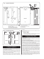
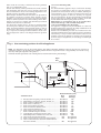
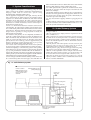
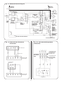
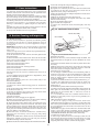
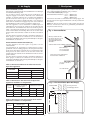
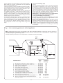
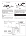
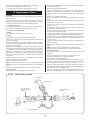
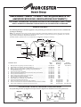
2.1 The multi directional balanced flue kits are available in two
types, low level (WHS Part No: ZAGAS256) and High level (WHS
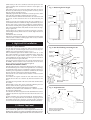
Part No: ZAGAS255). See Fig. 1.
2.2 The flue kits are designed to be used in conjunction with a
standard 12 inch RS flue terminal (WHS Part No: ZAGAS212) or
the shorter 7 inch version (WHS Part No: ZAGAS213). It is
recommended that wherever possible the 12 inch terminal
should be used, as this will give maximum flue noise reduction.
All of the dimensions stated in these instructions assume a
standard terminal. Where a short terminal must be used,
subtract 145 mm from X in section 3.
2.3 The flue kit is able to discharge the products of combustion
to the rear, or at 90 degrees, to the left or right of the appliance.
2.4 When fluing to the rear, the unit will fit into any wall up to a
thickness of 453 mm. However, should the wall thickness
exceed 453 mm or the appliance require positioning further
from the wall then this may be done using up to two Worcester
RS Flue Extension Kits (WHS Part No: ZAGAS214).
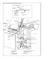
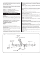
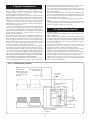
2.5 The flue terminal louvered end cap can be removed to clean
the horizontal flue by removing the screw on its base and
pivoting the end cap forwards and upwards to release the tabs.
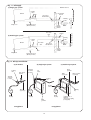
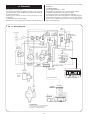
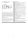
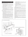
Access to the vertical flue can be gained by removing the flue
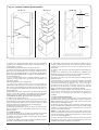
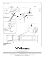
box lid (N). See Fig. 4.
3. Low-level Kit Installation
STANDARD 12 INCH TERMINAL
The flue kit must be fully assembled before fitting to the
appliance.
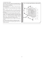
3.1 Make a 170 mm square hole in the wall , for the flue
terminal. The height of the hole centre should be 1023 mm from
the appliance base.
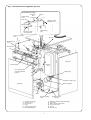
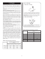
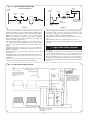
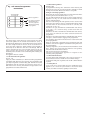
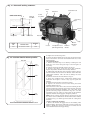
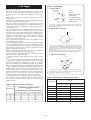
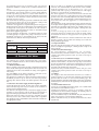
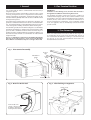
3.2 Before positioning the appliance, the boiler rear flue outlet
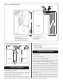
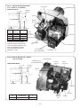
and rear air duct must be blanked off using the plates as shown
in fig 2.
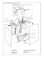
3.3 Undo the three nuts (F)and remove and discard the rear
discharge clamping collar (B)and gasket (C). Replace these with
the solid gasket (H) and blanking plate (G) and secure with the
three nuts (F) ensuring the plate forms a good seal.
3.4 Apply a bead of silicone sealant (supplied) around the inner
edge of the rear duct cover (E) and fix to the rear air duct using
the four screws (D). Bed the fillet of silicone sealant into position
and remove any excess.
3.5 Having decided the position of the appliance, measure the
distance from the outside wall to the rear air duct (distance X
Fig. 1a) for rear outlet, or to the side panel for a right/left outlet
(distance Y fig 1b). For the side outlet calculate X=Y+93 mm.
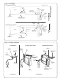
3.6 If X is greater than 453 mm then an extension kit must be
fitted. Two will be required if X is greater than 768 mm, allowing
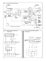
a maximum of X=1081 mm. When fitting an extension kit
remove items 1,2,3 Fig.3 and re-fit to the air duct elbow to allow
the extension to seal against the duct. Follow the relevant parts
of the RS extension kit instructions.
3.7 The terminal must be fitted so that the wall does not overlap
the line indicated on the warning label ( i.e. 15 mm back from
the air inlet holes) and such that there is at least 50 mm
clearance between any part and the terminal guard. The guard is
260 mm deep and will therefore allow the kit to be fitted without
cutting the flue tube (R) where X=347 to 453 mm for the
standard kit, X=662 to 768 mm when one extension section is
used and X=975 to 1081 mm when two extension sections are
used.
3.8 Where X is less than 347 mm using the standard kit, 662
mm using one extension section, 975 mm using two extension
sections or the terminal is to be set back as far as possible, to
give the best appearance, then the aluminium flue tube should
be cut to the required length as described in 3.13 to 3.14.
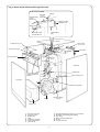
3.9 Remove the duct cover (M). See Fig. 4.
3.10 Pull the insulation off the flue tube (R) and remove the flue
box/tube assembly (O and R) by pulling upwards and waggling
from side to side. Check that the locking bands (P) and (Q) are
slack before removing the flue box!
3.11 Remove the flue box lid (N). Note: the two retaining screws
are held captive to the lid to prevent them dropping into the air
duct. Undo each screw alternately, a little at a time, to prevent
bending the lid.
3.12 Remove the flue tube (R).
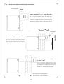
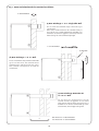
3.13 To shorten the flue tube (R) remove its insulation and cut
off a length l = 453-X for the standard kit, l = 768-X when using
1 extension kit and l = 1081-X when using 2. (See fig 4a).
3.14 Cut the same length l from the insulation and replace it on
the flue tube. Note: It is very important that the insulation is
properly fitted and firmly held in place with the securing straps
as shown, otherwise excessive heat will cause problems with the
burner control box.
3.15 Place a bead of silicon sealant around the flue terminal
spigot (U) and push the clamping end of the flue tube (R) over,
until fully seated. Tighten the locking band (T) ensuring the tube
is parallel to the terminal body.
3.16 To change the direction of the flue system remove the four
screws holding the air duct elbow (S) to the base (V) and refit in
the required direction.
3.17 Seal the air duct to the base (V) using a bead of silicon
sealant (supplied). If the terminal is installed to the left or right
remove the front and rear hole bungs first and replace in the
unused holes.
3.18 Apply a bead of silicon sealant around the inside of both
clamping collars on the flue box (O).
3.19 Replace the flue box (O) in the required direction and push
fully down. Ensure the locking band (P) is positioned with the
screw facing forwards as shown but do not tighten at this stage.
3.20 Ensure the locking band (Q) is positioned with the screw
facing upwards.
3.21 Insert the flue tube/terminal assembly (R, T and U) into the
air duct and push fully back into the flue box clamping collar.
Ensure that the terminal louvered outlet is pointing downwards
as shown.
3.22 Tighten locking bands (P) and (Q) and smear the silicon
sealant, inside the flue box (O), to seal the flue tubes and remove
any excess.
3.23 Replace the flue box lid (N).
3.24 Seal around the flue terminal and the air duct using the
sealing tape supplied as shown in fig 4b.
3.25 Undo the two screws (L) holding the rear air duct top cover
(A) and discard the cover. See Fig. 2. Save the screws to fasten
the air duct base (V) in place.
3.26 Fix the self adhesive duct gasket (K) to the top of the rear
air duct (Z) and the flue collar gasket (J) to the underside of the
flue collar (W).
3.27 Feed the flue terminal assembly through the hole in the
wall and carefully sit the balanced flue kit on top of the boiler
flue outlet plate. See fig 2. Note: Take care not to damage the
seals!