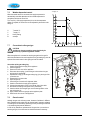
1
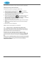
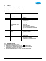
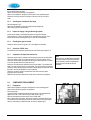
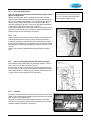
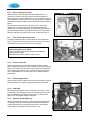
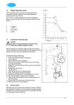
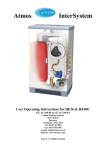
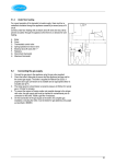
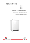
7.6
Weather-dependent control
T supply °C
When the outside sensor is connected, the supply temperature is
automatically controlled dependent on the outside temperature in
accordance with the set control line.
The T set CH (= CH supply temperature) is set via the temperature
display. If required, the control line can be adjusted by the service code.
See §7.3.
X.
Y.
A.
B.
T outside °C
T supply °C
factory setting
example
7.7
Conversion to other gas type
T outside °C
CAUTION
Activities on the gas-containing parts should only be
executed by a qualified registered installer.
When the appliance is connected to another gas type than the type for
which the manufacturer has set the appliance, the gas setting ring must be
replaced. Conversion sets for other gas types can be ordered.
Conversion of the gas setting ring
1. Switch off the electrical supply to the appliance.
2. Close the gas tap.
3. Remove the front cover of the appliance.
4. Disconnect the coupling (1) above the gas valve and turn the gas
mixing pipe (2) backwards.
5. Replace the O-ring (3) and the gas setting ring (4) by the rings of the
conversion set.
6. Reassemble in reverse order.
7. Open the gas tap.
8. Check the gas connections for tightness/ leaks.
9. Switch on the electrical supply to the appliance.
10. Change the parameters c and F to the values given in the table.
11. Now check the setting of the gas/air ratio. (See below)
12. Attach a sticker of the set gas type over the existing sticker on the
gas mixing pipe (2).
13. Apply a sticker of the set gas type at the appliance plate.
14. Remount the front cover of the appliance.
7.8
Gas-air control
Although the gas valve is factory-preset, because of variations in different
boiler installations this setting must be checked and if necessary adjusted.
The setting can be checked by measuring the CO2 percentage in the flues
or by measuring the pressure difference.
In case of any alterations, replacement of the gas valve or conversion to
another gas type, the control must be checked and reset if necessary
41
according to the table below:-
Gas type
Gas category
CO2% at low position (L)
(service and -)
CO2% at high position (H)
(service and +)
CO/CO2 ratio
Gas inlet pressure dynamic (mBar)
Gas inlet pressure static (mBar)
Gas setting ring diameter (mm) HE26
Gas setting ring diameter (mm) HE40C
Minimum speed (% of max)
(parameter c)
Min. starting speed (% of max)
(parameter F)
Note: See also §7.3 (Parameters)
7.9
Natural gas H
2H G20
Propane P
3P G31 (propane)
8.8 – 9.2
9.3 – 9.7
8.6 – 9.6
9.5 – 10.5
0.004 or less
17-25
20
6.95
6.55
0.004 or less
25-45
37
5.35
5.25
25
40
70
50
Setting gas-air control
Setting by measuring the CO2 content of the flue gases
•
A flue gas test point must be mounted right above the appliance in
the flue discharge.
Siemens gas valve & ignition transformer
A.
B.
C.
D.
Dust cap (socket head wrench torx T15)
Setting screw for the low position (socket head wrench torx T15)
Off-set pressure measuring nipple
Inlet pressure measuring nipple
1.
Switch off the appliance using the On/Off button ( - on service
display).
Open the flue gas test point and insert the gas test probe.
Switch on the appliance using the On/Off button.
Set the boiler to the lowest output by simultaneously pressing the
“Service” and “–“ buttons on the operating panel until an L
appears on the service display.
Measure the CO2 value and the CO/CO2 ratio. Check that these
correspond with the values in the table. If the CO2 value does not
correspond with the value in the table, proceed as follows for setting:
Remove the front cover of the appliance.
Remove the dust cap (A) with a torx T15 driver
Using a torx driver (T15), adjust the setting screw (B) to the correct CO2 value
(clockwise higher and counter-clockwise lower).
After measuring and setting, set the boiler to the highest output by simultaneously
pressing the “Service” and “+“ buttons (twice) on the operating panel until an H
appears on the service display.
Measure the CO2 value and the CO/CO2 ratio. Check that these correspond with
the values in the table.
If the high output CO2 is not within the parameters allowed in the chart above,
return to low output and adjust the CO2 setting at low output before returning to
high out put to check it again. Contact the manufacturer if you encounter
difficulties.
Exit the test mode by simultaneously pressing the “+” and “–“ buttons on the
operating panel. Replace the dust cap (A) and close the flue gas test point.
Remount the front cover of the appliance.
2.
3.
4.
5.
6.
7.
8.
9.
10.
11.
12.
13.
42
Caution: On windy days or on installations with a long flue run it is necessary to
replace the front cover of the boiler in order to obtain an accurate CO2 measurement
Setting the gas valve by pressure measurement
This method is less accurate, but usually gives a sufficient result.
1.
2.
3.
Switch off the appliance using the On/Off button ( - on service display).
Remove the front cover of the appliance.
Turn the measuring nipple (C) on the gas valve open with two turns and connect
this through a tube to the plus connection of the pressure gauge.
4. Switch on the appliance using the On/Off button.
5. Set the boiler to the lowest output by simultaneously pressing the “Service” and “–“
buttons on the operating panel until an L appears on the service display.
6. Read the pressure. This should be about – 0.05 mBar (between – 0,1 mBar and 0
mBar). When this is not the case, proceed as follows for setting:7. Remove the dust cap (A) with a torx T15 driver.
8. Set the pressure using setting screw (B) (clockwise higher and counter-clockwise
lower).
9. After measuring and setting, replace the cover cap A and close the measuring
nipple (C) again.
10. Remount the front cover of the appliance.
Caution: Check the measuring nipple (C) for gas tightness.
7.10
Carbon monoxide : carbon dioxide ratio (CO/CO2 ratio)
Atmos recommends that a carbon monoxide : carbon dioxide ratio test is carried out
when the boiler is commissioned. This is best done when the CO2 content of the flue
gasses is measured. See the procedure described in §7.9.
The CO/CO2 ratio at low or high output should be no higher than 0.004.
A CO/CO2 ratio between 0.004 and 0.008 means that the appliance is ‘At Risk’ (AR).
A CO/CO2 ratio above 0.008 means that the appliance is ‘Immediately Dangerous’
(ID)
Where an ‘at risk’ or ‘immediately dangerous’ situation is encountered, measures must
be undertaken to rectify the situation. Particular attention should be given to the gas/air
ratio, the integrity of the flue, or blockage in the heat exchanger. Contact the
manufacturer for assistance.
43
8.
FAULTS
When the controller detects a fault, the red fault LED flashes (above the
Reset button) and a fault code is shown on the Temperature display.
After the fault has been remedied, the controller can be restarted by
pressing the Reset button for 5 seconds.
The following faults are detected and displayed:Temperature
Description
display
10, 11, 12, 13, 14 Sensor fault S1
Possible cause/remedy
•
•
20, 21, 22, 23, 24 Sensor fault S2
•
•
0
1
Sensor fault after self-check
Temperature too high
•
•
•
•
2
Exchange S1 and S2
•
•
4
No flame signal after 4 ignition
attempts
•
•
•
•
•
5
No flame signal after 4 restart
attempts
•
•
•
6
Flame detection fault
•
•
•
8
Fan speed incorrect
•
•
•
•
29, 30
8.1
Gas valve relay fault
•
Check the wires for breaks
Replace S1
Check the wires for breaks
Replace S2
Replace boiler sensor S1 and/or S2
Air in system
Pump does not run
Too little circulation in system, radiators closed,
pump setting too low
Check the cable loom
Replace S1 or S2
Gas tap closed
Incorrect ignition distance
Gas inlet pressure too low or disappears
Gas valve or ignition unit does not receive voltage
Further info can be found on Technical Data Sheet
TDS012 available on www.atmos.co.uk
Condensate discharge blocked
Check setting of gas valve
Further info can be found on Technical Data Sheet
TDS013 available on www.atmos.co.uk
Replace ignition cable + spark probe
Replace ignition unit
Replace controller
Fan rubs against casing
Wiring between fan and casing
Check the wires for poor contact (tacho signal)
Replace fan
Replace controller
Display last fault code.
It is possible to display the last fault code as follows:
•
Set the appliance in the off mode using the On/Off key ( - on the service display).
•
Press the Service key, until the last fault code appears flashing on the temperature display.
When no fault has occurred no code will be displayed.
•
By pressing simultaneously the Service key and the “-“ key the fault code will be erased.
44
8.2
Burner does not ignite
Possible causes
Remedies
Gas tap is closed
Yes 1. Open the gas tap.
No
Air in the gas pipe.
Yes 1. De-aerate the gas pipe.
No
Inlet pressure too low.
Yes 1. Contact the gas company.
No
No ignition
Yes 1. Replace the ignition probe.
No
No spark.
Ignition unit on gas unit faulty
1. Check the cabling.
Yes 2. Check the spark probe
3. Replace the ignition unit.
No
Gas-air control not
adjusted properly.
Yes
1. Check the adjustment,
see Gas-air control.
No
Fan faulty
Yes
1. Check the wiring.
2. Check the fuse.
3. Replace the fan if necessary.
No
Fan blockage
Yes
1. Clean the fan.
No
Gas valve faulty
8.3
1. Replace the gas valve.
Yes 2. Re-adjust the gas valve,
see Gas-air control.
Burner ignites with much noise
Possible causes
Remedies
Inlet pressure too high.
Yes
1. The house gas meter may be faulty.
Contact the gas company.
No
Incorrect ignition distance.
Yes 1. Replace the ignition probe.
2. Check the ignition probe distance.
No
Gas-air mixture not adjusted properly.
Yes
1. Check the adjustment.
See Gas-air control.
No
Weak spark.
1. Replace the ignition probe.
Yes 2. Replace the ignition unit on the gas valve.
3. Check the ignition spark gap.
45
8.4
Burner resonates
Possible causes
Remedies
Inlet pressure too low.
Yes 1. The house gas meter may be faulty.
Contact the gas company.
No
Re-circulation of the flue gases.
No
Gas-air mixture not adjusted properly.
8.5
Yes 1. Check the flue gases and air supply.
Yes
1. Check the adjustment,
see Gas-air control.
No heating (CH)
Possible causes
Remedies
Room thermostat/weather-dependent
control not closed or faulty.
1. Check the wiring.
Yes 2. Replace the thermostat.
3. Replace the weather-dependent control.
No
No voltage (24 V).
1. Check the wiring according to the
diagram.
Yes
2. Check the connector x4.
3. Replace defective controller
No
Pump does not run.
1. Check the voltage.
Yes 2. Check the connector x4.
3. Replace defective pump.
4. Replace defective controller.
No
Burner does not operate on CH: Sensor S1 or S2 faulty.
No
Yes 1. Replace sensor S1 or S2.
See Fault code display: 1 or 2.
Burner does not ignite.
Yes 1. See Burner does not ignite.
46
8.6
Reduced output
Possible causes
Remedies
At high speed, the power has decreased
by not more than 5%.
8.7
Yes
1. Check appliance and flue system
for pollution.
2. Clean appliance and flue system.
CH does not reach the correct temperature
Possible causes
Remedies
Room thermostat settings not correct.
Yes
1. Check the setting and adjust if
necessary: set to 0.1 A.
Yes
1. Raise the CH temperature,
see CH operation.
2. Check the outside sensor for
short circuit: remedy this..
Yes
1. Raise the pump setting or replace
the pump.
Yes
1. Check for circulation: at least 2 or 3
radiators must be open.
Yes
1. Adjust the power,
see Setting maximum CH power.
Yes
1. Descale or flush the heat exchanger
on the CH side.
No
Temperature set too low.
No
Pump does not run well.
Pump setting too low.
No
No circulation in the system.
No
The boiler power is not set well
for the system.
No
No heat transfer due to scaling or pollution
in the heat exchanger.
Table 6. NTC resistances
NTC 12 kOhm / 25°C
T [°C]
-15
-10
-5
0
5
10
15
20
R[ohm]
76020
58880
45950
36130
28600
22800
18300
14770
T [°C]
25
30
35
40
45
50
55
60
R[ohm]
12000
9805
8055
6653
5522
4609
3863
3253
T [°C]
65
70
75
80
85
90
95
100
R[ohm]
2752
2337
1994
1707
1467
1266
1096
952
47
9.
SERVICING THE BOILER AND COMPONENT REPLACEMENT
9.1
SERVICING THE BOILER
The appliance and the system should be serviced annually by a qualified
service engineer.
For appliances connected to propane gas, a six monthly service for the first
two years to simply clean the condensate trap and pipe may be neccessary.
Due to the nature of propane gas, a jelly like substance can build up in the
trap, causing it to become blocked.
9.1.1
Preparation
Switch off the appliance using the On/Off button on the operating panel.
Switch off the electrical supply to the appliance.
Close the gas tap.
Unscrew the two recessed screws left and right at the front underneath the
appliance and lift/remove the front panel. See photo in §4.5.3.
Wait until the appliance and the burner have cooled down. Swing out the
expansion vessel by undoing the clip to raise the vessel slightly.
9.1.2
Checking the heat exchanger and spark ignition probe
Remove the connector from the fan and the ignition block from the gas
valve.
Disconnect the lower gas valve union.
Unscrew the 10 socket screws (Allen socket M8x40) from the front cover
and remove this forwards complete with gas valve and fan.
While removing the front cover do not hold this at the gas valve or the fan.
Be careful not to damage the burner and the fan while removing the
front plate.
The burner does not need any maintenance.
Never clean the burner with a brush or compressed air. This causes
damage to the metal fibre.
Check the spark ignition probe and gently clean any deposits. As the spark
gap cannot be checked directly, use a flat surface across the corner of the
heat exchanger to measure the distance to the probe. See the diagram in
§8.3. The distance should be in the range 27 to 29mm. Replace the probe if
necessary.
Remove the baffles that have been placed crosswise in the fins of the heat
exchanger (HE26 only).
If necessary, clean the baffles and the fins of the heat exchanger from top to
bottom with a brush or with compressed air.
Clean the bottom of the heat exchanger and disconnect and clean the black
plastic condensate sump at the bottom of the flue discharge behind the heat
exchanger.
Reassemble the baffles in the heat exchanger (HE26 only).
Check the silicone gasket of the front cover for damage (hair) cracks and/or
discolouring and replace if necessary.
Mount the front cover to the heat exchanger and attach this with the socket
screws with spring washers. Crosswise tighten the socket screws evenly by
hand. Using an Allen key, tighten the screws so that the front cover is
closed onto the heat exchanger all round the edge, and then tighten them
hand tight (approximately 10 Nm torque).
Make sure that the silicon gasket is well placed around the front cover.
Reconnect the gas union below the gas valve.
Check the sealing ring for damage and replace if necessary.
Fit the connector on the fan and the ignition block on the gas valve.
48
Open the gas tap and check the gas couplings below the gas valve and on
the mounting bracket for leaks.
Switch on the electrical supply to the appliance
Switch on the appliance, using the On/Off button on the operating panel.
Check the front cover and the connection of the fan to the front cover for
leaks.
9.1.3
Checking the condensate discharge
See the diagram in §4.7.
Clean the condensate trap and the condensate discharge pipe.
After cleaning, fill the trap with water.
9.1.4
Inspect air supply / flue gas discharge system
Inspect the air supply / flue discharge system throughout its entirety,
ensuring that it is in sound condition with no damage to the pipes or joints.
Inspect the terminals ensuring that they are clear and unobstructed.
9.1.5
Checking the gas-air control
Check the gas-air control as given in §7.9, and adjust as necessary.
9.1.6
Check the CO/CO2 ratio
The CO/CO2 ratio should be checked on each service. See §7.9 and §7.10
9.1.7
Completion of inspection and service
Check the pressure of the expansion vessel using a pump into the Schroeder
valve if necessary. With a pre charge pressure of 1 bar the pressure in the
expansion vessel should be equal to the CH system water pressure or at least
1 bar if the system pressure is lower than 1 bar.
Check the CH system water pressure shown on the display. This should be at
least 1 bar and at most 2 bar for a cold system. Top up the system if necessary.
Check the central heating system and the hot water supply for leaks and check
the boiler, controls and system for correct operation.
Check the corrosion inhibitor concentration level within the CH system,
topping up when necessary.
Refit the front panel and replace the screws at the bottom of the appliance.
9.2
COMPONENT REPLACEMENT
9.2.1
Preparation
Note
After servicing, the Benchmark Checklist
and Service Record (located at the back
of this manual) must be completed and
signed and the manual left with the
customer.
Switch off the appliance using the On/Off button on the operating panel.
Switch off the electrical supply to the appliance.
Close the gas tap.
Unscrew the two recessed screws left and right at the front underneath the
appliance and lift / remove the front panel. See photo in §4.5.3.
Wait until the appliance and the burner have cooled down.
Note – When removing cables / wires to the controller, the cable clamp must
be released first by unscrewing 2 posidrive screws and the controller hinged
down by unscrewing 2 posidrive screws as shown in diagram §5.3.
49
9.2.2
Gas valve/ ignition block
Note: The gas valve is factory-preset and therefore only Atmos or their
agents can supply these.
Remove the spark ignition block by pulling apart horizontally. Undo the
upper and lower unions, making sure that the ‘O’ rings and gas setting ring
are not lost or damaged (see diagram in §7.7). Replace the gas valve, and
refit the ‘O’ rings, the gas setting ring, the unions and the ignition block.
Note: After replacing the gas valve, carry out the gas analysis adjustments
and the CO/CO2 ratio check as given in §7.9 and §7.10.
If replacing the ignition block, then pull apart as above. Remove the push-fit
cable to the probe and undo the X1 connections at the controller and earth.
Replace the ignition block and make the connections.
9.2.3
Fan
Remove the electrical connector. Undo the upper union from the gas valve.
Undo the two 8mm nuts as shown in the photo. Remove the assembly
including the sealing ring. Undo the three Allen screws (M4x10) to remove
the gas inlet sub assembly. Fit the replacement fan in reverse order. Check
the sealing ring is not damaged and replace if necessary; check that it seals
correctly.
See also §9.2.4 below for appliances fitted with Non Return Valve (flue
gas).
9.2.4
Note for CFS systems with Non Return Valve (flue gas)
When refitting the fan, the NRV MUST be refitted (see diagram). Fold the
silicon valve (1) of the NRV carefully into a U-form.
Place the valve + holder (1+2) into the hole of the front plate, making sure
the valve is placed in the correct position (direction toward the front plate as
shown).Replace the fan + seal back on the front plate, and screw both nuts
(4) tight, making sure the valve stays in the right position.
9.2.5
Controller
If possible, record the parameter settings as described in §7.3. Remove the
display cover and undo the two posidrive screws to drop down the controller
panel as shown in the diagram in §5.3.
Pull apart the connectors and undo the 8mm nut to allow the controller
assembly to be removed and replaced. After replacement, set the required
parameter settings as described in §7.2and §7.3,
50
Note
The ignition block is held on the gas valve
by a Torx T10 screw. Remove this screw
prior to pulling the ignition unit off.
9.2.6
Burner / spark ignition probe
Remove the front cover of the heat exchanger as described in § 9.1.2.
Unscrew the 4 screws shown on the photo to allow the stainless steel
burner mesh to be removed. These screws are Torx 20 (RVS A2 4,2x25”) or
Allen bolt M4x20 (units before 2006). The burner gasket should be checked
and replaced if damaged. Replace the burner mesh assembly and refit the
screws.
The spark ignition probe is shown in the photo in §9.1.2 and also the
diagram in §8.3. To replace the probe, pull off the ignition cable and
unscrew the 2 screws (Allen bolt M4x8). The seal should be checked and
replaced if damaged. Replace the probe and refit the seal and the screws.
Check the spark gap and replace the front cover, as described in §9.1.2.
9.2.7
Flow / return temperature sensors
The supply temperature sensor is located above the return temperature
sensor. The latter is shown in the photo. Disconnect the two pin connector
and release the spring clip. Pull out the sensor and replace.
Note: The replacement of the components below this box
requires the appliance to be drained:CH side – Drain the appliance using the drain tap and drain the
system at the lowest point.
After replacement, refill the appliance as given in § 6.1.
9.2.8
Pressure relief valve
Remove the plastic pipe from the safety discharge. Undo the pressure
sensor capillary and undo the union at the connection with the CH flow pipe.
Remove the pressure relief valve and inlet pipe. Remove the plastic fitting
from the discharge and undo the pipe connection to allow removal of the
valve. Fit replacement valve in reverse order using a sealant suitable for
potable water.
9.2.9
Pressure gauge sensor
Undo the pressure sensor capillary and unscrew the two posidrive screws to
release the cable clamp. Remove the gauge and capillary, and replace.
9.2.10 Pump head
Disconnect the pump wires from the controller (see note in §9.2.1). Undo
two Allen bolts on the Wilo pump head to remove the pump head from the
body. Fit replacement pump head in reverse order. The pump must be
vented via its vent plug after refilling the appliance.
9.2.11 Expansion vessel (HE26 only)
Unscrew the flexible hose connection, making sure that the sealing ring is
not damaged. Unclip the bracket holding the vessel and fit replacement
including the sealing ring. Using the Schroeder valve on the expansion
vessel, and pump if required, check the pressure is 1 bar.
51
10.
TECHNICAL SPECIFICATIONS
Appliance category
Gas inlet pressure
Suitable for gas
B13; B33; C13; C 33; C 43; C53; C63; C83
20 mbar
II2 H3P
Technical data
InterSystem HE 26
InterSystem HE 40C
CH
Heat power input (gross)*
Heat power input (net)*
Heat output at 80/60°C*
Heat output at 50/30°C*
Max. CH water pressure
CH operating pressure
Max. CH water temperature
kW
kW
kW
kW
bar
bar
°C
8.0 – 30.3
7.2 – 27.3
7.0 – 26.2
7.7 – 26.8
3 (see note 1)
1 – 2 (see note 2)
90
8.7 – 47.1
7.8 – 42.5
7.0 – 40.9
Other data
Gas consumption
m3/h
0.85 - 3.25
0.81 – 4.00
V
W
W
W
230
IP44 (B(.)=IP20)
105
40
2.4
230
IP44 (B(.)=IP20)
105
40
2.4
mm
mm
mm
kg
810
450
270
39
810
450
270
37
41-249-05
41-249-07
Electrical data
Mains voltage
Protection class
Consumed power: full load
Consumed power: partial load
Consumed power: standby
Overall dimensions and weight
Height
Width
Depth
Weight
Registratrion
GC registration number
3 (see note 1)
1 – 2 (see note 2)
90
*The maximum CH power is set to 50% of the highest value at the factory (see Setting CH power).
Notes 1 - Safety discharge valve is 3 bar.
2 – Min pressure 1 bar (expansion vessel pre-charge is 1 bar).
52
10.1
Electrical diagram HE26
Connector X4
24V=
Connector X2
230V~
1-3
Cascade control contacts (not available on standard controller)
4-5
External economy switch (for hot water)
6-7
On/off room thermostat 0,1A 24V= and/or Frost thermostat.
6-7-9
Power supply clock thermostat (6= positive, 7=switched live, 9= negative) 24V= max.3VA
8-9
Outdoor sensor 12kOhm/25°C
9-10
Hot water cylinder thermostat (normally closed connections). If used remove link 9-10
11-12
OpenTherm modulating thermostat (When in use 6-7 must be open)
1
230 switched live from room thermostat
2-4
7-8
Mains (2=Live, 4=Neutral)
CH pump (8=Live, 7=Neutral)
Valve underfloor heating (3=Live(brown), 5=Switch (black), 6=Neutral(blue)).
e.g. VC4013 Honeywell 230V~
Three way valve (3=Live (brown), 5=Switch live (black), 6=Neutral(blue)),
(e.g. VC4013 Honeywell 230V~)
PC interface
3-5-6
3-5-6
Connector X5
Notes
1.
2.
3.
F: 5x20mm anti-surge fuse, 2A.
230Vac stat circuit: Available for room stat, etc. The switched live (X2/1) can also be used for S plan or Y plan
circuits (note that the 230Vac live to the Wiring Centre must come from the same fused spur as the 230Vac supply
to the boiler).
OpenTherm: When using an OpenTherm thermostat, 6-7 must not be used.
53
10.2
Electrical diagram HE40C
Connector X4
24V=
Connector X2
230V~
1-3
Cascade control contacts
4-5
External economy switch (for hot water)
6-7
On/off room thermostat 0,1A 24V= and/or Frost thermostat.
6-7-9
Power supply clock thermostat (6= positive, 7=switched live, 9= negative) 24V= max.3VA
8-9
Outdoor sensor 12kOhm/25°C
9-10
Hot water cylinder thermostat (normally closed connections). If used remove link 9-10
11-12
OpenTherm modulating thermostat (When in use 6-7 must be open)
1
230 switched live from room thermostat
2-4
Mains (2=Live, 4=Neutral)
3-6
Blower (power supply)
7-8
CH pump (8=Live, 7=Neutral)
Valve underfloor heating (3=Live(brown), 5=Switch (black), 6=Neutral(blue)).
e.g. VC4013 Honeywell 230V~
Three way valve (3=Live (brown), 5=Switch live (black), 6=Neutral(blue)),
(e.g. VC4013 Honeywell 230V~)
PC interface
3-5-6
3-5-6
Connector X5
Notes
1.
2.
3.
54
F: 5x20mm anti-surge fuse, 2A.
230Vac stat circuit: Available for room stat, etc. The switched live (X2/1) can also be used for S plan or Y plan
circuits (note that the 230Vac live to the Wiring Centre must come from the same fused spur as the 230Vac supply
to the boiler).
OpenTherm: When using an OpenTherm thermostat, 6-7 must not be used.
11.
CE DECLARATION
Declaration of conformity according to ISO IEC GUIDE 22.
Manufacturer:
Address:
Atmos Heating Systems
West March, DAVENTRY, Northants, NN11 4SA
Hereby declares that the application:
Atmos, Type InterSystem HE26
Meets the stipulations of the following directives:
• Machine directive (89/392/EC) as amended in directive (93/68/EC)
• Low voltage directive (73/23/EC) as amended in directive (93/68/EC)
• Directive concerning gas appliances (90/396/EEG)
• Boilers Efficiency Directive for new oil and gas fired central heating boilers
(92/42/EC)
• EMC Directive (89/336/EC) as most recently amended in directive (93/68/EC).
Daventry, 1 November 2011
J.A. Thomason BSc (Eng)
Director
55
56
57
58
59
Atmos Heating Systems
West March
Daventry
Northants NN11 4SA
60
Tel: 01327 871990
Fax: 01327 871905
e-mail: [email protected]
Internet: www.atmos.co.uk