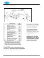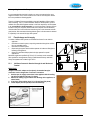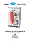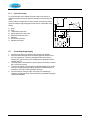
1
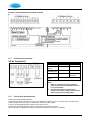
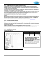
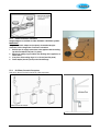
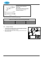
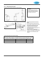
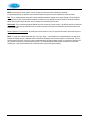
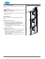
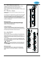
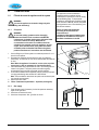
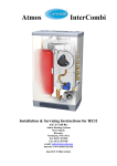
5.1.4 Under floor heating For a good operation of the domestic hot water supply, there must be no undesired circulation through the appliance caused by a second pump of the CH circuit. Connect under floor heating with an electric shut-off valve (two-way valve) to prevent circulation through the appliance when there is no demand for central heating. A. B. C. D. E. F. G. H. 5.2 1. 2. 3. 4. 5. Boiler Pump Thermostatic control valve Spring-operated non-return valve Electrical shut-off valve 230 V ~ Radiators Room/clock thermostat Maximum thermostat Connecting the gas supply Connect the gas pipe to the appliance using the gas valve supplied. Check the boiler's data plate to ensure that the appliance has been set for the correct gas supply. The boiler is supplied for Natural Gas (G20). A propane (G31) gas conversion set is available and an appropriate sticker is included (see §7.7). The meter governor should deliver a dynamic pressure of 20mbar for natural gas or 37mbar for propane. To prevent the ingress of foreign matter and possible damage to the air/gas ratio valve, the gas supply pipe must be checked for contaminants prior to connection to the boiler. Install a gas filter if necessary. On final connection of the gas supply to the boiler, the complete gas installation, including the meter, must be tested for gas tightness and purged as described in BS6891. 21 5.3 Electrical connection CAUTION The appliance requires a 230 V ac 50 Hz mains supply, and must be earthed and connected via a double pole isolating switch fitted with a 3 amp fuse. The switch must be readily accessible, within 1m of the appliance, and provide complete electrical isolation for the boiler and control system. The appliance is supplied factory wired complete with 1 m of mains cable. All electrical connections to the mains supply must be made in full accordance with the current I.E.E. regulations (BS 7671). Isolate the supply by opening the double pole switch when carrying out maintenance activities. 1. 2. Remove the optional pipework cover forwards. Unscrew the screws (A) in order to gain access to the space of the controller (B). The cover plate (& display) hinges open downwards. This gives access to the controller and electrical connections. Consult §10.1and §10.2 for making connections. After having made the required connections, connect the appliance to a switched supply, as given above. 3. 4. 5. Controller Label and Associated Terminals for HE26 22 Controller Label and Associated Terminals for HE40C 5.3.1 4V dc Electrical connections 24V dc Terminals X4 Description Room stat Outside temp sensor OpenTherm modulating stat Frost stat Connector X4 6-7 8-9 Remarks 6 = + 24Vdc 11 - 12 6 - 7 not used 6 -7 Parallel through room stat Power 24Vdc (3VA) 6 = + 24Vdc, 9 = -. Notes 1. Under no circumstances must any electrical 2. 5.3.2 power be input to the room thermostat terminals. It is a volt-free switch. Care must also be taken to avoid induced voltages caused by the running of the thermostat cables along side mains voltage cables. Volt free Room thermostat on/off Connect the room thermostat. See §5.3.1. The terminal block for the connection for a volt free room thermostat, or time clock, is X4 on the control panel. The terminals are wired to the input circuit of the control unit, which has its own 24V dc ‘wetting voltage’. If using a room thermostat with heat accelerator, this must be set at 01A. The maximum permissible resistance of the room thermostat circuit and cable is 15 Ohms. Where a 'wireless' room thermostat is employed, consult the manufacturer’s instructions for installation. 23 5.3.3 Outside temperature sensor (Weather compensation option) The appliance has a connection for an outside temperature sensor. The outside temperature sensor can be applied in combination with an on/off room thermostat or time clock. If not using either of these, a wire link must be made across X4/6 & 7 (or X2/1 & 3) to give continuous operation. Preferably, the outside sensor should be mounted on a North facing wall. It should not be located where it might be affected by (the warmth of) sun light, chimneys, air vents or an open window. To avoid problems with moisture, the sensor should be placed with the cable outlet downwards and the cable looped so that the lowest part of the cable is lower than the hole in the wall. Run the cable back to the appliance, ensuring that holes in walls are sealed, and pass through a suitable cable gland in the bottom of the appliance. Connect the outside temperature sensor cable to the controller as shown in §5.3.1. See Weather-dependent control §7.6 for the setting of the CH temperature line. WARNING! When the boiler is also used to heat a hot water storage tank it is necessary to put in place in arrangement whereby the boiler is delivering a higher flow temperature whenever there is a call for heat for hot water. Contact Atmos for further information or consult Technical Data Sheets TDS003 and TDS010 available on www.atmos.co.uk. 5.3.4 OpenTherm modulating thermostat The appliance is suitable for connecting an OpenTherm modulating thermostat as shown in §5.3.1. The most important function of the modulating thermostat is calculating the supply temperature at a required room temperature in order to make optimum use of the modulating function. With every heat demand, the appliance display shows the required supply temperature. The manual supplied with the OpenThern thermostat should be consulted for more information. NOTE! When connecting an OpenTherm modulating thermostat to a boiler that is also used to heat a hot water storage tank, please contact Atmos for wiring instructions or consult Technical Data Sheet TDS009 available on www.atmos.co.uk. 5.3.5 230Vac Electrical connections 230Vac Terminals X2 Description Mains In Room stat Frost stat Connector X2 Remarks L= 2, N= 4 Earth:see §10.1 1= switch live, 3= live (fused) 1-3 Parallel through room stat Notes 1. The 230Vac stat circuits are alternative to the 24Vdc circuits. If the stat has a neutral connection for heat accelerator, then connect it for more efficient operation. 2. The switched live can also be used for S plan or Y plan circuits (note that the 230Vac live to the Wiring Centre must come from the same fused spur as the 230Vac supply to the boiler). 24 5.4 General Flue Requirements 5.4.1 Flue terminal clearances The flue terminal must be sited with minimum clearance distances as shown in the diagram. A terminal guard must be fitted if the terminal is sited less than 2m above ground level, or above a balcony, or accessible flat roof. Where the flue terminates within 1m of a plastic or painted gutter or within 500mm of painted eaves, then protection should be provided in the form of an aluminium shield at least 1m in length, fitted to the underside of the gutter or painted surface. Please Note! Due to the low flue gas temperature, 'pluming' will occur at the flue terminal. Care should be taken to ensure that the discharge plume will not cause annoyance to the owner or neighbours. It is generally recommended that flues should discharge vertically at roof level. In this position, pluming is not normally a problem. 5.4.2 Flue system The flue system must be installed in accordance with BS5440:1 and the Building Regulations. Horizontal flue pipe runs must always be installed with a minimum slope of 50 mm/metre towards the boiler. This will prevent condensation from gathering in the flue pipe, and will also reduce the chance of icicles forming over horizontal pipe ends in the Winter. 25 Note regarding internal air-flue systems. It is recommended that the boiler is sited on or next to an external wall so as to negate the need to use a void or enclosure as a route for the flue system. Where this is not possible the following applies: There is a Guidance Document available on the safe installation of flue systems within a dwelling. This is a Technical Bulletin reference TB 008 (Edition 2) and is available from Gas Safe Registers website. In brief this requires the air-flue system to be *accessible for visual inspection* by a service engineer. Particular concern focuses on the joints, supports, material and correct slope of the flue installation, which should all be in accord with the instructions given in this document and with good practice. We recommend that the guidance given in this document is adhered to, especially in the case of twin pipe flue systems. 5.5 Flue discharge and air supply A number of different flue systems are available from Atmos for use with this appliance:• 60/100mm concentric system, comprising a standard through the wall flue kit or an extended system. • 80/125mm concentric system. • 80mm twin pipe system which enables separate air intake and flue pipes to be fitted to the appliance. • 80mm PPS and 50mm Mupvc plastic twin pipe system for special applications. Maximum lengths are specified in §5.5.2 to 5.5.6, and must not be exceeded. Other special flue arrangements covering Prefabricated Chimneys and Multi Storey flue systems are included in §5.6 to 5.8. 5.5.1 60/100mm Concentric Standard through the wall Horizontal Terminal IMPORTANT! Using the concentric adapter set (see photo), the standard two-pipe connection can be changed into a concentric connection. 1. Seal the open air supply connections in the appliance with the sealing cap delivered with the set (item C in photo). 2. Remove the sealing ring around the flue discharge in the appliance, as shown below. 3. In its place, fit the sealing ring ø 116 x 110 mm (item B in photo). 4. Fit the adapter (item A in photo) on the flue discharge. 26 6. 7. 8. 9. Mounting 60/100mm horizontal concentric terminal Drill a hole of 110 mm diameter or larger. Cut the terminal to the length required. Slide the terminal into the opening and fit rosettes to cover the opening. Ensure the flue pipe slopes back to the appliance. An alternative telescopic 60/100 horizontal concentric terminal is available from Atmos. The flue should be adjusted to length and the supplied sealing tape applied. NOTE : Atmos also provide anti-plume kits for use with the telescopic flue system. Note: Mark the centre of the hole for the flueNote: at 115mm theof tophole of the Markabove centre onboiler. wall at 100mm above the top of the boiler. 5.5.2 60/100mm Concentric extended flue system Refer to the Atmos Price List for the full list of flue components. Table of Atmos 60/100mm concentric flue equivalent lengths Maximum equivalent concentric length allowed is 10 metres (Note: Includes an allowance for the terminal; ie the terminal can be ignored from the equivalent length) 60/100mm concentric components Equivalent concentric length (M) Remarks 0 45 bend 1.5 0 87 bend 3.0 27 5.5.3 Vertical Concentric connection Straight adapters are available for either 60/100mm or 80/125mm systems. IMPORTANT! Using the concentric adapter set (see photo), the standard two-pipe connection can be changed into a concentric connection. 1. Seal the open air supply connections in the appliance with the sealing cap delivered with the set (item C in photo). 2. Remove the sealing ring around the flue discharge in the appliance, as shown above. 3. In its place, fit the sealing ring ø 116 x 110 mm (item B in photo). 4. Fit the adapter (item A in photo) on the flue discharge. 5.5.4 80/125mm Concentric flue system Refer to the Atmos Price List for the full list of flue components. 28 80/125mm Concentric extension for balcony outlet When the free outlet is hindered by an eave, balcony, gallery or anything else, the concentric terminal must be extended to at least the front side of the overhanging part (see diagram). Table of Atmos 80/125mm concentric flue equivalent lengths Maximum equivalent concentric length allowed is 27 metres (Note: Includes an allowance for the terminal; ie the terminal can be ignored from the equivalent length) 80/125mm concentric components Equivalent concentric length (M) Remarks 0 45 bend 1.5 0 87 bend 3.0 5.5.5 1. 2. Twin-pipe connection Fit the flue pipe to the middle connection on the boiler and fit the air intake pipe to either the left hand or the right hand connection on the boiler. The in-built silicone sealing rings provide airtight connection. When using the right-hand air intake, the sealing cap must be used to cap off the left-hand air intake. 29 5.5.6 80mm twin pipe flue system Refer to the Atmos Price List for the full list of flue components. Terminal The flue discharge at the terminal must be at least 75mm in front of the air intake and the distance between the two pipes at least 75mm. 80mm Twin pipe extensions for balcony outlet When the free outlet is hindered by an eave, balcony, gallery or anything else, the air supply pipe and the flue discharge pipe must be extended to at least the front side of the overhanging part. (In this case the flue discharge must be extended 75mm further than the air supply pipe inlet). When the air supply is not disturbed by obstacles, such as a separating wall, and when the outlet is not at the edge of a building, the air supply pipe does not need extension (see diagram). Table of Atmos 80mm twin flue equivalent lengths Maximum total length allowed is 60 metres (ie Equivalent length of supply pipe + Equivalent length of flue discharge pipe) (Note: Includes an allowance for the terminal; ie the terminal can be ignored from the equivalent length) 80mm components Equivalent length (M) Remarks 0 45 bend 1.5 0 87 bend 3.0 30 5.5.7 Plastic twin pipe flue systems NOTE Consult Atmos for these systems. Use of non-approved flue systems will invalidate the guarantee. For special applications, the appliance can be used with plastic flue pipes, which are available from Atmos as follows: PPS. This is a rigid translucent plastic pipe in 60mm and 80mm diameters, together with a range of fittings. This is suitable for continuous use at 120ºC and is therefore suitable for connection from the appliance to the flue terminal. This must include the 80mm PPS pipe with flue gas test point, which is required for commissioning of the boiler. PPS Flexible. This is a flexible pipe 80mm diameter which can be used for chimney linings, or for difficult vertical runs. Note that it must only be used vertically and MUST NOT be used for horizontal runs because the condensate will accumulate and could block the flue path. Plastic combustion air inlet systems: All plastic pipes can be used for air inlet. The pipe does not need to slope since there is no condensate. NOTE: In longer runs of 80mm plastic flue pipe – 3m long or longer – it is advisable to fit a condensate drain in the flue pipe to facilitate the draining away of condensate before it reaches the alluminium parts of the flue system or the boiler itself. This is to prevent excessive corrosion. Atmos can supply a condensate drain-off fitting for 80mm flue pipe. It incorporates a flue test point and it needs to be fitted into a vertical section of the flue. The condensate drain-off fitting allows connection to solvent weld overflow pipe. A trap must be fitted into the condensate drain to prevent flue gases escaping. 31 5.6 Roof outlet prefabricated chimney Appliance category: C33 When there is little space in a shaft, a roof outlet through a prefabricated chimney may be necessary. The prefabricated chimney must comply with the minimum lengths shown. The supplier must guarantee the proper operation of the prefabricated chimney with respect to wind attack, ice formation, rain ingress, etc. In view of the different models and requirements, the prefabricated chimneys must be adjusted to the local situation: a gas certificate is not required. CAUTION The connection of the air supply and the flue discharge between the appliance and the prefab chimney must be made in pipes of diameter 80 mm. Maximum pipe length See §5.5.6 Mounting of prefabricated chimney The outlet can be made at any place in the pitched or flat roof surface. 32 5.7 Atmos MS System Appliance category: C53 (individual vertical flue and separate horizontal air inlet). CAUTION The air supply (A) in the outside wall must be provided with an Atmos inlet grid. Flue terminals (B) can be individual, or common terminals can be provided for groups of up to 6 flues. Maximum pipe length See §5.5.6. The air supply pipes and flue discharge pipes should be 80mm. Mounting of air supply - horizontal The air supply (A) can be made at any place in the outside wall. 1. Make an opening of diameter 90 mm at the place of the supply. 2. Shorten the air supply pipe to the correct length out of the wall. 3. Mount the Atmos inlet grid and attach this to the pipe. 4. Slide the air supply pipe into the opening and cover the opening with a rosette, if necessary. Mounting flue terminal - vertical 1. Mount a roof tile with shell in a pitched roof surface at the place of the outlet. Mount an adhesive plate suitable for a double-walled flue terminal diameter 80 mm (outside diameter 96 mm) in a flat roof. 2. Slide the double-walled flue terminal from the outside to the inside through the roof terminal. The outlet must protrude at least 500 mm above the roof surface. 33 5.8 Atmos Communal Flue System (CFS) A design service is provided for each application. There are different configurations possible and the main ones are illustrated. CFS-NV Naturally ventilated, working under negative pressure CFS-FA Fan assisted, working under positive pressure – smaller diameter pipes are used 5.8.1 Atmos CFSEO – FA System Appliance category: C83 (Communal Flue System, Exhaust (Flue) Only – Fan Assisted) An air supply from the outside wall and a roof outlet with common discharge system is allowed. The system is fan assisted positive pressure. A nonreturn valve arrangement on each boiler is essential to prevent recirculation of exhaust gases to non operational appliances. There is a common condensate collector at the base of the flue system which must be taken to a suitable drain. Maximum pipe length The maximum length of the air supply and flue discharge pipes between appliance and common flue discharge and air supply together is 75 metres (80mm pipes). Common flue discharge The outlet of the flue discharge can be made at any place in the pitching roof surface, provided that the outlet in the roof surface has the same orientation as the air supply in the outside wall. With a flat roof the outlet of the flue discharge must be made in the 'free' outlet area. 5.8.2 Atmos CFS System Appliance category: C43 CFS – NV or CFS – FA systems are available. The fan assisted positive pressure system allows a more compact installation. Connection from the appliance can be either twin pipe or concentric. There is a common condensate collector at the base of the flue system which must be taken to a suitable drain. CFS – FA systems require a non-return valve arrangement on each boiler, which is essential to prevent recirculation of exhaust gases to non operational appliances. CAUTION For the common flue discharge cover and air supply cover a certificate of incorporation from the Gastec-Gasinstituut is required. Maximum pipe length The maximum length of the air supply and flue discharge pipes between appliance and CFS system together is 75 metres (80mm pipes). 34 6. COMMISSIONING 6.1 Fill and de-aerate the appliance and the system WARNING Connect the appliance to the mains voltage only after filling and de-aerating! 6.1.1 CH system WARNING All new and existing systems must be thoroughly drained and flushed out in accordance with BS7593 requirements. A suitable cleaning agent is Sentinel X400. A corrosion inhibitor should be added and the concentration level checked. The inhibitor should be suitable for the materials used in the appliance, such as copper, brass, stainless steel, steel, plastic and rubber. A suitable product is Sentinel X100. When using these products manufacturer’s instructions must be followed. 1. 2. 3. 4. 5. 6. 8. 9. Failure to install and commission according to the manufacturer’s instructions and complete the Benchmark Commissioning Checklist will invalidate the warranty for Gas Boiler installations in the UK. Use the filling loop to fill the system to a maximum pressure of 1 to 2 bar with a cold system. De-aerate the appliance with the manual air vent (A in diagram). Alternatively, an automatic air vent can be fitted instead of the manual air vent. Note: When the appliance is located at, or near to, the top of the system (eg in a loft), an automatic air vent should be fitted. Vent each radiator and purpose fitted air vent in turn starting with the lowest in the system. The system pressure should be regularly monitored during this process and topped up when required. Air should be vented from the appliance pump by opening the pump’s vent plug and allowing water to bleed for a few seconds. Note: Take care that the water does not splash onto the electric parts (eg controller and terminals). Check all joints for leaks. Fill the condensate trap with water – important (see diagram). 6.1.2 7. Note The appliance must be installed and commissioned in accordance with the manufacturer’s instructions in order to comply with the Building Regs. To demonstrate compliance, the Benchmark Checklist (located at the back of this Manual) must be completed and signed at the time of commissioning, and left with the customer. Gas supply Purge the gas supply if necessary via the inlet pressure measuring nipple on the gas valve. Check the connections for leaks. Check the inlet pressure. See §7.8 Gas-air control. 35 6.2 Commissioning of the appliance After having carried out the above operations, the appliance can be commissioned. 1. Switch on the electrical supply to the appliance. The appliance may carry out a self-test as determined by the controller: 2 (on service display). After completing the self-test, a horizontal mark will appear in the service display: - . 2. Press the on/off button in order to put the appliance into operation. The boiler is heated and on the service display appear 3 , 4 , 7 . 3. Set the pump position on the basis of the set maximum power and the resistance of the system on the water side. For the head of the pump and the pressure loss of the appliance, see §7.5. 4. Set the room thermostat higher than the room temperature. The appliance will now switch to CH operation: 5 on service display. 5. Check the gas-air control as described in §7.8 and §7.9, and adjust as necessary. 6. Heat the system and the appliance to about 80ºC. 7. Check the temperature difference between the supply and return of the appliance and the radiators. This should be about 20°C. At this stage set the maximum power on the service panel. See Setting of maximum power. If necessary, change the pump position and/or the radiator valves. The minimum flow-through is:• 200 l/h at a set power of 7.0 kW • 750 l/h at a set power of 26.2 kW • 1150 l/h at a set power of 40.0 kW 8. Switch off the electrical supply to the appliance. 9. De-aerate the appliance and the system after cooling down. (fill up if necessary) 10. Check the heating system for proper operation. 11. Check the burner's gas rate using the gas meter and a stopwatch. HE26: On the maximum input of 32kW, the time taken to use 0.032 m³ (1.130 ft³) of gas should be 33 seconds (± 2 seconds). When timing 1 ft³ on the meter, the equivalent is 29 seconds. When counting the litres over a 2 minute period this is equivalent to 116 litres. The boiler can be set to the highest output by simultaneously pressing the “Service” and “+“ buttons (twice) on the operating panel until an H appears on the service display. Leave a hot tap running to disperse the heat. Exit the test mode by simultaneously pressing the “+” and “–“ buttons on the operating panel. HE40C: On the maximum input of 47.1kW, the time taken to use 0.040 m³ (1.413 ft³) of gas should be 33 seconds (± 2 seconds). When timing 1 ft³ on the meter, the equivalent is 23 seconds. When counting the litres over a 2 minute period this is equivalent to 145 litres. The boiler can be set to the highest output by simultaneously pressing the “Service” and “+“ buttons (twice) on the operating panel until an H appears on the service display. Leave a hot tap running to disperse the heat. Exit the test mode by simultaneously pressing the “+” and “–“ buttons on the operating panel. 12. Instruct the User about filling, de-aerating and the operation of the heating system. 36 Note The controls on the display for ‘hw’ are not applicable for the HE26 & HE40C. Remarks The appliance has been provided with an electronic controller that ignites the flame and continuously monitors this at each heat demand from the heating system. The circulation pump starts running at each heat demand of the boiler. The pump has an overrun time of 1 minute. The overrun time can be changed if necessary. See Installer settings. The controller will automatically run the pump for 10 seconds, once every 24 hours, to prevent it from getting stuck. This activation of the pump takes place at the time of the last heat demand 24hrs later. In order to change this time, set the room thermostat higher for a while at the desired time. Step modulation is set to function (factory setting) so that the power/speed is increased gradually from the minimum (parameter c). This provides the best CH operation. However if the appliance is being used only for heating an indirect hot water tank or for heating fan convectors, the step modulation can be turned off. The appliance will then start almost immediately at the maximum setting and the system will heat up faster. • • • • 6.3 System Shutdown CAUTION Drain the appliance and the system when the mains voltage has been disconnected and there is a chance of freezing. 1. 2. Drain the appliance using the drain tap. Drain the system at the lowest point. 6.3.1 Frost protection In order to avoid freezing of the condensate discharge pipe, the appliance should be installed in a frost-free room. • In order to avoid freezing of the appliance (heat exchanger), it has an appliance frost protection. When the temperature of the heat exchanger drops to 5ºC, the burner will be activated and the pump will start running until the temperature of the heat exchanger reaches10ºC. • When the system (or a part thereof) can freeze, a frost thermostat should be installed in the area to be protected. Connect this according to the wiring diagram. See §10.1 and §10.2. Note! The external frost thermostat is not active when the appliance has been switched off at the operating panel or when the mains voltage has been interrupted. • 37 7. SETTING AND ADJUSTMENT The functioning of the appliance is mainly determined by the (parameter) setting in the appliance controller. A part of this can be set directly via the operating panel, while another part requires an Installer code to be entered before settings can be changed. 7.1 Directly via operating panel The following settings can be made directly via the operating panel. Appliance on/off The appliance is activated by means of the On/Off button. When the appliance is working, the green LED will be lit. When the appliance is off, one bar on the service display ( - ) is shown to indicate the presence of voltage. Adjustment of CH supply temperature Press the Temperature button for approx 2 seconds until the LED CH and the display start to flash (the display shows the set temperature). Change the temperature using the “+” and “-“ buttons, adjustable between 30ºC and 90ºC. Press the Reset button to store the changes (or press the On/Off button to close the menu without storing the changes). Note: After 30 seconds of no action, the changes will automatically be stored and the controller will return to normal. Reset button When the controller detects a fault, the red fault LED flashes (above the Reset button) and a fault code is shown on the Temperature display. (Note: On appliances produced before Nov 07, the red LED is lit and a flashing fault code is shown in the service display). The appliance can be restarted by pressing the Reset button for 5 seconds. Check the nature of the fault by means of the fault codes under §8 and solve the problem, if possible, before resetting the appliance. 7.2 Settings through the service code The controller of the appliance has been set in the factory according to the parameters of §7.3. These parameters can only be changed with the service code. Proceed as follows to activate the program memory:1. Set the appliance in the off mode using the On/Off button ( - on the service display). 2. Simultaneously press the Service and Reset buttons, until a 0 appears on the service and the temperature displays. 3. Using the “+” and “-“ buttons, set 15 (service code) on the temperature display. 4. Use the “Service” button to set the required parameter on the service display. 5. Using the “+” and “-“ buttons, adjust the parameter to the required value on the temperature display. 6. After having entered all required changes, press the “Reset” button until P appears on the service display (until - appears on the service display for appliances produced before Nov 07). 7. Switch on the appliance again using the “On/Off” button. The controller has now been reprogrammed. Note: By pressing the Temperature button, the factory settings of the parameters are restored (can only be done if the service code has been set). 38 7.3 Parameters Par. Setting 0 Service code [15] 1 System type 2 CH pump continuous 3 Set CH power 4 5 A Set max power Min. supply temperature of the control line Min. outside temperature of the control line Max. outside temperature of the control line CH pump overrun time after CH operation CH pump overrun time after external HW tank operation Position of three-way or two-way valve b 6 Factory setting Description InterSystem HE 26 HE 40C Access to installer settings. The service code must be entered (=15). 1 1 0 = standard 1 = heating only operation + indirect hot water tank 2 = hot water only operation 3 = heating only operation 0 0 0 = pump normal with overrun 1 = pump on continuously; 2 = n/a 50 99 Setting maximum CH load, range c – 99% (or 100 if button pressed again when 99 reached) 50 99 Setting maximum power (can be increased to 99) 25 25 Setting range 10°C to 25°C (Weather-dependent control) -7 -7 Setting range -9°C to 10°C (Weather-dependent control) 25 25 Setting range 10°C to 30°C (Weather-dependent control) 1 1 Setting range 0 - 15 minutes 2 2 Setting range 0 - 15 minutes (n/a) 0 0 HW booster 0 0 C Step modulation 1 1 c Min speed in CH operation 30 30 d Min fan speed in HW operation 30 30 E 10 10 E. Min. supply temperature during OT demand OT response 0 = output signal given for CH operation (n/a) 1 = output signal given for HW tank operation (n/a) 2 = output signal given for DHW and for CH operation 0 = disabled 1 = enabled 0 = step modulation off during CH operation 1 = step modulation on during CH operation Setting range 25 to 50% of fan speed (Note: For propane or for appliances with flue non-return valve, set 40) Setting range 25 to 50% (Note: For propane or for appliances with flue non-return valve, set 40) Setting range 10°C to 60°C. (OT = OpenTherm stat) 1 1 F Starting speed CH 70 50 F. Starting speed DHW (not applicable) Max. fan speed 70 50 45 65 CH supply temperature when heating DHW tank Heating delay after hw use Minimum switch off time during CH operation 85 85 0 5 0 5 7 8 9 h n o P 0 = Ignore the OT demand if it is lower than parameter E 1 = Set the value at parameter E, if the OT demand is lower 2 = OT device is switched off and the room stat functions as an on/off switch, with the supply temp set at the appliance. Setting range 50 to 99% (Note: For propane, set 50). This parameter sets the fan speed for ignition and post purge. Setting range 50 to 99% (Note: For propane, set 50). This parameter sets the fan speed for ignition and post purge Setting range 40 to 50 (40 = 4000 rpm) for HE 26 or 60-70 for HE 40C. The absolute maximum speed can be set through this parameter. Supply temperature during indirect hot water tank heating Setting Range 60°C to 90°C (n/a) (0 to 15 mins). Setting range 0 to 15 minutes (anti cycling function) 39 7.4 Setting maximum CH power The maximum CH power is set to 50% (for HE26) or 99% (for HE40C) in the factory. When the CH system requires more or less power, the maximum CH power can be changed by adjusting the fan speed. See table parameter 3, set CH power. This table gives the relation between the fan speed and the appliance power. Setting CH power Required CH power (approx kW) HE26 HE 40C 26.2 23.5 21.9 18.9 15.8 12.7 9.5 Setting on service display (% of the maximum speed) 100 90 ± 83 80 70 60 50 40 30 40.9 36.8 34.5 32.7 28.6 24.5 20.5 16.4 12.3 Pressure loss/pump lift (m head) WILO RS 15/4.1 (HE26) Flow (litres/hr) Caution The power slowly increases while burning (modulation by time) and decreases as soon as the set supply temperature is reached. 7.5 Setting pump position The switch for setting the pump position is located on the connecting box of the CH pump 1. Set the pump position on the basis of the set maximum power and the resistance of the system on the water side. See diagram: Pressure loss and pump lift, type Ups 50-130, positions 1, 2 and 3. 2. Check the temperature difference between the supply and return of the appliance: this should be about 20°C. The minimum flow-through 200 l/h 750 l/h 1170 l/h Set power 7.0 kW 26.2 kW 40.9 kW WILO RS 15/7-3 (HE40C) Flow (litres/hr) A. B. AA I II III X Y 40 (Not applicable) InterSystem HE26 InterSystem HE 40C Pump position 1 Pump position 2 Pump position 3 Flow-through in litres/hr Pressure loss / pump lift in metres head AA