1
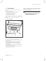
For the owner
Operating manual
ecoCRAFT
Modular Gas Condensing Boiler
GB
VKK GB 806/2-E-H
VKK GB 1206/2-E-H
VKK GB 1606/2-E-H
VKK GB 2006/2-E-H
VKK GB 2406/2-E-H
VKK GB 2806/2-E-H
Contents
1 Notes on the documentation
Contents
1
1
1.1
1.2
1.3
1.4
Notes on the documentation . . . . . . . . . . . . .
Storage of the documents . . . . . . . . . . . . . . . . . . .
Symbols used . . . . . . . . . . . . . . . . . . . . . . . . . . . . . .
CE label . . . . . . . . . . . . . . . . . . . . . . . . . . . . . . . . . . .
Identification plate . . . . . . . . . . . . . . . . . . . . . . . . . .
2
2
2
2
2
2
Safety instructions . . . . . . . . . . . . . . . . . . . . .
3
3
3.1
3.2
3.3
3.4
3.4.1
3.4.2
3.5
Notes on the installation and operation . . . .
Intended use . . . . . . . . . . . . . . . . . . . . . . . . . . . . . . .
Requirements of the installation site . . . . . . . . . .
Care . . . . . . . . . . . . . . . . . . . . . . . . . . . . . . . . . . . . . .
Recycling and disposal . . . . . . . . . . . . . . . . . . . . . .
Appliance . . . . . . . . . . . . . . . . . . . . . . . . . . . . . . . . . .
Packaging . . . . . . . . . . . . . . . . . . . . . . . . . . . . . . . . .
Energy saving tips . . . . . . . . . . . . . . . . . . . . . . . . . .
4
4
4
4
4
5
5
5
4
4.1
4.1.1
4.1.2
4.2
4.3
4.4
4.5
6
6
6
6
7
7
8
4.6
Operation . . . . . . . . . . . . . . . . . . . . . . . . . . . . .
Checks before start-up . . . . . . . . . . . . . . . . . . . . . .
Opening the shut-off valves . . . . . . . . . . . . . . . . . .
Checking water level . . . . . . . . . . . . . . . . . . . . . . . .
Overview of the operating field. . . . . . . . . . . . . . .
Switching the unit on and off . . . . . . . . . . . . . . . .
Operator field with multi-function display . . . . .
Settings for the heating and hot water
operation . . . . . . . . . . . . . . . . . . . . . . . . . . . . . . . . . .
Diagnosis mode . . . . . . . . . . . . . . . . . . . . . . . . . . . .
5
5.1
Troubleshooting . . . . . . . . . . . . . . . . . . . . . . . . 11
Resetting a fault . . . . . . . . . . . . . . . . . . . . . . . . . . . . 11
6
6.1
6.2
6.3
6.4
6.5
Care and maintenance . . . . . . . . . . . . . . . . . .
Care . . . . . . . . . . . . . . . . . . . . . . . . . . . . . . . . . . . . . .
Maintenance . . . . . . . . . . . . . . . . . . . . . . . . . . . . . . .
Checking the system pressure . . . . . . . . . . . . . . . .
Filling unit/heating installation . . . . . . . . . . . . . . .
Measuring and checking work by the chimney
sweep . . . . . . . . . . . . . . . . . . . . . . . . . . . . . . . . . . . . .
7
7.1
7.2
10
10
12
12
12
12
12
13
Customer service and warranty . . . . . . . . . . . 13
Vaillant service . . . . . . . . . . . . . . . . . . . . . . . . . . . . . 13
Vaillant warranty . . . . . . . . . . . . . . . . . . . . . . . . . . . 13
Notes on the documentation
The following information is intended to help you
throughout the entire documentation.
Further documents apply in combination with this
operating manual.
We accept no liability for any damage caused by
failure to observe these instructions.
Other applicable documents
All operating manuals of structural parts and
components of the installation must be observed when
operating the condensing gas boiler. These operating
manuals are included with the individual structural parts
of the installation and the ancillary components.
1.1
Storage of the documents
Please pass this operating manual on to the owner of
the system in order for him or her to store it so that it is
available whenever it is required.
1.2
Symbols used
Please observe the safety instructions in this operating
manual!
Danger!
Immediate risk of serious injury or death
Caution!
Potentially dangerous situation for the product
and environment.
Note!
Useful information and instructions
• Symbol for a necessary task
1.3
CE label
The CE designation documents the fact that the units
comply with the basic requirements of the gas
equipment directive (Council Directive 90/396/EEC) and
the directive concerning the electromagnetic
compatibility (Council Directive 89/336/EEC).
The appliances meet the basic requirements of the
efficiency requirements directive (Council Directive
92/42/EEC).
1.4
Identification plate
The identification plate is mounted on the front of the
boiler under the front cladding. It becomes visible after
the front section of the cladding is removed.
2
Operating manual ecoCRAFT
Notes on the documentation 1
Safety instructions 2
Danger!
Risk of poisoning and explosion due to a
malfunction
Never put the safety devices out of operation or
tamper with them so as to impair their
function.
Fig. 1.1 Identification plate
2
Safety instructions
What to do in an emergency
Danger!
If you smell gas, risk of poisoning and explosion
due to a malfunction
If you smell gas:
• Do not switch lights on or off.
• Do not use any other electrical switches.
• Do not use a telephone in the area of the hazard.
• Do not use naked flames, such as matches or cigarette
lighters.
• Do not smoke.
• Close the gas stop cock.
• Open the windows and doors.
• Warn other residents.
• Get out of the house.
• Notify your gas supplier or a suitably qualified heating
engineer.
Safety instructions
Always observe the following safety instructions and
regulations.
Danger!
Inflammable mixtures of gas and air may
explode
Do not use or store explosive or easily
flammable substances such as petrol or paint in
the same room as the appliance.
Operating manual ecoCRAFT
Therefore, do not attempt any modifications:
- To the appliance
- Around the appliance
- To the gas, air, water and electricity supply pipes
- To the flue pipes
- and to the safety valve and the drain pipe for the
heating water.
This also applies to alterations to structural elements in
the vicinity of the appliance which might affect its
operational safety.
For example:
- Keep all openings for air and flue gas free. Make sure,
for example, that any temporary covers used when
performing work on the outside wall are removed.
For alterations to the appliance or to its environment,
you must refer to the suitably qualified heating engineer
which is responsible for it.
Caution!
Inappropriate alterations can cause damage
Under no circumstances should you ever
attempt to make alterations to the gas heating
boiler or other parts of the system.
Never try to carry out maintenance work or
repairs on the appliance yourself.
- Do not damage or remove seals on components. Only
suitably qualified heating engineer or our customer
service may removed sealed components.
Caution!
Risk of damage!
Do not use sprays, solvents, chlorinated
cleaning agents, paint, adhesives or similar
substances in the vicinity of the appliance.
These substances can cause corrosion,
including in the flue system.
Installation and setting
The appliance may only be installed by an suitably
qualified heating engineer. This engineer also assumes
responsibility for installing the appliance properly and
putting it into service for the first time.
He is also responsible for inspection, maintenance and
repairs to the appliance, and alterations to the set gas
volume.
3
2 Safety instructions
3 Notes on the installation and operation
Filling pressure of the heating system
The filling pressure of the heating installation should be
checked at regular intervals.
Emergency power supply
Your specialist technician connected your gas heating
boiler to the electrical mains during installation.
If you wish to keep the unit running with an emergency
power supply in the event of a power failure, the
technical specification of the unit (frequency, voltage,
earthing) must be in agreement with the mains power
supply, and must be rated to at least the power
consumption of your unit. Please consult your heating
engineer on this subject.
Frost protection
If you are going to be away during a cold period, make
sure the heating system remains in operation and that
the rooms are sufficiently heated.
Caution!
The frost protection and monitoring devices are
only active if the mains switch of the unit is
depressed and shows a green light.
Addition of frost preventative medium to the
heating water is not permitted. Otherwise it
could result in damage to seals and diaphragms
as well as to noises in the heating operation.
Vaillant assumes no liability for this and such
consequential damages.
Your unit has a frost protection function: If the heating
flow temperature falls below 10°C with the main switch
turned on, the appliance starts up and heats the entire
heating circuit to approx. 20 °C.
Caution!
Through-flow of the entire heating installation
cannot be guaranteed.
Another way to protect the heating system and the
appliance from frost is to drain them. You must ensure
that the system and the appliance are completely
drained.
Contact your heating engineer.
3
Notes on the installation and
operation
3.1
Intended use
The Valliant ecoCRAFT units are state-of-the-art
appliances which have been constructed in accordance
with recognised safety regulations. Nevertheless, there
is still a risk of death or serious injury to the user or
others or of damage to the device and other property in
the event of improper use or use for which it is not
intended.
The units are intended as heat generators for hot water
- central heating installations. Any other use or extended
use is considered to be improper. The manufacturer or
supplier is not liable for any resulting damage. The user
alone bears the risk.
Intended use includes the observance of the operating
and installation manual and all other applicable
documents, as well as adherence to the maintenance
and inspection conditions.
Caution!
Any improper use is forbidden.
The appliances must be installed by a heating engineer,
who is responsible for adhering to the existing
regulations, rules and guidelines.
3.2 Requirements of the installation site
The Vaillant gas heating boilers ecoCRAFT must be
installed in boiler rooms. Ask your heating engineer
which national regulations must be observed.
The entire installation site should be frost-proof.
Observe the specified frost protection measures in
Chapter 2 if you are unable to ensure this requirement.
Note!
It is not necessary to keep a clearance between
the appliance and combustible materials or
components, since at the rated heating power
of the appliance the temperature at the surface
of the housing is always lower than the
maximum allowed temperature of 85 °C.
When installing the unit, the recommended minimum
distances given in the maintenance manual should be
observed for reasons of accessibility.
3.3 Care
• Clean the exterior of your appliance with a damp cloth
and a little soap.
Note!
Do not use scouring or cleaning agents, which
may damage the housing or plastic fittings.
4
Operating manual ecoCRAFT
Notes on the installation and operation 3
3.4 Recycling and disposal
Both your Valliant ecoCRAFT gas heating boiler and its
packaging consist mainly of recyclable raw materials.
3.4.1 Appliance
Make sure the old appliance and any accessories are
disposed of properly.
3.4.2 Packaging
Please leave the disposal of the transport packaging to
the qualified servicing company which installed the
appliance.
Note!
Please observe the applicable national legal
regulations.
3.5 Energy saving tips
Installing a weather compensator
Weather compensators regulate the heating supply
temperature according to the outside temperature. No
more heat is created than is required. The designated
heating feed temperature for the corresponding outside
temperature must be set on the weather compensator.
This setting must not be greater than that required by
the design of the heating installation.
The correct setting is normally undertaken by the
heating engineer. Desired heating and set-back phases
(e.g. at night) are automatically turned on and off by
using integrated time programs.
Weather compensators combined with thermostat valves
are the most economical form of heating regulation.
Reducing the heating system
Reducing the room temperature at night and in your
absence. This is best and most reliably realised using
regulators with customisable time programs.
At such times, set the room temperature approx. 5 °C
lower than during full heating times. Reduction of more
than 5 °C brings no additional energy saving, because
then increased heating capacities would be needed for
the next full heating period. Only for longer absences,
e.g. holidays, is it worthwhile to further lower the
temperatures. However, in winter, make sure that there
is adequate frost protection.
Room temperature
Set the room temperature only as high as would be
enough for your comfort level. An extra degree would
mean increased energy consumption of about 6%.
Adjust the room temperature according to the purpose
of use of the room. For example, normally, it is not
required that bedrooms or seldom used rooms are
heated to 20 °C.
Operating manual ecoCRAFT
Setting the operating mode
In warmer seasons, when the apartment needs no
heating, turn the heating to summer mode. The heating
mode is then shut off, however, the device or the plant
remains ready for operation for water heating.
Uniform heating
Often, in an apartment with central heating, only one
room is heated. Through the encapsulation surfaces of
this room, i.e. walls, doors, windows, roofs, floors, the
unheated adjoining rooms are also heated in an
unregulated manner, i.e. unwanted heat energy is lost.
The capacity of the radiator in this one heated room is
obviously not enough for such an operating mode.
Consequently, the room can not be heated satisfactorily
and an uncomfortable feeling of coolness prevails (the
same effect is produced when doors between heated or
unheated or slightly heated rooms remain open).
This is incorrect saving: The heating is in operation and
still the room temperature is not comfortably warm.
Increased levels of heating comfort and more effective
operation are achieved if all rooms in an appartment are
heated evenly and in accordance with their utilisation.
The building structure can, by the way, also suffer if
sections of the building are unheated or only partially
heated.
Thermostat valves and room thermostat
It should be a matter of course, today, that all radiators
be fitted with thermostatic valves. They exactly maintain
the set room temperature. You can adjust the room
temperature to suit your individual requirements and
ensure effective operation of your heating installation
using the thermostatic valves in combination with a
room temperature regulator (weather compensator).
In the room where the room temperature regulator is
located, all the radiator valves should be fully opened
since otherwise the two regulating systems will work
against each other and the regulation quality can be
affected.
The following actions by the user are seen quite often:
As soon as the temperature in the room gets too hot the
thermostatic valves are turned down (or the room
thermostat is set to a reduced temperature). If it gets
too cold again after a time, the thermostatic valve is
opened up again.
This is not necessary since the temperature regulation
system takes over this task via the thermostatic valve: If
the room temperature rises above the value set on the
sensor head, the thermostat valve shuts off
automatically, when the temperature drops below the
defined value, it opens again.
5
3 Notes on the installation and operation
4 Operation
Do not cover regulators
Do not cover your regulators with furniture, drapes or
similar objects. The room air must circulate unhindered.
Covered thermostat valves can be equipped with remote
sensors and thus still work.
Appropriate hot water temperature
The warm water should only be heated up to the extent
that is necessary for use. Any further heating results in
unnecessary power consumption and hot water
temperatures of more than 60 °C also lead to increased
lime scale production.
Energy-conscious use of water
Energy-conscious use of water can reduce your bills
considerably.
For example, taking a shower instead of a bath: Whereas
about 150 litres of water are required for a bath, a
modern shower equipped with water saving fittings only
requires a third of this water quantity.
By the way, a dripping water tap wastes up to 2000
litres of water and a leaking toilet flush up to 4000 litres
of water each year. On the other hand, a new seal only
costs a few cents.
Run circulation pumps only if needed
Hot water piped systems are often fitted with so-called
circulation pumps. These provide continuous recirculation of hot water in the piping system so that hot
water is immediately available, even at drawing-off
points which are located far away.
These circulation pumps can also be used with the
Vaillant ecoCRAFT. There is no doubt that they provide
increased comfort for hot water heating. Please bear in
mind, however, that these pumps consume electricity.
And circulating hot water that is not used cools off when
passing through pipes and then needs to be reheated.
Therefore, circulation pumps are to be operated only
when hot water is actually needed for the household.
Individual time programmes can be set using timers
which most circulation pumps have fitted to them or
with which they can be retro-fitted. Weather
compensators often have ancillary functions for
controlling circulation pump timings. Ask your heating
engineer about this.
4
Operation
4.1
Checks before start-up
4.1.1
Opening the shut-off valves
Note!
The shut-off valves are not included in the
scope of supply of your unit. They are fitted by
your heating engineer in the installation. He
should show you the location and how to
operate these components.
4.1.2 Checking water level
• Check the water level (fill pressure) of the installation
at the pressure gauge external to the boiler.
Your heating engineer has shown you the location of the
pressure gauge. It is not integrated into your unit. For
the heating system to operate properly, the indicator on
the pressure gauge should be at approx. 3 bar when the
system is cold. If it is less than 0.8 bar, then water
should be added.
There is a water pressure switch integrated in the unit
which prevents the unit from starting up if the system
pressure < 0.2 bar. This is shown in the display as E26.
At water pressures > 0.8 bar the fault display disappears.
If the heating system extends over several storeys, the
system may require a higher filling pressure. Ask your
engineer for details.
Ventilating residential spaces
During the heating period, open windows only for
ventilation and not for temperature regulation. A brief
impact-ventilation is more effective and energy-saving
than windows that are kept open for a long time. We
recommend that the windows be opened fully for a short
period. During ventilation, close all thermostat valves in
the room or set the room regulator to minimum
temperature. In this way, there will be adequate
ventilation without unnecessary cooling and energy loss
(e.g. by the heating switching on during the ventilation
procedure).
6
Operating manual ecoCRAFT
Operation 4
4.2
Overview of the operating field
4.3
Switching the unit on and off
1
2
3
4
5
6
1
7
8
9
Fig. 4.1 Controls
Fig. 4.2 Switching the unit on and off
The operating elements have the following functions:
1/2
3
4
5
6
7
8
9
+/- buttons: After the parameters have been
called up, the buttons "+" and "-" are used to
change the individual values.
OK button: All changes must be stored by pushing
the OK button. The storing is confirmed by the
figures flashing.
Information button - i: After calling up the
required mode, the individual parameters of the
specific mode can be called up by briefly pushing
the i-button.
Reset button: A malfunction, indicated by a
flashing read-out on the display, is reset by
pushing the reset button. If the fault reappears,
then customer service must be informed.
Display for indication of the current operating
mode, the menu level or specific additional
information
Mode button for selection of the various menu
levels.
Interlock displays for the individual burner
modules (fault resolution see Chapter 5.1).
Button for switching the unit on and off
Caution!
The mains switch may only be actuated if the
heating installation is properly filled with water.
If this is not complied with, damage to the
pump and heat exchanger may occur.
Use the switch (1) to switch the appliance on and off:
When the button (1) is depressed and is lit up, the unit is
switched on and has a power supply.
When the button (1) is not depressed and is not lit up,
the unit is switched off and is isolated from the mains.
Caution!
The frost protection and monitoring devices are
only active if the mains switch of the unit is
depressed and shows a green light.
In order not to switch off this safety device, you should
switch your heating unit on and off using the regulator.
Information concerning this will be found in the relevant
operating manual.
Note!
For longer periods out of commission (e.g. for
building renovation work) you should turn the
gas valve off. In this connection, please refer to
the instructions in Chapter 2 concerning frost
protection.
Operating manual ecoCRAFT
7
4 Operation
4.4
Operator field with multi-function display
1
The following displays occur under normal operating
conditions:
Operation
code
0
1
2
3
4
5
6
7
8
9
Description of functions
Standby, no heating function
The fan on the relevant module starts up and
prevents the burner chamber
Ignition is active, the burner ignites
The burner burns in heating mode
The burner burns in hot water mode
The air pressure monitor responds
Regulator switch-off of the burner in heating
mode
Pump overrun, heating pump
Pump overrun, charging pump hot water cylinder
Regulator switch-off of the burner in hot water
mode
Table 4.1 Operation codes
In the event of a fault, the fault signal flashes alternately
with the basic display (see Chapter 5).
Fig. 4.3 Display in normal operation
The ecoCRAFT units are fitted with a digital information
and analysis system. This system provides information
on the operating status of your appliance and helps you
deal with problems.
In the ready for operation mode and in burner operation,
the display shows a single figure operating code. This
indicates the current operating condition of the boiler
and the current temperature at the feed manifold, e.g.:
"3 45" = Burner in heating operating mode "3",
forward flow temperature
"45 °C"
Operational displays
The operational display provides information on the
operational condition of your unit. The operation codes
1, 2 and 5 appear at the start of each individual module.
The number of the individual module is preset on the
operational display.
8
Operating manual ecoCRAFT
Operation 4
Status or fault
display
Overview of the operating levels
Hotwater pre-set
Parameter No.
Operation mode
Parameter No.
Setting the maximum
temperature
Parameter No.
Call-ups and settings
Setting
Factory
setting
(max.)
Min
Factory setting may not
be changed
Boiler feed temperature
Display
Parameter No.
Temp. [°C]
Factory setting may not
be changed
Store set value with “OK”
Boiler return temperature
Parameter No.
Temp. [°C]
Parameter No.
Overview of
parameters 1 to 8
in Chapter 4.6
Fig. 4.4 ecoCraft, overview of the operating levels
Operating manual ecoCRAFT
9
4 Operation
4.5
Settings for the heating and hot water
operation
Virtually all the settings required for the matching of
your boiler to the heating installation will have been
made in the factory, or will have been matched to your
heating installation by your heating engineer.
Do not change any of the preset values on the boiler!
All time switching and temperature settings for
individual matching to the heating system for your
requirements can be made using the regulator. Observe
the corresponding operating manual when doing this.
4.6 Diagnosis mode
In the diagnosis mode, you can have the individual
parameters of the boiler displayed. These settings
cannot be changed.
• Push the mode button twice to activate the diagnosis
mode "data".
• The following parameters can be called up one after
the other by repeated pushing of the i-button:
Display
Meaning
Unit
The following settings can be made on the boiler
yourself.
1
2
3
4
5
6
7
8
Boiler feed temperature
Boiler return temperature
No function
No function
No function
Feed temperature target value
Preset value fan speed
Capacity enquiry, 1 module (40 kW) =100
% e. g. 250 % -> 2.5 x 40 kW = 100 kW
°C
°C
–
–
–
°C
r.p.m.
%
Table 4.2 Parameters in the diagnosis mode
Setting the maximum feed
temperature
Parameter No.
Factory
setting
(max.)
1x
Min
If a negative value is shown under any of these points,
the corresponding sensor is not connected in the boiler.
The sensor is either not required for the regulation of
your heating installation or it is connected to the
heating regulator and can be displayed there. Observe
the corresponding operating manual when doing this.
Store set value with “OK”
Fig. 4.5 Feed temperature setting without heating regulator
Setting the maximum feed temperature
The maximum feed temperature can be set between 30
and 90 °C in the parameter level under point 3.
Caution!
None of the other settings in the parameter
level can be changed, to avoid malfunctions.
10
Operating manual ecoCRAFT
Troubleshooting 5
5
Troubleshooting
If the boiler does not start, first check the following
points:
– Is the gas valve open?
– Is the installation fill pressure adequate?
– Is the power supply switched on?
– Is the main switch turned on?
– Is the regulator set correctly?
The boiler will then perform a self-test. The basic display
appears on the multi-function display after the fault has
been resolved successfully.
Danger!
If the unit still does not start after repeating
the fault resolution process three times, then
an authorised heating engineer must be
consulted to check the unit.
If the boiler does not start properly after checking these
points, consult an approved heating engineer to check
the unit.
5.1
Resetting a fault
1
2
Fig. 5.1 Fault resolution
Faults in a boiler module are displayed by the
corresponding red module fault resolution button (1) on
the operating field.
The faults on the boiler can be resolved as follows:
• First reset the relevant module by pushing the
corresponding red module reset button (1) on the
operating field.
• Then reset the unit electronics by the RESET button
(2) located next to the display.
• Repeat the process if the fault is still indicated after
the unit has been re-started.
Operating manual ecoCRAFT
11
6 Care and maintenance
6
Care and maintenance
6.1
Care
Clean the exterior of your appliance with a damp cloth
and a little soap. Do not use scouring or cleaning agents,
which might damage the housing or plastic fittings.
6.2 Maintenance
Each machine needs care and maintenance after a
specified operating period to ensure that it will continue
to operate safely and reliably. Regular maintenance
forms the basis for continuous readiness for operation,
reliability and a long working life for your Vaillant
ecoCRAFT.
A well-maintained heating unit will operate at better
effectivity and will therefore be more economical.
Permanent operational readiness, safety, reliability and a
long service life require inspections and maintenance
work to be carried out regularly every year by a heating
engineer.
Danger!
Never attempt to perform maintenance or
repairs on your heating unit yourself. Assign an
approved qualified servicing company with this
work. We recommend signing a service
agreement*.
The reliability of the appliance can be impaired,
resulting in damage to property or personal
injury if maintenance work is not carried out.
6.3 Checking the system pressure
For the heating system to operate properly, the indicator
on the pressure gauge should be at approx. 3 bar when
the system is cold. If it is less than 0.8 bar, then water
should be added. Pay attention to the water quality and
the hardness of the filling water.
There is a water pressure switch integrated in the unit
which prevents the unit from starting up if the system
pressure < 0.2 bar. This is shown in the display as E26.
At water pressures > 0.8 bar the fault display disappears.
If the heating installation operates over several floors, it
may be necessary to have higher water levels on the
pressure gauge. Ask your heating engineer about this.
12
6.4
Filling unit/heating installation
Caution!
ecoCRAFT boilers consist of a heat exchanger
made of ALUMINIUM alloy. In order to inhibit
the natural corrosion process in a heating or
hot water system, the system must be
thoroughly flushed out before commissioning.
Deposits of lime and the formation of gas in the
water can lead to damage in the boiler, and the
system must be water-tight to avoid damage
The addition of chemicals such as e.g. frost and
corrosion prevention materials (inhibitors) is
not permitted.
Information concerning the filling and topping up of the
heating installation can be provided by your approved
heating engineer.
Proceed as follows to fill the installation:
• Open all thermostatic valves in the installation.
• Connect the filling and drain cock of the installation to
a cold-water tap using a hose. (Your heating engineer
should have shown you the filling fittings and should
have explained the filling and draining of the
installation to you).
• Turn the filling cock and the tap on slowly and add
water until the required installation pressure is shown
on the pressure gauge.
• Turn the tap off.
• Vent all the radiators.
• Re-check the pressure in the installation (if necessary
repeat the filling process).
• Close the filling cock and remove the filling hose.
Operating manual ecoCRAFT
Care and maintenance 6
Customer service and warranty 7
6.5
Measuring and checking work by the chimney
sweep
1
7
Customer service and warranty
7.1
Vaillant service
To ensure efficient and reliable operation of your boiler
it is recommended that regular servicing is carried out
by your service provider.
Vaillant Applied System Sales
Vaillant Ltd., Unit D1 Lowfields Business Park, Elland.
West Yorkshire. HX5 9DG
Training
Telephone
Fax
email
01634 292370
01634 292354
[email protected]
Commercial Service
Fig. 6.1 Chimney sweep measurements/combustion check
The checking aperture is installed separately in the
exhaust ducting.
When using a Vaillant exhaust gas duct adaptor for
Vaillant plastic exhaust systems (accessories), there is an
additional facility (1) for checking, at the back, on the
right hand side, just above the cladding cover.
If a Vaillant VRT heating regulator is connected in, the
"chimney sweep operation" should be set there in order
to carry out the measurements.
If the heating installation is not operated with a
regulator that has a "chimney sweep operation" mode,
you can set the boiler to maximum output by the use of
a combination of buttons.
• This is done by pushing down and holding the buttons
"Mode" and "+" for five seconds.
Note!
The test programme is automatically exited
after 15 minutes.
All burner modules are switched to full load.
• The measurements should be taken at the earliest
after 2 minutes of operation of the unit.
Operating manual ecoCRAFT
Telephone
Mon - Fri
0870 850 3072
8.30 - 17.30
Fax
email
01773 525 946
[email protected]
7.2
Vaillant warranty
Vaillant provide a full parts and labour warranty for this
appliance.
The appliance must be installed by a suitably competent
person in accordance with the Gas Safety (Installation
and Use) Regulations 1998, and the manufacturer’s
instructions. In the UK ‘CORGI’ registered installers
undertake the work in compliance with safe and satisfactory standards.
All unvented domestic hot water cylinders must be
installed by a competent person to the prevailing building regulations at the time of installation (G3).
Terms and conditions apply to the warranty, details of
which can be found on the warranty registration card
included with this appliance.
Failure to install and commission this appliance in compliance with the manufacturer’s instructions may invalidate the warranty (this does not affect the customer’s
statutory rights).
13
0020029295_00 GB 07 2006