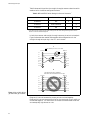
1
CentreCOM 3600 Series Hub/Repeaters and AT-S4 Firmware Module Network Operations Manual Copyright 1995 Allied Telesyn International All rights reserved. No part of this publication may be reproduced without prior written permission from Allied Telesyn International. Allied Telesyn International reserves the right to make changes in specifications and other information contained in this document without prior written notice. The information provided herein is subject to change without notice. In no event shall Allied Telesyn International be liable for any incidental, special, indirect, or consequential damages whatsoever, including but not limited to lost profits, arising out of or related to this manual or the information contained herein, even if Allied Telesyn International has been advised of, known, or should have known, the possibility of such damages. Ethernet is a registered trademark of Xerox Corporation. UNIX is a registered trademark of UNIX System Laboratories. Novell and NetWare are registered trademarks of Novell, Inc. Microsoft and MS-DOS are registered trademarks and LAN Manager and Windows for Workgroups are trademarks of Microsoft Corporation. 3Com is a registered trademark of 3Com. PC-NFS is a trademark of Sun Microsystems, Inc. PC/TCP is a registered trademark of FTP Software, Inc. DECnet is a registered trademark of Digital Equipment Corporation. Table of Contents Chapter 1 Overview . . . . . . . . . . . . . . . . . . . . . . . . . . . . . . . . . . . . . . . . . . . . . . . . . . . . . . . . . . . . . . . . . . . . . . . . . . . 1 CentreCOM AT-3600 Series Repeaters. . . . . . . . . . . . . . . . . . . . . . . . . . . . . . . . . . . . . . . . . . . . . . . . . . . . . . 1 Features . . . . . . . . . . . . . . . . . . . . . . . . . . . . . . . . . . . . . . . . . . . . . . . . . . . . . . . . . . . . . . . . . . . . . . . . . . . 2 Connectivity . . . . . . . . . . . . . . . . . . . . . . . . . . . . . . . . . . . . . . . . . . . . . . . . . . . . . . . . . . . . . . . . . . . . . . . 3 Wiring Configuration Rules . . . . . . . . . . . . . . . . . . . . . . . . . . . . . . . . . . . . . . . . . . . . . . . . . . . . . . . . . . . 3 Chassis Configuration . . . . . . . . . . . . . . . . . . . . . . . . . . . . . . . . . . . . . . . . . . . . . . . . . . . . . . . . . . . . . . . . . . . 4 Network Management . . . . . . . . . . . . . . . . . . . . . . . . . . . . . . . . . . . . . . . . . . . . . . . . . . . . . . . . . . . . . . . . . . . 5 Agent Software Upgrades . . . . . . . . . . . . . . . . . . . . . . . . . . . . . . . . . . . . . . . . . . . . . . . . . . . . . . . . . . . . . 5 Standard Agent Software . . . . . . . . . . . . . . . . . . . . . . . . . . . . . . . . . . . . . . . . . . . . . . . . . . . . . . . . . . . . . 5 Management Planning . . . . . . . . . . . . . . . . . . . . . . . . . . . . . . . . . . . . . . . . . . . . . . . . . . . . . . . . . . . . . . . 7 Local Hub Connection . . . . . . . . . . . . . . . . . . . . . . . . . . . . . . . . . . . . . . . . . . . . . . . . . . . . . . . . . . . . . . . . 7 Central-Site Connection . . . . . . . . . . . . . . . . . . . . . . . . . . . . . . . . . . . . . . . . . . . . . . . . . . . . . . . . . . . . . 10 Agent Software . . . . . . . . . . . . . . . . . . . . . . . . . . . . . . . . . . . . . . . . . . . . . . . . . . . . . . . . . . . . . . . . . . . . . . . . 11 AT-View . . . . . . . . . . . . . . . . . . . . . . . . . . . . . . . . . . . . . . . . . . . . . . . . . . . . . . . . . . . . . . . . . . . . . . . . . . 11 Boot Protocol (BootP) . . . . . . . . . . . . . . . . . . . . . . . . . . . . . . . . . . . . . . . . . . . . . . . . . . . . . . . . . . . . . . . 11 Trivial File Transfer Protocol (TFTP) . . . . . . . . . . . . . . . . . . . . . . . . . . . . . . . . . . . . . . . . . . . . . . . . . . 12 Contacting ATI Technical Support . . . . . . . . . . . . . . . . . . . . . . . . . . . . . . . . . . . . . . . . . . . . . . . . . . . . . . . . 13 Phone Numbers . . . . . . . . . . . . . . . . . . . . . . . . . . . . . . . . . . . . . . . . . . . . . . . . . . . . . . . . . . . . . . . . . . . . 13 Bulletin Board Services . . . . . . . . . . . . . . . . . . . . . . . . . . . . . . . . . . . . . . . . . . . . . . . . . . . . . . . . . . . . . 14 Internet Mail . . . . . . . . . . . . . . . . . . . . . . . . . . . . . . . . . . . . . . . . . . . . . . . . . . . . . . . . . . . . . . . . . . . . . . 14 CompuServe Forum . . . . . . . . . . . . . . . . . . . . . . . . . . . . . . . . . . . . . . . . . . . . . . . . . . . . . . . . . . . . . . . . 14 Related Documentation . . . . . . . . . . . . . . . . . . . . . . . . . . . . . . . . . . . . . . . . . . . . . . . . . . . . . . . . . . . . . . . . . 14 Chapter 2 Installation . . . . . . . . . . . . . . . . . . . . . . . . . . . . . . . . . . . . . . . . . . . . . . . . . . . . . . . . . . . . . . . . . . . . . . . . CentreCOM Multiport Hub . . . . . . . . . . . . . . . . . . . . . . . . . . . . . . . . . . . . . . . . . . . . . . . . . . . . . . . . . . . . . . Master Module . . . . . . . . . . . . . . . . . . . . . . . . . . . . . . . . . . . . . . . . . . . . . . . . . . . . . . . . . . . . . . . . . . . . Backup Module . . . . . . . . . . . . . . . . . . . . . . . . . . . . . . . . . . . . . . . . . . . . . . . . . . . . . . . . . . . . . . . . . . . . Software Installation . . . . . . . . . . . . . . . . . . . . . . . . . . . . . . . . . . . . . . . . . . . . . . . . . . . . . . . . . . . . . . . . . . . Updating Other Repeaters . . . . . . . . . . . . . . . . . . . . . . . . . . . . . . . . . . . . . . . . . . . . . . . . . . . . . . . . . . . The RS232 Management Port . . . . . . . . . . . . . . . . . . . . . . . . . . . . . . . . . . . . . . . . . . . . . . . . . . . . . . . . . . . . 15 15 15 15 16 18 19 iii Table of Contents Chapter 3 Repeater (Hub) Management . . . . . . . . . . . . . . . . . . . . . . . . . . . . . . . . . . . . . . . . . . . . . . . . . . . . . . . . .21 User Interface . . . . . . . . . . . . . . . . . . . . . . . . . . . . . . . . . . . . . . . . . . . . . . . . . . . . . . . . . . . . . . . . . . . . . . . . 21 Supported Terminals . . . . . . . . . . . . . . . . . . . . . . . . . . . . . . . . . . . . . . . . . . . . . . . . . . . . . . . . . . . . . . . . . . . 21 Statistics Database . . . . . . . . . . . . . . . . . . . . . . . . . . . . . . . . . . . . . . . . . . . . . . . . . . . . . . . . . . . . . . . . . . . . 23 Working with the Management Agent . . . . . . . . . . . . . . . . . . . . . . . . . . . . . . . . . . . . . . . . . . . . . . . . . . . . . 24 Starting a Session . . . . . . . . . . . . . . . . . . . . . . . . . . . . . . . . . . . . . . . . . . . . . . . . . . . . . . . . . . . . . . . . . .24 Selecting Menu Options . . . . . . . . . . . . . . . . . . . . . . . . . . . . . . . . . . . . . . . . . . . . . . . . . . . . . . . . . . . . . .25 Ending a Session . . . . . . . . . . . . . . . . . . . . . . . . . . . . . . . . . . . . . . . . . . . . . . . . . . . . . . . . . . . . . . . . . . .26 Chapter 4 Management Menus . . . . . . . . . . . . . . . . . . . . . . . . . . . . . . . . . . . . . . . . . . . . . . . . . . . . . . . . . . . . . . . . .27 Main Menu . . . . . . . . . . . . . . . . . . . . . . . . . . . . . . . . . . . . . . . . . . . . . . . . . . . . . . . . . . . . . . . . . . . . . . . . . . . 27 Port Status Menu. . . . . . . . . . . . . . . . . . . . . . . . . . . . . . . . . . . . . . . . . . . . . . . . . . . . . . . . . . . . . . . . . . . . . . 29 Link . . . . . . . . . . . . . . . . . . . . . . . . . . . . . . . . . . . . . . . . . . . . . . . . . . . . . . . . . . . . . . . . . . . . . . . . . . . . . .29 Status . . . . . . . . . . . . . . . . . . . . . . . . . . . . . . . . . . . . . . . . . . . . . . . . . . . . . . . . . . . . . . . . . . . . . . . . . . . .30 Polarity . . . . . . . . . . . . . . . . . . . . . . . . . . . . . . . . . . . . . . . . . . . . . . . . . . . . . . . . . . . . . . . . . . . . . . . . . . .30 Port Configuration Menu . . . . . . . . . . . . . . . . . . . . . . . . . . . . . . . . . . . . . . . . . . . . . . . . . . . . . . . . . . . . . . . 30 Current Status . . . . . . . . . . . . . . . . . . . . . . . . . . . . . . . . . . . . . . . . . . . . . . . . . . . . . . . . . . . . . . . . . . . . .31 Options . . . . . . . . . . . . . . . . . . . . . . . . . . . . . . . . . . . . . . . . . . . . . . . . . . . . . . . . . . . . . . . . . . . . . . . . . . .31 AUI Port . . . . . . . . . . . . . . . . . . . . . . . . . . . . . . . . . . . . . . . . . . . . . . . . . . . . . . . . . . . . . . . . . . . . . . . . . .32 Hub Statistics Menu . . . . . . . . . . . . . . . . . . . . . . . . . . . . . . . . . . . . . . . . . . . . . . . . . . . . . . . . . . . . . . . . . . . 33 Options . . . . . . . . . . . . . . . . . . . . . . . . . . . . . . . . . . . . . . . . . . . . . . . . . . . . . . . . . . . . . . . . . . . . . . . . . . .33 Hub Overview Graph . . . . . . . . . . . . . . . . . . . . . . . . . . . . . . . . . . . . . . . . . . . . . . . . . . . . . . . . . . . . . . . .34 Hub Statistics Counter Graphs . . . . . . . . . . . . . . . . . . . . . . . . . . . . . . . . . . . . . . . . . . . . . . . . . . . . . . . .34 Module Statistics Menu. . . . . . . . . . . . . . . . . . . . . . . . . . . . . . . . . . . . . . . . . . . . . . . . . . . . . . . . . . . . . . . . . 35 Options . . . . . . . . . . . . . . . . . . . . . . . . . . . . . . . . . . . . . . . . . . . . . . . . . . . . . . . . . . . . . . . . . . . . . . . . . . .35 Module Overview Graph . . . . . . . . . . . . . . . . . . . . . . . . . . . . . . . . . . . . . . . . . . . . . . . . . . . . . . . . . . . . .36 Module Statistics Counter Graph . . . . . . . . . . . . . . . . . . . . . . . . . . . . . . . . . . . . . . . . . . . . . . . . . . . . . .36 Individual Port Statistics . . . . . . . . . . . . . . . . . . . . . . . . . . . . . . . . . . . . . . . . . . . . . . . . . . . . . . . . . . . . .37 Administration Menu . . . . . . . . . . . . . . . . . . . . . . . . . . . . . . . . . . . . . . . . . . . . . . . . . . . . . . . . . . . . . . . . . . 38 Hub Name Menu . . . . . . . . . . . . . . . . . . . . . . . . . . . . . . . . . . . . . . . . . . . . . . . . . . . . . . . . . . . . . . . . . . . . . . 38 Module Name Menu . . . . . . . . . . . . . . . . . . . . . . . . . . . . . . . . . . . . . . . . . . . . . . . . . . . . . . . . . . . . . . . . . . . 39 Password, Timeout Menu . . . . . . . . . . . . . . . . . . . . . . . . . . . . . . . . . . . . . . . . . . . . . . . . . . . . . . . . . . . . . . . 39 Network Parameters Menu. . . . . . . . . . . . . . . . . . . . . . . . . . . . . . . . . . . . . . . . . . . . . . . . . . . . . . . . . . . . . . 40 Hub IP Address . . . . . . . . . . . . . . . . . . . . . . . . . . . . . . . . . . . . . . . . . . . . . . . . . . . . . . . . . . . . . . . . . . . .40 Subnet Mask . . . . . . . . . . . . . . . . . . . . . . . . . . . . . . . . . . . . . . . . . . . . . . . . . . . . . . . . . . . . . . . . . . . . . . .41 Gateway Address . . . . . . . . . . . . . . . . . . . . . . . . . . . . . . . . . . . . . . . . . . . . . . . . . . . . . . . . . . . . . . . . . . .41 SNMP Address . . . . . . . . . . . . . . . . . . . . . . . . . . . . . . . . . . . . . . . . . . . . . . . . . . . . . . . . . . . . . . . . . . . . .41 ‘Get’ Community String . . . . . . . . . . . . . . . . . . . . . . . . . . . . . . . . . . . . . . . . . . . . . . . . . . . . . . . . . . . . . .42 ‘Set’ Community String . . . . . . . . . . . . . . . . . . . . . . . . . . . . . . . . . . . . . . . . . . . . . . . . . . . . . . . . . . . . . .42 ‘Trap’ Community String . . . . . . . . . . . . . . . . . . . . . . . . . . . . . . . . . . . . . . . . . . . . . . . . . . . . . . . . . . . . .42 Download Password . . . . . . . . . . . . . . . . . . . . . . . . . . . . . . . . . . . . . . . . . . . . . . . . . . . . . . . . . . . . . . . . .43 Location String . . . . . . . . . . . . . . . . . . . . . . . . . . . . . . . . . . . . . . . . . . . . . . . . . . . . . . . . . . . . . . . . . . . . .43 Contact String . . . . . . . . . . . . . . . . . . . . . . . . . . . . . . . . . . . . . . . . . . . . . . . . . . . . . . . . . . . . . . . . . . . . .43 Terminal Configuration Menu . . . . . . . . . . . . . . . . . . . . . . . . . . . . . . . . . . . . . . . . . . . . . . . . . . . . . . . . . . . 44 Terminal Type . . . . . . . . . . . . . . . . . . . . . . . . . . . . . . . . . . . . . . . . . . . . . . . . . . . . . . . . . . . . . . . . . . . . .45 Custom Terminal Configuration . . . . . . . . . . . . . . . . . . . . . . . . . . . . . . . . . . . . . . . . . . . . . . . . . . . . . . .45 Data Rate . . . . . . . . . . . . . . . . . . . . . . . . . . . . . . . . . . . . . . . . . . . . . . . . . . . . . . . . . . . . . . . . . . . . . . . . .47 Language Menu . . . . . . . . . . . . . . . . . . . . . . . . . . . . . . . . . . . . . . . . . . . . . . . . . . . . . . . . . . . . . . . . . . . . . . . 48 iv Download Menus . . . . . . . . . . . . . . . . . . . . . . . . . . . . . . . . . . . . . . . . . . . . . . . . . . . . . . . . . . . . . . . . . . . . . . Update Selected Node . . . . . . . . . . . . . . . . . . . . . . . . . . . . . . . . . . . . . . . . . . . . . . . . . . . . . . . . . . . . . . . Download All Nodes . . . . . . . . . . . . . . . . . . . . . . . . . . . . . . . . . . . . . . . . . . . . . . . . . . . . . . . . . . . . . . . . Activity Monitor . . . . . . . . . . . . . . . . . . . . . . . . . . . . . . . . . . . . . . . . . . . . . . . . . . . . . . . . . . . . . . . . . . . . . . . EtherMeter . . . . . . . . . . . . . . . . . . . . . . . . . . . . . . . . . . . . . . . . . . . . . . . . . . . . . . . . . . . . . . . . . . . . . . . Diagnostics . . . . . . . . . . . . . . . . . . . . . . . . . . . . . . . . . . . . . . . . . . . . . . . . . . . . . . . . . . . . . . . . . . . . . . . Connect to a Remote Hub . . . . . . . . . . . . . . . . . . . . . . . . . . . . . . . . . . . . . . . . . . . . . . . . . . . . . . . . . . . . 50 50 50 50 52 53 53 Chapter 5 Fault Tolerance . . . . . . . . . . . . . . . . . . . . . . . . . . . . . . . . . . . . . . . . . . . . . . . . . . . . . . . . . . . . . . . . . . . . Department Concentrator Reconfiguration . . . . . . . . . . . . . . . . . . . . . . . . . . . . . . . . . . . . . . . . . . . . . . . . . Module Failures . . . . . . . . . . . . . . . . . . . . . . . . . . . . . . . . . . . . . . . . . . . . . . . . . . . . . . . . . . . . . . . . . . . . . . . Configuration Data. . . . . . . . . . . . . . . . . . . . . . . . . . . . . . . . . . . . . . . . . . . . . . . . . . . . . . . . . . . . . . . . . . . . . Precedence . . . . . . . . . . . . . . . . . . . . . . . . . . . . . . . . . . . . . . . . . . . . . . . . . . . . . . . . . . . . . . . . . . . . . . . . Voting . . . . . . . . . . . . . . . . . . . . . . . . . . . . . . . . . . . . . . . . . . . . . . . . . . . . . . . . . . . . . . . . . . . . . . . . . . . . Swapping Modules . . . . . . . . . . . . . . . . . . . . . . . . . . . . . . . . . . . . . . . . . . . . . . . . . . . . . . . . . . . . . . . . . 55 55 56 56 57 57 57 Chapter 6 SNMP Management . . . . . . . . . . . . . . . . . . . . . . . . . . . . . . . . . . . . . . . . . . . . . . . . . . . . . . . . . . . . . . . . . Overview . . . . . . . . . . . . . . . . . . . . . . . . . . . . . . . . . . . . . . . . . . . . . . . . . . . . . . . . . . . . . . . . . . . . . . . . . . . . . SNMP Commands . . . . . . . . . . . . . . . . . . . . . . . . . . . . . . . . . . . . . . . . . . . . . . . . . . . . . . . . . . . . . . . . . . . . . Management Information Base . . . . . . . . . . . . . . . . . . . . . . . . . . . . . . . . . . . . . . . . . . . . . . . . . . . . . . . . . . . AT-3600 Series Repeaters . . . . . . . . . . . . . . . . . . . . . . . . . . . . . . . . . . . . . . . . . . . . . . . . . . . . . . . . . . . 59 59 59 59 60 Appendix A Data Cabling Techniques . . . . . . . . . . . . . . . . . . . . . . . . . . . . . . . . . . . . . . . . . . . . . . . . . . . . . . . . . . . . 10BASE-T . . . . . . . . . . . . . . . . . . . . . . . . . . . . . . . . . . . . . . . . . . . . . . . . . . . . . . . . . . . . . . . . . . . . . . . . . . . . UTP Hub-to-MAU Wiring . . . . . . . . . . . . . . . . . . . . . . . . . . . . . . . . . . . . . . . . . . . . . . . . . . . . . . . . . . . . UTP MAU-to-MAU, Hub-to-Hub Wiring . . . . . . . . . . . . . . . . . . . . . . . . . . . . . . . . . . . . . . . . . . . . . . . . MDI/MDI-X Switch . . . . . . . . . . . . . . . . . . . . . . . . . . . . . . . . . . . . . . . . . . . . . . . . . . . . . . . . . . . . . . . . . 10BASE-FL/FOIRL Ethernet . . . . . . . . . . . . . . . . . . . . . . . . . . . . . . . . . . . . . . . . . . . . . . . . . . . . . . . . . . . . 10BASE5 (Thick) Ethernet . . . . . . . . . . . . . . . . . . . . . . . . . . . . . . . . . . . . . . . . . . . . . . . . . . . . . . . . . . . . . . AUI Drop Cables . . . . . . . . . . . . . . . . . . . . . . . . . . . . . . . . . . . . . . . . . . . . . . . . . . . . . . . . . . . . . . . . . . . 10BASE2 (Thin) Ethernet . . . . . . . . . . . . . . . . . . . . . . . . . . . . . . . . . . . . . . . . . . . . . . . . . . . . . . . . . . . . . . . 61 61 62 63 63 65 65 65 65 Appendix B Glossary . . . . . . . . . . . . . . . . . . . . . . . . . . . . . . . . . . . . . . . . . . . . . . . . . . . . . . . . . . . . . . . . . . . . . . . . . . . 67 Appendix C Technical Support Fax Order . . . . . . . . . . . . . . . . . . . . . . . . . . . . . . . . . . . . . . . . . . . . . . . . . . . . . . . . 73 Incident Summary . . . . . . . . . . . . . . . . . . . . . . . . . . . . . . . . . . . . . . . . . . . . . . . . . . . . . . . . . . . . . . . . . . . . . 73 Appendix D CentreCOM AT-3600 Network Operations Manual Feedback . . . . . . . . . . . . . . . . . . . . . . . . . . . . . . . . . 75 v Table of Contents Appendix E Index . . . . . . . . . . . . . . . . . . . . . . . . . . . . . . . . . . . . . . . . . . . . . . . . . . . . . . . . . . . . . . . . . . . . . . . . . . . . . . .77 Appendix F Where To Find Us . . . . . . . . . . . . . . . . . . . . . . . . . . . . . . . . . . . . . . . . . . . . . . . . . . . . . . . . . . . . . . . . . . .83 List of Figures Figure 1: AT-3612TR Front Panel . . . . . . . . . . . . . . . . . . . . . . . . . . . . . . . . . . . . . . . . . . . . . . . . . . . . . . . . . .2 Figure 2: Populated AT-C36RS8-0R0 Chassis . . . . . . . . . . . . . . . . . . . . . . . . . . . . . . . . . . . . . . . . . . . . . . . .4 Figure 3: AT-S4 Cassette . . . . . . . . . . . . . . . . . . . . . . . . . . . . . . . . . . . . . . . . . . . . . . . . . . . . . . . . . . . . . . . .16 Figure 4: Firmware Cassette Location . . . . . . . . . . . . . . . . . . . . . . . . . . . . . . . . . . . . . . . . . . . . . . . . . . . . .17 Figure 5: AT-3600 RS232 DCE Connections . . . . . . . . . . . . . . . . . . . . . . . . . . . . . . . . . . . . . . . . . . . . . . . . .19 Figure 6: 10BASE-T UTP Cabling Hub-to-MAU or NIC (Straight-Through) . . . . . . . . . . . . . . . . . . . . . . .62 Figure 7: RJ45 Cable . . . . . . . . . . . . . . . . . . . . . . . . . . . . . . . . . . . . . . . . . . . . . . . . . . . . . . . . . . . . . . . . . . .63 Figure 8: Hub-to-Hub or MAU-to-MAU Wiring . . . . . . . . . . . . . . . . . . . . . . . . . . . . . . . . . . . . . . . . . . . . . .63 Figure 9: Hub-to-MAU Wiring (A) Usable and (B) Unusable . . . . . . . . . . . . . . . . . . . . . . . . . . . . . . . . . . .64 List of Tables Table 1: Manageable AT-3600 Series Repeater Models . . . . . . . . . . . . . . . . . . . . . . . . . . . . . . . . . . . . . . . . .3 Table 2: RS232 Cable . . . . . . . . . . . . . . . . . . . . . . . . . . . . . . . . . . . . . . . . . . . . . . . . . . . . . . . . . . . . . . . . . . .19 Table 3: Required Terminal Control Characters . . . . . . . . . . . . . . . . . . . . . . . . . . . . . . . . . . . . . . . . . . . . .21 Table 4: Optional Terminal Control Sequences . . . . . . . . . . . . . . . . . . . . . . . . . . . . . . . . . . . . . . . . . . . . . .22 Table 5: Statistics Database Per-Port Counters . . . . . . . . . . . . . . . . . . . . . . . . . . . . . . . . . . . . . . . . . . . . . .23 Table 6: Statistic Database Hub-Wide Counters . . . . . . . . . . . . . . . . . . . . . . . . . . . . . . . . . . . . . . . . . . . . .24 Table 7: Usable and Unusable Twisted Pair Cable . . . . . . . . . . . . . . . . . . . . . . . . . . . . . . . . . . . . . . . . . . .62 Table 8: MDI and MDI-X Switch Settings for Common Connection1 . . . . . . . . . . . . . . . . . . . . . . . . . . . . .64 vi Chapter 1 Overview This manual describes the software installation and network management procedures for the AT-3600 series of independently manageable hub/repeater models. The AT-3600 series also includes “Slave” modules that are not manageable as standalone devices (the AT-3624TS and AT-3624TRS models) and a bridge module, the AT-3675. The AT-3675 model is shipped with its own manual and is not considered in this Network Operations Manual. This manual focuses on the independently manageable models, each of which can serve as the primary management (or “Master”) module for a department concentrator. These manageable repeaters are pre-configured with a network management agent and a port for firmware upgrades. The AT-3624TS and AT-3624TRS “Slave” models, however, can be managed only through a “Master” module housed in the same department concentrator chassis. In such a department concentrator chassis, the configuration, status and statistical information of Slave repeaters will appear on the network management displays and can be manipulated in the same way as the data from the manageable modules. Note This manual refers to two or more chassis-mounted repeaters as a department concentrator. The term hub refers to either a standalone repeater or a department concentrator configuration. For information on the hardware installation and connectivity aspects of manageable AT-3600 Series Repeaters, see the separate CentreCOM 3600 Series Hub/Repeaters Installation Manual shipped with each repeater. CentreCOM AT-3600 Series Repeaters The CentreCOM AT-3600 Series is a set of multiple-port hub/repeaters designed to offer maximum flexibility and redundancy for both workgroup and department needs. They are IEEE 802.3 compliant/Ethernet compatible and support Simple Network Management Protocol (SNMP) with both the second version of the Management Information Base (MIB II) and Repeater MIB (also known as Hub MIB). 1 Overview Each manageable AT-3600 Series Repeater is a single building block for both standalone (repeater) and chassis (department concentrator) configurations. Allied Telesyn International (ATI) supplies desktop and rackmount department concentrator chassis that can hold up to eight AT-3600 Series Repeaters. Since the department concentrator chassis connects repeater modules across a backplane, a fully populated department concentrator behaves as a single repeater in the network topology. This enables you to build and reconfigure networks easily, efficiently and at minimum expense. Features AT-3600 Series Repeaters are based on an Application-Specific Integrated Circuit (ASIC) ATI developed for maximum functionality and reliability. Figure 1 shows a sample AT-3600 Series Repeater faceplate, in this case the front panel of an AT-3612TR. PORT ACTIVITY 10 BASE T NETWORK PORTS PORT STATUS 1 2 3 4 5 6 7 8 9 10 11 12 No Link Link Receiving 1 2 3 4 5 6 7 8 INDICATOR STATUS Indicator OFF Indicator ON Indicator FLASHING LINK RS-232 TERMINAL PORT STATUS POWER CentreCOM 3612TR TM 2 4 6 8 10 12 10 BASE-T FAULT MASTER IEEE 802.3/ETHERNET 10BASE2 MULTIPORT HUB / REPEATER with Network Management POWER X X X X X X X X X X X X 1 3 5 7 9 11 APPLIQUÉ PORT Figure 1: AT-3612TR Front Panel Each manageable AT-3600 Series Repeater is self-contained and provides the following standard features regardless of the media type or number of ports: ❑ ❑ ❑ ❑ ❑ ❑ ❑ ❑ 2 Internal universal power supply IEEE 802.3 compliance; Ethernet Version 1.0 and 2.0 compatible repeater functionality Appliqué port supports optional transceiver modules for backbone or interrepeater connectivity: — Unshielded Twisted Pair (UTP) (10BASE-T) — Thinnet (10BASE2) — Attachment Unit Interface (AUI) (10BASE5) — Fiber optic (Fiber Optic Inter-Repeater Link [FOIRL], 10BASE-FL) Placement options include standalone, 19-inch rack mount or chassis mount Three types of network management capability: — SNMP — Via ASYNC ASCII terminal port (Omega) — Telnet (Omega) Software upgrade through firmware cassette or in-band downloading Hot swapping of modules in chassis Comprehensive diagnostic LED support CentreCOM 3600 Series Hub/Repeaters Connectivity Table 1 shows the various models of manageable AT-3600 Series Repeaters. You can mix any combination of model types in a department concentrator chassis for maximum flexibility. Table 1: Manageable AT-3600 Series Repeater Models Note Model Number Port Count Media/Connector Type AT-3606F 6 Fiber Optic (FOIRL, 10BASE-FL) with Straight Tip (ST) Connectors AT-3606F/SMA 6 Fiber Optic (FOIRL, 10BASE-FL) with Sub Miniature Assembly (SMA) connectors AT-3608 8 Thinnet (10BASE2) with Bayonet Nut Couple (BNC) connectors AT-3612T 12 UTP (10BASE-T) with Telco 50-pin (RJ21) connector AT-3612TR 12 UTP (10BASE-T) with RJ45 connectors AT-3624T 24 UTP (10BASE-T) with 2 Telco 50-pin (RJ21) connectors AT-3624TR 24 UTP (10BASE-T) with RJ45 connectors References in this manual to SMA and SM are interchangeable, both being acronyms for Sub Miniature Assembly. For descriptions of individual model types, including faceplate design, connection type and LED displays, see CentreCOM 3600 Series Hub/ Repeaters Installation Manual. Wiring Configuration Rules Depending on the medium you choose, there are certain wiring practices you should follow to ensure the reliability of communication throughout the network. The AT-3600 Series complies with IEEE standards for 802.3 Carrier-Sense Multiple-Access with Collision Detection (CSMA/CD) Ethernet; you should refer to these standards when implementing your network. Some important guidelines for ensuring integrity in network wiring appear in CentreCOM 3600 Series Hub/Repeaters Installation Manual. 3 Overview Chassis Configuration You can use a single manageable AT-3600 Series Repeater in standalone mode or as part of a department concentrator housed in a chassis. Various chassis models are available for desktop or rackmount configurations. These include 1-, 2-, 3-, 4-, 7-, and 8-module combinations for desktop or 19-inch rackmount installations with standard or fragmented backplanes. These chassis address a range of needs for different sized networks and uses. Call your ATI sales representative for details. Figure 2 shows a sample department concentrator using an AT-C36RS8-0R0 Chassis. You can configure up to eight AT-3600 Series Repeaters in this rackmount model. When fully populated with manageable AT-3600 Series Repeaters, the AT-C36RS8-0R0 creates a single department concentrator with 200 ports (8 modules with 24 network ports each, plus 8 AUI ports). FOIRL NETWORK PORTS 1-6 RS-232 TERMINAL PORT 1 2 3 4 5 6 ON LINE ON LINE ON LINE ON LINE ON LINE ON LINE POWER STATUS CentreCOM 3606F TM FAULT AUI IEEE 802.3/ETHERNET FOIRL MULTIPORT HUB / REPEATER with Network Management MASTER TX RX TX RX RECEIVE TX RECEIVE RX TX RECEIVE RX TX RX RECEIVE TX RECEIVE POWER RX RECEIVE APPLIQUÉ PORT FOIRL NETWORK PORTS 1-6 1 2 ON LINE 3 ON LINE RS-232 TERMINAL PORT 4 ON LINE 5 ON LINE POWER STATUS 6 ON LINE CentreCOM 3606F TM ON LINE FAULT AUI IEEE 802.3/ETHERNET FOIRL MULTIPORT HUB / REPEATER with Network Management MASTER TX RX TX RX RECEIVE TX RECEIVE RX TX RECEIVE RX TX RX RECEIVE TX RECEIVE POWER RX RECEIVE APPLIQUÉ PORT FOIRL NETWORK PORTS 1-8 1 2 3 4 RS-232 TERMINAL PORT 5 6 7 POWER STATUS 8 ON LINE ON LINE ON LINE ON LINE ON LINE ON LINE ON LINE ON LINE ON ON ON ON ON ON ON ON CentreCOM 3608 TM FAULT AUI IEEE 802.3/ETHERNET 10BASE2 MULTIPORT HUB / REPEATER with Network Management MASTER OFF OFF OFF OFF OFF OFF OFF OFF TERMINATOR TERMINATOR TERMINATOR TERMINATOR TERMINATOR TERMINATOR TERMINATOR TERMINATOR RECEIVE RECEIVE RECEIVE RECEIVE RECEIVE RECEIVE RECEIVE POWER RECEIVE APPLIQUÉ PORT FOIRL NETWORK PORTS 1-8 1 2 ON LINE 3 ON LINE ON 4 RS-232 TERMINAL PORT 5 ON LINE ON ON LINE ON 6 7 ON LINE ON ON LINE ON POWER STATUS 8 ON LINE ON ON LINE ON CentreCOM 3608 TM ON FAULT AUI IEEE 802.3/ETHERNET 10BASE2 MULTIPORT HUB / REPEATER with Network Management MASTER OFF OFF OFF OFF OFF OFF OFF OFF TERMINATOR TERMINATOR TERMINATOR TERMINATOR TERMINATOR TERMINATOR TERMINATOR TERMINATOR RECEIVE RECEIVE RECEIVE RECEIVE RECEIVE RECEIVE RECEIVE POWER RECEIVE APPLIQUÉ PORT PORT ACTIVITY 10 BASE T NETWORK PORTS 1-12 PORT STATUS No Link Link Receiving STATUS P O W E R COLLISION MASTER 2 4 INDICATOR STATUS Indicator OFF Indicator ON Indicator FLASHING 6 8 RS-232 TERMINAL PORT LINK 10 TM POWER 1 3 5 7 9 11 APPLIQUÉ PORT PORT ACTIVITY 10 BASE T NETWORK PORTS 1-12 PORT STATUS No Link Link Receiving STATUS P O W E R COLLISION MASTER 2 4 INDICATOR STATUS Indicator OFF Indicator ON Indicator FLASHING 6 8 RS-232 TERMINAL PORT LINK 10 TM POWER 1 3 5 7 7 9 11 APPLIQUÉ PORT PORT ACTIVITY PORT STATUS 6 8 IEEE 802.3/ETHERNET 10BASE2 MULTIPORT HUB / REPEATER with Network Management MASTER 10 BASE T NETWORK PORTS 5 CentreCOM 3612T FAULT FOIRL ACTIVITY 4 POWER STATUS 12 FAULT 3 IEEE 802.3/ETHERNET 10BASE2 MULTIPORT HUB / REPEATER with Network Management MASTER ACTIVITY 2 CentreCOM 3612T FAULT FOIRL FAULT 1 POWER STATUS 12 9 10 11 No Link Link Receiving 12 1 2 3 4 5 6 7 RS-232 TERMINAL PORT 8 INDICATOR STATUS LINK Indicator OFF Indicator ON Indicator FLASHING POWER STATUS CentreCOM 3612TR TM 2 4 6 8 10 12 FAULT 10 BASE-T IEEE 802.3/ETHERNET 10BASE2 MULTIPORT HUB / REPEATER with Network Management MASTER POWER TM Figure 2: Populated AT-C36RS8-0R0 Chassis X X X X X X X X X X 1 X 3 5 7 9 11 APPLIQUÉ PORT 10 BASE-T NETWORK PORTS PORT ACTIVITY IEEE 802.3/ETHERNET 10 BASE-T 24 PORT HUB / REPEATER CentreCOM 3624TRS X 1 2 PORT STATUS 3 4 INDICATOR STATUS 5 NO LINK 6 7 INDICATOR OFF 8 LINK 9 10 INDICATOR ON GREEN 11 12 RECEIVING 13 STATUS INDICATOR FLASHING GREEN 14 15 16 PARTITIONED 17 18 INDICATOR ON AMBER 19 COLLISION 20 21 POWER INDICATOR FLASHING AMBER 22 23 24 FAULT ACTIVITY POWER X X X X X X X X X X X X X X X X X X X X X X X X You can mount all or any combination of the following Repeater models in the same department concentrator chassis: AT-3606F, AT-3606F/SMA, AT-3606F/ ST, AT-3606F/SC, AT-3608, AT-3612T, AT-3612TR, AT-3624T and AT-3624TR. Network management software will view the concentrator as a single device. Not all slots have to be populated, and populated slots do not have to be contiguous. You can also combine manageable with non-manageable modules (AT-3612FS, AT-3624TS and AT-3624TRS) in the same concentrator. However, each chassis must contain at least one manageable repeater module in the upper-most slots to enable management of all repeaters in the chassis. 4 CentreCOM 3600 Series Hub/Repeaters Network Management All manageable CentreCOM AT-3600 Series Repeaters are equipped with network management agents. In a standalone configuration, the agent makes the repeater a manageable node (or hub) on the network. In a department concentrator, the Master module provides agent services for the entire concentrator. Should the Master module fail, the Backup takes over the Master functions automatically. You can hot swap any module other than the Master to trace faults or reconfigure the concentrator without network downtime. Refer to Chapter 2 on page 15 for information on configuring concentrators and Chapter 5 on page 55 for information on failure recovery. Network management support is provided through an RS232 terminal port (the Omega Agent) and through a Telnet session (to the Omega Agent) for inexpensive local management. The SNMP agent also supports industry-standard SNMP Network Management Stations. Agent Software Upgrades The AT-3600 agent software is easy to upgrade through the firmware cassette port. When you insert an optional AT-S4 firmware cassette into this port, the new firmware is copied to the repeater’s onboard non-volatile flash memory at power-up. Refer to Chapter 2 for information on AT-S4 capabilities and installation. Standard Agent Software Standard agent network management software includes: ❑ ❑ ❑ ❑ ❑ SNMP Management Information Base II (MIB II) Repeater MIB Out-of-band ASYNC ASCII terminal port (Omega) Remote network monitoring (Telnet) management (RFC 854) SNMP. SNMP, a component of the TCP/IP protocol suite, includes only three commands: GET, GET NEXT and SET. These simple commands are executed against a lengthy list of variables (or managed objects), called the Management Information Base (MIB), within the repeater itself. Should the Master (or top unit in the chassis) fail, the Backup (or second from the top unit) automatically takes over all Master functions. You can hot swap any module other than the active Master to trace faults or reconfigure the concentrator without interrupting hub management functions. ❑ ❑ ❑ A limited set of management operations Definitions of manageable variables Data representations SNMP has three fundamental operations which are, in turn, applied to network parameters such as statistical counters and status indicators: ❑ ❑ ❑ Get: retrieves a variable and the command GetNext: retrieve the next, or entire, variable Set: a command that writes values into a variable 5 Overview These three commands are executed against a lengthy list of variables (or managed objects) contained in either MIB II or the Repeater MIB. For example, TCP/IP and SNMP network parameters include: Repeater IP address, Subnet mask, Gateway address, SNMP manager address, ‘Trap’ community string, ‘Location’ string and ‘Contact’ string Omega. Omega is a term used by ATI to designate the network management agent contained in the AT-3600 Management Module. Omega enables network management either locally through an RS232 terminal port or remotely through a Telnet session. The Omega agent also supports industry-standard SNMP Network Management Stations Omega software (as well as SNMP) is pre-loaded into the Flash EPROM of each AT-3600 manager hub. Omega allows two interconnected AT-3600 Series repeaters to be managed locally through the use of an out-of-band ASCII terminal. Two interconnected AT-3600 Series repeaters can also be managed through a remote Omega session (Omega includes Telnet). In short, Omega provides inexpensive local network management through the ASCII terminal connected to the RS232C (ASYNC) Management Module Bus port. A discussion of the RS232C (ASYNC) Management Module Bus port follows the discussion of Omega. Omega supports the following: ❑ ❑ ❑ ❑ ❑ ❑ ❑ Statistics Internal self diagnostics Setting TCP/IP parameters Port status indications Control of software downloading functions Connection to a remote repeater Naming of repeaters, groups and ports As noted above, Omega provides exactly the same user interface regardless of whether the terminal is connected directly (via the RS232C port) or through the network (using the integrated Telnet feature which is incorporated into Omega). Omega/Telnet is transparent to the user when the “Connect to a remote hub” function on the Administration Screen is used. In this case, both sides of the network should have the same capability (e.g., the network management node as well as the repeater should have either Omega or Telnet). This option initiates an outbound session to any ATI repeater and is particularly useful when you are managing a network from a remote site. An additional benefit of Omega is that it enables ATI technical support technicians to view a customers’ network for diagnostic purposes using Internet. 6 CentreCOM 3600 Series Hub/Repeaters Management Planning Before installing and connecting manageable AT-3600 Series Repeaters at various site locations (such as in closets in a single building or in closets on different floors or in different buildings), you need to decide on the number of hubs in your network and where each hub is to be located. This advanced planning will facilitate the assignment of hub names, MAC and/or IP addresses. It will also maximize the efficiency of network management once your hubs are fully installed and operational. If you have a limited number of workgroup terminals and/or devices colocated on the same floor, for example, you may decide to manage each hub locally in a standalone configuration. In this scenario, a non-TCP network may be appropriate. If you have many geographically dispersed subnetworks, each connected to its own department concentrator, management of these multiple hubs remotely in a central-site configuration will require TCP/IP network management. Any manageable AT-3600 Series Repeater can be configured for local or central-site management. The Omega agent allows local hub management through the front console serial port connected directly to a terminal or PC. To enable central-site management of multiple hubs, the Omega agent requires that a TCP/IP address be installed in each hub. To enable hub management through the Omega “Connect to a remote hub” option, you will need to choose one of the following: ❑ ❑ Note Local Hub Connection For a non-TCP/IP network, each hub may be assigned a hub name; or each hub may be managed through its pre-assigned MAC address. For a TCP/IP network, every hub must have an assigned IP address or, as an option, a hub name. In a department concentrator configuration, where all the manageable repeaters share a common chassis and backplane, only the top (or Master) module needs to have TCP/IP address installed. The Omega management agent views the department concentrator as a single hub within a TCP/IP network. Local connection for a standalone configuration involves seven preliminary set-up steps: 1. Connect one end of a power cable into your power source. Connect the other end into the receptacle on the far right front panel of the 3600 Series unit. The front console Power Status light will illuminate and the unit will emit a soft humming sound. Your AT-3600 repeater is now functioning. 2. Connect the serial port of your terminal or PC to the RS232 console port on the front of the repeater. For a PC connection, use a straight-through 9-pin cable. 7 Overview 3. Turn on your terminal or PC and call up the terminal emulator program. Check your screen display to be sure the configuration options are set as follows: ❑ ❑ ❑ ❑ Data bits: 8 Stop bits: 1 Parity: 0 Connector: Com1/Com2 (PC/terminal dependent) The Omega program supports autobaud, so baud rate does not need to be configured on the terminal side. These configuration options apply whether you are using Windows or a DOS-based terminal emulator program. To be sure these options are always available, save them as an Omega file (i.e., omega.trm). Note 4. To activate the program, press the <return> key several times. This will ensure configuration of the appropriate baud rate. The Main Menu of the Omega local management program will appear on your screen, as follows: Allied Telesyn International AT-3606F Extendable Hub Sunnyvale Please select an option: Port status Hub Statistics Individual port overview Administration Quit -> Attention 8 Always be sure you are using a full screen at your terminal or PC. Otherwise, you may not see all the characters and menu items displayed by the Omega agent. CentreCOM 3600 Series Hub/Repeaters 5. Enter the letter A to access the Administration submenu: Sunnyvale Main Please select an option: Hub name Module name Password, timeout Network parameters Terminal configuration Language/langue/idioma/linguaggio/sprache Send updated software to another hub Update software in all hubs Activity monitor EtherMeter Diagnostics Connect to a remote hub -> 6. Enter the letter H for “Hub name”; this entry will call up the following submenu: Sunnyvale Main The Hub’s current name is: Sunnyvale Main Please enter a new name, or Return to retain the existing name: -> 7. Note At the screen prompt, enter hub name. Then, press <Return> to save the hub name. In selecting an option from most software program menus, you may use either capital or lower case letters. Usually the first letter of the first word in a menu option will be all that is required to call up a submenu. 9 Overview 8. For a TCP/IP network, enter N to call up the Network Parameters menu. This menu will lead you through a series of screens, each of which will ask you to enter values for such items as: Hub IP address, Subnet mask and Gateway address. Once you have assigned a hub name, MAC or IP address through the front console serial port connection, you will be able to use the Omega hub management program to: ❑ ❑ ❑ ❑ ❑ View statistics (on the entire hub or on individual ports) Disable/enable ports Name ports Configure network parameters Run diagnostics To enable local connection to multiple hubs in a non-TCP LAN, you must first assign a name to each hub connected to the LAN. You do this by calling up the Administration menu from the Omega agent Main Menu and selecting the “Connect to a remote hub” option. This option allows you to connect to any attached remote hub that has an Ethernet (MAC) address and thus also allows you to assign a unique name to any LAN-connected hub. Note In a non-TCP network, you cannot connect to a remote hub across network routers. To enable local connection to multiple hubs in a TCP/IP LAN, you must first assign an IP address to every LAN-connected hub. Once the IP addresses have been assigned, the Telnet application allows access to the local Omega program from anywhere in that network. The following procedures will enable remote hub management across a WAN: ❑ ❑ ❑ Central-Site Connection Connect a modem to the remote hub’s serial port, providing access to the Omega hub management program Call up the Administration menu from the Omega agent Main Menu Select the “Connect to a remote hub” option (This option also allows TCP connection to a remote hub provided the target hub has an IP address.) To enable central-site connection and network management, every hub in a TCP network must have an installed TCP/IP address. You can install a TCP/ IP address either by connecting to the serial port of a hub and bringing up the Omega local management program or by using a Bootp server. The “Network parameters” option (n) in the Omega Administration menu allows you to configure IP and SNMP information for the hubs in a TCP/IP network. This menu leads you through a series of configuration screens detailed in the CentreCOM 3600 Series and AT-S4 Firmware Module Network Operations Manual. 10 CentreCOM 3600 Series Hub/Repeaters Agent Software AT-View In addition to the Omega agent, ATI also provides an optional network management package called AT-View. This Windows-and/or UNIX-based SNMP software application offers an easy-to-use and inexpensive graphical user interface (GUI). AT-View is ideal for simple and fast diagnostics, as well as for configuration and the monitoring of network devices. Specifically, AT-View allows you to perform such network monitoring and management tasks as: ❑ ❑ ❑ ❑ ❑ ❑ Assign names to hubs, modules, and/or ports Identify enabled/disabled ports Change the enabled/disabled status of ports Configure polarity correction Set reconnect algorithms Enable/disable link test AT-View provides the tools to monitor your network’s health by tracking 20 current network statistics, including total collisions and errors. AT-View’s GUI toolkit also offers critical parameter graphing capability that facilitate the tracking of network performance trend lines. Boot Protocol (BootP) BootP is a protocol utility designed to automatically detect and recognize diskless workstations. The function of the BootP utility within an IP server is to enter an IP address into the repeater. That is, since all SNMP devices require an IP address if they are to be managed, environments that do not have BootP require you to enter the IP address manually. BootP is covered under RFC 951 and includes the following requirement: “In the case of clients who do not know their IP addresses, the server must also have a database relating hardware addresses to IP addresses. This client IP address is then placed into a field in the boot reply.” This RFC as well as other related RFC’s can be found on the anonymous FTP server NIS.NSF.NET in ATI’s documents\rfc directory. The options for configuring an IP address are Omega and BootP. With Omega, the unit will not send BootP requests once the unit has the IP address configured. The process is straightforward. If an IP address has NOT been configured for a unit (for example, if Omega was used through the console port), then the system will transmit a BootP request packet approximately every three seconds until a response is received (up to a maximum of three request attempts). If a BootP response is NOT received, the system will continue to operate with either the configured IP address, if an IP address was configured, or with a computed pseudo IP address (if an IP address was not configured). A pseudo IP address — a computed number based on the unit’s MAC address — allows the system to be managed in non-IP networks (e.g., Novell) without requiring you to either know or maintain an IP address. 11 Overview If a BootP response is received, then the IP address, Subnet Mask, and/or Gateway/Router address will be extracted from the response packet and used to configure the system until the next power-on/reset. Additionally, if the response packet specifies a filename and a TFTP host address, then a TFTP ‘get’ request will be sent to the specified host, using the specified filename. This will initiate a TFTP download of operating software and allows you to maintain downloaded server software. While the BootP server file format differs from server to server, most repeaters expect a packet containing an IP address, a Subnet Mask, and/or router address. Two files need to be configured to initiate BootP: 1. /etc/bootptab. This file contains the entries for each device wants to be booted when it is powered up. 2. /etc/services. This file contains the entries for all the services on the server. Once BootP service is requested, the entries for it should be entered as: 1. bootps 67/udp # bootstrap protocol server 2. bootpc 68/udp # bootstrap protocol client Once you have these files, BootP should be initialized when the server reboots. Below is an example from Allied Telesyn’s SUN system ‘bootptab’ file which is used to load an IP address between one of our bridges and one of our repeaters. bridge:ht=ethernet:ha=0000F4800a:ip=149.35.1.254:sm=255.255.255.0 repeater1:ht=ethernet:ha=0000F46541:ip=149.35.17.7:sm=255.255.255.0 Trivial File Transfer Protocol (TFTP) TFTP lets you transfer files between TCP/IP devices (hosts). You can use TFTP for simple file transfer sessions to transfer files without having to log into remote hosts and to transfer bootable files to or from a host. TFTP requires very little memory. The initial procedures for using TFTP to download/upload the AT-S4/S5 software operating image file for AT-3600 series managed hubs is as follows: ❑ ❑ ❑ ❑ ❑ 12 Be sure the TFTP program (from a TCP vendor such as Wollongong, FTP or NetManage) is installed in your work station Decide whether you are going to receive (“get”) the file from or send (“Put”) the file to a remote host Know the IP address of the remote host (i.e., the AT-3600/3100 series hub) Know the local filename (create one or use the image.S4 or image.S5) Know the transfer mode for the file (i.e., ASCII or octal for image files) CentreCOM 3600 Series Hub/Repeaters The general form of the TFTP command line is: tftp direction localfile hostIP hostfile mode The meaning of each command line item is as follows: ❑ ❑ ❑ ❑ ❑ ❑ tftp: starts the TFTP program direction: either “put” or “get” localfile: the IP address of the AT-3600 series managed hub hostIP: the IP address of the AT-3600 series managed hub hostfile: the name of the remote host (or, in the case of ATI, the remote host password) mode: the transfer mode for the file The command line you use to receive (“get”) the current download file from an AT-3600 series managed hub is as follows: tftp get image.s4 149.35.16.44 AT3600 octet You follow the same procedure to send (“put”) a file on a managed AT-3600 series managed hub. Contacting ATI Technical Support Problems? You can contact ATI’s Technical Support staff by: ❑ ❑ ❑ ❑ Telephone Bulletin board services Electronic mail via the Internet CompuServe forum When you contact Technical Support, you should have the following information available: ❑ ❑ ❑ Phone Numbers Serial number of your AT-4016TR Power-up test codes, if any Diagnostic test codes, if any Commercial telephone service is available Monday through Friday from 6:30 AM to 5:00 PM PST: 1-800-428-4835 (United States) The FAX number is: 206-481-3790 For telephone numbers outside of the United States and Canada, contact your reseller or regional ATI office. 13 Overview Bulletin Board Services A bulletin board is available. The number is: 206-483-7979 Modem settings are: 9600 baud; 8 bits; no parity; 1 stop bit. Internet Mail You can send electronic mail via the Internet to: [email protected] CompuServe Forum ATI has a forum on CompuServe. You can reach us by typing GO ALLIED at the CompuServe prompt (!). Related Documentation You may find the following networking reference material helpful: ❑ ❑ ❑ ❑ ❑ Interconnections, Bridges and Routers, Radia Perlman, Addison Wesley © 1992. Internetworking with TCP/IP: Principles, Protocols, and Architecture (2nd edition), Volumes I and II, Douglas Comer, Prentice Hall © 1991. The Simple Book, An Introduction to Management of TCP/IP-based Internets, Marshall T. Rose, Prentice Hall © Second Edition, 1994. Internet RFCs can be obtained through anonymous FTP or e-mail to [email protected] with the message: help: ways_to_get_rfcs Internet drafts are available by anonymous FTP. Internet draft directories are located at: — US East Coast: ds.internic.net — US West Coast: ftp.isi.edu — Europe: nic.nordu.net — Pacific Rim: nunnari.oz.au For further information on AT-3600 Series Hub/Repeater capabilities and installation, see CentreCOM 3600 Series Installation Manual. 14 Chapter 2 Installation CentreCOM Multiport Hub AT-3600 Series Repeaters act as IEEE 802.3 compliant Ethernet compatible installations. They support multiple stations on the network and have an additional network port for an AUI or other media appliqué to enable connection to the network’s main Ethernet backbone. An RS232 port allows connection to an asynchronous terminal or PC with terminal emulation for hub management. Each repeater also provides an interface to the Ethernet network that supports TCP/IP, SNMP and related protocols. The Omega software enables loading software updates across the network. The model AT-S4 Firmware Cassette is available for installing software backups and updates. AT-3600 Series Repeaters also implement an interprocessor interface that allows up to 8 repeaters to be cascaded together in a single department concentrator chassis. When operating in such a multiprocessor configuration, the management agent software manages all modules in the chassis. For the purposes of network topology analysis, all repeater modules combined in a department concentrator chassis collectively count as just one repeater. Master Module The uppermost manageable AT-3600 module in a chassis performs all management reporting activities and is referred to as the Master. The other AT-3600 modules in the same chassis are called Slaves. Modules are numbered from 1 through 8, top to bottom, in the chassis. The Master is defined as the module in the lowest-numbered (physically topmost) occupied slot position. Typically this is slot 1, but it could be slot 2 if slot 1 is vacant. Slave modules may occupy any other higher-numbered (physically lower) slot position. Such Slave modules do not need to be in contiguous slots because they are managed through a backplane that extends the full height of the chassis. Backup Module The next manageable module in the chassis communicates with the Master and can take over the Master’s functions if necessary. This special module is called the Backup and always occupies the next higher-numbered slot position in the chassis (i.e., physically below the Master). 15 Installation The management agent actually resides in every AT-3600 module, except the AT-3612FS, AT-3624TS/AT-3624TRS. These three models are configured as Slaves and can never serve as Master or Backup modules. The agent in the Master is active and available for use. The agent in the Backup remains inactive unless the Master fails. Refer to Chapter 5 on page 55 for further information on backup management and fault tolerance. Software Installation The Omega firmware is pre-loaded in manageable AT-3600 modules at the factory and is ready to use. An AT-S4 cassette is also available separately for backup and downloading to older AT-3600 Series Repeaters (see Figure 3). Figure 3: AT-S4 Cassette Note All hubs on your network should be running the same version of software. If, for example, you are installing a new standalone repeater into a network that has older AT-3600 modules running an earlier software version, you should update the other hubs to the latest version. You can use this compact cassette, similar to a cassette/cartridge used in laser printers and other devices, to override the login options for password protection and menu language. The firmware cassette includes network management agent software for any manageable AT-3600 module: ❑ ❑ ❑ ❑ ❑ Note 16 SNMP Agent supporting MIB II and Hub/Repeater MIB Omega Management Software Agent with menus in: English French German Spanish Italian Japanese (Kanji—requires use of Kanji async terminal or PC) Unlimited site license Software downloading capability (receive and transmit) Omega Telnet Network Management Software Agent-multilingual When upgrading management software on a network, first install the firmware cassette into a standalone repeater, upload the software, and then download to all repeaters and concentrators from this first repeater. CentreCOM 3600 Series Hub/Repeaters To reinstall or update the management agent Note 1. If you are loading software in a single standalone repeater, turn off the power for the repeater and skip to step 3. 2. If you are loading the software to a hub consisting of multiple modules in a department concentrator chassis, remove the Master from the chassis. When removing the department concentrator Master, always disengage the Master from the chassis backplane before unplugging the power cord; i.e., use the hot swapping method. Refer to your chassis user manual for more information. With the Master removed from the chassis, consider the repeater to be standalone for the purposes of steps 3 through 7. Attention Be sure to unplug the repeater’s power cord when installing and removing the firmware cassette. 3. Remove the blank cover plate from the Firmware Cassette slot on the back panel (see Figure 4). Unscrew the thumbscrews and slide out the blank plate by grasping the loosened thumbscrews. TM CentreCOM3606F FIRMWARE CASSETTE INTERREPEATER BUS IEEE 802.3 / ETHERNET 10BASE-FL/FOIRL 6 PORT HUB / REPEATER with Network Management STATUS POWER FIRMWARE CASSETTE MASTER FAULT Thumbscrews (2) Figure 4: Firmware Cassette Location Note 4. Slide the firmware cassette into the port; firmly press the connector housing into place and tighten the thumbscrews. The firmware cassette backing plate should be flush with the repeater panel. 5. Plug the power cord into the repeater. Downloading will proceed, taking up to two minutes. The repeater’s front panel LEDs flash continuously during downloading. The fault LED flashes once at the end of the download process. 6. Unplug the repeater and remove the software cassette. You may leave the cassette installed. If you do, however, the module will not be able to receive downloads over the network. This is so because the software network download will not overwrite a cassette. Moreover, password protection is disabled when the cassette is installed. 17 Installation 7. For a standalone repeater, the software installation is complete. 8. For a department concentrator Master, plug in the Master’s power cord and return Master to the chassis. The other modules in the chassis will then be automatically upgraded from the Master with no impact to the users on those modules. In a multi-module department concentrator, the Master controls software distribution to all of the Slaves within the same chassis. Inserting a software cassette into the Master and powering up each module will copy the cassette software into the non-volatile memory of each module in the chassis. Later, even if you’ve removed the cassette, a new Slave inserted into the chassis will also be loaded with the same software. This ensures that all modules are running the same version of software and eliminates any possibility of incompatibility between different software releases. Note Updating Other Repeaters If new software is loaded into any module other than the Master, the new software will be overwritten by the Master at power-up. The Omega software site license permits you to update other AT-3600 Series Repeaters through the network. You don’t need to insert an AT-S4 cassette in each repeater in the network or rack. The Omega user interface provides commands to load software into any other specified AT-3600 or to update all AT-3600 modules in the network. To update software, you must insert the new release cassette into one AT-3600 Master: from that Master module you can load the new software into other selected AT-3600 Series Repeaters. If you want, you can run the new software on a limited number of hubs as a kind of “dry run.” When you have become familiar with the new release, you can load it from one of the Masters to all other modules in the network. You can identify an individual repeater to be updated by its Ethernet address, its Internet Protocol (IP) address, or a user-assigned symbolic name. Note We recommend that you assign a hub name during installation and that all AT-3600 hub names be unique at least within a particular department. If other AT-3600 hubs in areas outside the network manager’s control have identical hub names, they may possibly receive downloads accidentally. AT-3600 Series Repeaters use the TCP/IP-family Trivial File Transfer Protocol (TFTP) to download other units internally, whether or not your network is configured with IP parameters. In a non-TCP/IP installation, the TFTP protocol will be transparent to the other (non-IP) devices on the network. Using this industry-standard suite of protocols enables the AT-3600 to load software to another unit even if it is geographically separated, within the following constraints: ❑ ❑ 18 The network path between the two units must be a direct datalink Media Access Control (MAC) layer path. The units must be physically connected to the same network cable or be joined only by datalink layer propagation devices such as repeaters or bridges. The units may be joined by a network layer device (a router) only if the device is an IP router and only if each AT-3600 has been configured with an appropriate IP address and subnet mask. CentreCOM 3600 Series Hub/Repeaters The RS232 Management Port AT-3600 Series Repeaters have a special management port for connecting a user-supplied serial device. This port conforms to the signaling characteristics of EIA standard RS232 and implements the signals necessary to support an asynchronous device. The physical connector is not, however, an RS232 DB25, but is instead a DB9 (see Figure 5) commonly used on PCs. Note A 25-pin to 9-pin adapter comes with all manageable AT-3600 Series Repeater models. This adapter enables a change from connectors with a pin interface to connectors with a hole interface. Figure 5: AT-3600 RS232 DCE Connections 9 2 3 4 5 8 7 1 6 For some applications you will need a conversion cable. One kind of conversion cable allows the AT-3600 Series Repeater to perform as Data Communication Equipment (DCE); a different cable allows the repeater to serve as Data Terminal Equipment (DTE). You may connect the terminal directly (with the repeater as a DCE), or through an asynchronous modem (using a “null modem cable”) to convert the AT-3600 interface to a DTE. Table 2 shows pin assignments for both cabling methods. Table 2: RS232 Cable AT-3600 DB9 Signal Name Terminal DTE DB25 Modem DCE DB25 1 N/C — — 2 RD 3 2 3 TD 2 3 4 DTR 20 6 5 SG 7 7 6 DSR 6 20 7 RTS 4 5 8 CTS 5 4 9 N/C — — 19 Installation AT-3600 Repeaters support various commonly used data rates (baud rates), from 75 bps to 19.2 kbps, as well as an automatic baud rate detection mode. Automatic baud rate detection mode is the default setting and facilitates repeater connections. The interface supports either 7 or 8 data bits; even, odd or no parity; and 1 or 2 stop bits. The RS232 DCE signals Data Set Ready (DSR) and Clear To Send (CTS) will be asserted constantly. The DTE signal Data Terminal Ready (DTR) must be asserted at the hub, and Request To Send (RTS) will be ignored. These predefined signals will provide compatibility with almost all possible user devices. When using a “null modem” cable to interface to a modem, DTR and RTS will be asserted constantly, and DSR and CTS will be ignored. This is compatible with common auto-answer, full duplex modems. When you “quit” a management agent session, DTR (DSR when using a DCE) is dropped momentarily to inform the modem to take the circuit on-hook (“hang up”). Note 20 Be sure to “quit” the Omega session when you are finished; if you don’t, future Telnet sessions will be blocked. Chapter 3 Repeater (Hub) Management User Interface The AT-3600 management user interface enables you to control AT-3600 activities and the Statistics Database. You can access the management agent either by direct connection, via the RS232 port, or remotely, via a network virtual circuit connection. Supported Terminals Note If you are running Windows on your PC to access Omega, you can use the Windows terminal icon and ignore the following discussion. Simply connect your PC to the RS232 management port on the hub, select the Windows terminal icon and press <RETURN> twice to initiate a session. In addition to DOS- or Windows-based terminal emulators, you may use almost any asynchronous “dumb” terminal for hub management. The terminal must adhere strictly to the American Standard Code for Information Interchange (ASCII) character set and support the ASCII control codes listed in Table 3. Table 3: Required Terminal Control Characters Carriage Return hex 0D Must move the cursor to column 1 of the current line. Line Feed hex 0A Must move the cursor down one line; if at the bottom of the screen, it must scroll the screen up one line. Backspace hex 08 Must move the cursor back one character space. 21 Repeater (Hub) Management The management agent can also take advantage of selected special control (escape) sequences that the terminal may use for screen control. Table 4 lists these special sequences: Table 4: Optional Terminal Control Sequences Home Cursor Moves the cursor to the top-left screen position. Erase Screen Erases the entire screen, or erases from the current position to end-of-screen. Erase EOL Erases from the current position to the end of the current line. You may configure any or all of these optional sequences. To configure a commonly used terminal type quickly, you can specify an American National Standards Institute (ANSI) (DEC VT-100) terminal. The software then “auto configures” for the VT-100 (or one of the multitude of terminals emulating the VT-100). By default, the Omega software treats your terminal as a “dumb” terminal (incapable of any of the optional sequences in Table 4). In this mode, only the basic control characters shown in Table 3 on page 21 will be used. The screen is painted by scrolling upward. To update a screen display, Omega scrolls a fresh display onto the terminal screen. Although scrolling is used, it is done in such a way as to make it appear to be a full-screen display—it does not have the appearance of a line-at-a-time “glass teletype.” If you configure a terminal with the Erase Screen capability, Omega does not scroll the screen but instead erases and paints the screen top-down. This is generally more pleasant than scrolling. If the terminal has the Home Cursor capability, Omega will not erase or scroll the screen to update an existing display, but will instead “home” the cursor and then display updated information. This avoids the appearance of screen “flicker.” The Erase End Of Line capability provides an efficient method for the management agent to erase old information when updating an existing display. If Erase End Of Line is not configured, Omega will use an appropriate number of space characters to erase old information. The terminal screen must be 80 or more characters in width, and either 24 or 25 lines in height. You can configure Omega to echo characters as received (“full duplex”) or to not echo (“half duplex”). No form of block mode is supported. 22 CentreCOM 3600 Series Hub/Repeaters Statistics Database Omega maintains a database of statistical data on physical and datalink layer activities. It is actually a distributed database—portions of the database reside within each module of a hub. The Statistics Database complies with standards for Hub MIBs from the IEEE and the TCP community. Each manageable AT-3600 Series Repeater module maintains a collection of statistics counters on a per-port basis. On a multi-module hub, the various ports are organized into “groups” (a MIB concept), where each group represents one module. The management agent maintains the counters listed in Table 5 in the Statistics Database on a per-port, per-module basis: Table 5: Statistics Database Per-Port Counters Good Frames Frames (packets) received without error. CRC Errors Frames with a Cyclic Redundancy Check (CRC) error, but with the proper length (64-1518 bytes) and no Collision or Alignment Error occurrences. Alignment Errors Frames with a non-integral number of bytes (i.e., the frame length in bits was not evenly divisible by 8), but with the proper length (64-1518 bytes). Runts Frames less than the Ethernet/IEEE 802.3 minimum frame length (64 bytes including the CRC). Long Frames Frames greater than the Ethernet/IEEE 802.3 maximum frame length (1518 bytes including the CRC). Bad Frames The sum of CRC Errors, Alignment Errors, Runts, and Long Frames. Total Frames The sum of Good Frames and Bad Frames. Short Events Frame fragments less than 74 bits in length. Port Collisions Frames with a collision occurring external to the AT-3600 module (an Ethernet collision signal detected); i.e., an AT-3600 port attempted to transmit at the same time as some other device external to the AT-3600. Late Collisions Port collisions that occurred after 64 byte-times of the frame had elapsed. Port Partitions The number of times the port was automatically partitioned Off Line. Data Rate Mismatches Frames transmitted at a data rate outside of Ethernet/IEEE 802.3 specifications. 23 Repeater (Hub) Management In addition, the following counters listed in Table 6 are maintained on a hub-wide basis: Table 6: Statistic Database Hub-Wide Counters Transmit Collisions Frames with a collision occurring internal to the AT-3600 module; i.e., two or more AT-3600 ports attempted to transmit at the same time. Jabber Lockups Transmissions of excessive length that caused the AT-3600 module to enter Jabber Lockup mode. Power-up or reset clears the counters in the Statistics Database to zero. The management agent will then maintain the counters until the next power-up/ reset, or until you clear one or more of the counters manually. Per MIB specifications, all counters are 32 bits in precision. Note that since there is a finite precision, counters may and will overflow (wrap around to zero) if left to increment long enough. The amount of time necessary before a counter overflows is dependent on the network traffic pattern, but is generally a matter of several days to weeks. In applications where it is necessary to maintain accurate records of hub traffic, it is important to periodically view, record and then clear the statistics counters. Working with the Management Agent Starting a Session To start a session with the management agent, either: ❑ ❑ Press the RETURN/ENTER key twice on the terminal connected to the RS232 port Make a virtual circuit connection to the management agent (Telnet) A “session” begins when either of these events occurs. Once in session, the management agent and the Statistics Database are “locked” against other session requests: that is, while connected in a virtual circuit, the hub will ignore the RS232 port, and vice versa. This prevents unwanted simultaneous access to the database. If you have opted to use a password, the management agent will demand it at the beginning of the session. If you have forgotten the password, you can unlock the management agent by inserting the software cassette: no password is ever required when the cassette is inserted in the firmware port. Note 24 The (optional) password used to access the system is not the same as the password used to protect the downloading feature. See the discussion under Download Menus later in this chapter. CentreCOM 3600 Series Hub/Repeaters Selecting Menu Options When in session, the management agent offers a series of menus. You may select from a variety of options to view statistics or control AT-3600 activities. There are two ways to make menu selections: ❑ ❑ If the options are numbered, type the appropriate number and press the RETURN/ENTER key. If the options are not numbered, type enough of the option name to distinguish it from the other options. For example, if the options are: Alpha Beta Gamma Gremlin make a choice by typing either A, B, GA or GR. You can also enter “?” to display a HELP screen. Making a menu choice often leads to another submenu. You can either make a choice from the new menu, or return to the previous menu by pressing RETURN, ESC or CTL+C. A few menus (e.g., Port Status Menu for modules with high port count) cannot fit on a single screen. In this case the management agent displays “more...” on the screen. The remaining text will be displayed when you type “m.” All menus and messages are multilingual—you can choose a preferred human language from the following: ❑ ❑ ❑ ❑ ❑ ❑ English French German Italian Spanish Japanese You can change the active language by using the Language command under the Administration Menu. You can access this command only when the AT-S4 firmware cartridge is installed. The Main Menu lists the installed and active AT-3600 modules, enabling you to control any module from a single terminal connected to the Master. Conceptually, it is as though you are given a “window” into a single module and can, through the Main Menu, switch the “window” from one module to another. You can assign symbolic names to the hub’s resources. Each module may have a name, as well as each port on each module, and the hub as a whole may have its own name. Symbolic names may be up to 20 characters in length; they are saved in non-volatile memory so that they survive power failures. 25 Repeater (Hub) Management Ending a Session Note You can end a session by selecting the Quit option from the Main Menu. This returns the management agent to an idle, “listening” state and breaks the communication link. If connected via a modem, the phone circuit will be “hung up;” if connected via the network, the virtual circuit will be disconnected. If a local session is not ended using the Quit command before the communication link is broken, the session continues. This prevents initiating another session (local or Telnet) until the current session is ended or the timeout duration set in the Password, timeout menu is reached. Remote (Telnet virtual circuit) sessions will automatically end (quit) when the virtual circuit is disconnected. If you have configured a Timeout (see Chapter 4 on page 27), the session will automatically end if the configured Timeout period elapses without any keyboard activity. 26 Chapter 4 Management Menus Main Menu When a new session begins, the first screen you see is the Main Menu, as shown below. The example shows a chassis configuration with six modules acting as one repeater. The modules occupy the first six slots of an eight-slot chassis, and have all been given departmental names. Allied Telesyn AT-3612T Extendable Hub Sunnyvale Please select an option: Port status Hub statistics Module statistics Individual port overview Administration Quit Or select a module: > 1—Accounting A 2—Accounting B 3—Marketing A 4—Marketing B 5—Engineering 6—Manufacturing -> At the top of the Main Menu is the product name, and immediately below is the user-assigned symbolic hub name, if any (“Sunnyvale” in this example). At the very bottom of the screen is a prompt (“->”), where the cursor will be blinking awaiting input. 27 Management Menus In the lower part of the sample screen, the available AT-3600 modules are displayed along with their respective symbolic names. To select one of the modules (which changes the management focus to the next hierarchical level), you may enter the module’s slot position within the chassis, which corresponds to the number shown on the display. For example, to select the “Manufacturing” module above, you would enter 6 followed by RETURN (ENTER). The currently selected module is always highlighted with an arrow (“>”), as is “Accounting A” in the example above. Each hierarchical level in the network (from hub level to module level to port level) is associated with a particular set of data and management functions, as the subsequent screen displays indicate. When operating standalone (not installed in a department concentrator chassis), the management agent displays a simplified Main Menu, eliminating inapplicable module-related options: Allied Telesyn AT-3612T Extendable Hub Sunnyvale Please select an option: Port status Hub Statistics Individual port overview Administration Quit -> 28 CentreCOM 3600 Series Hub/Repeaters Port Status Menu When you select Port Status from the Main Menu, the following menu appears: Sunnyvale Module 1—Accounting A Port Status Port Link Status Polarity 1: Joe 2: Jane 3: Bill 4: Betty 5: 6: 7: 8: 9: 10: 11: 12: 13: Backbone Online Online Online Online Online Online Online Online Online Online Online Online Normal Normal Normal Normal Normal Normal Normal Normal Normal Normal Normal Normal Normal Normal Normal Normal Normal Normal Normal Normal Normal Normal Normal Normal Normal Enter a port number to change a port’s configuration - or hit Return to continue with no changes -> This display shows the current status and configuration for each of the selected module’s ports. At the top of the screen, you see the symbolic hub name and the selected module and its symbolic name. The display gives a line for each port, showing its number, symbolic name (if any) and status. The last line shows the AUI port’s status; Link and Polarity are not applicable. This display is automatically updated every few seconds when the management agent is configured for a terminal with cursor control capabilities (such as “ANSI”). When using terminals without cursor control, you can manually update the screen by pressing the space bar. Link The Link column shows the status of each port’s Link Integrity Test: either Online or Offline. Online indicates that IEEE 10BASE-T standard Link Integrity pulses have been detected on this port, confirming that the device on this port is operational. Offline indicates that no Link Integrity pulses have been detected; either the device is not operational (powered down, etc.), or there is a physical problem with the link wiring. “- -” indicates that no Link Integrity Tests are to be performed on this port—Link Test has been turned OFF via the management agent. Note The Link column is not meaningful for the AUI port and is not applicable for the AT-3608 Repeater. 29 Management Menus Status The Status column shows the port’s automatic or manual partitioning state: either Normal, Disabled or Partitioned. Normal indicates a port that is not currently partitioned—a ready (but not necessarily currently active) port. Disabled indicates a port that has been manually disabled via the management agent. Partitioned is shown if the port has been automatically disabled—the repeater state machine has placed the port in an Off line/ Disabled state. Note that the state of any 10BASE2 that is disconnected on an AT-3608TR Repeater is Partitioned. Polarity The Polarity column shows the state of each UTP port’s receive pair polarity: either Normal, Reversed or Corrected. Normal indicates correct polarity. Reversed indicates incorrect polarity—the port’s Polarity Correction Mode is set to Manual and the incorrect polarity has not been corrected. Corrected indicates incorrect polarity that has been corrected by the AT-3600—the port’s Polarity Correction Mode is set to Automatic (this is the default) and the incorrect polarity has been automatically corrected. Note The Polarity column is not meaningful for the AUI port and is not displayed for the AT-3606F or AT-3608 Repeaters. Port Configuration Menu If you enter a port number from the Port Status menu, the Port Configuration Menu will appear: Sunnyvale Module 1—Accounting A Port 1—Joe Link State: Online Partitioning State: Enabled Polarity: Normal Please select an option: > Enable—automatic partitioning control Disable—manual partitioning control > Standard IEEE reconnection algorithm Alternate reconnection algorithm > Link test on Off—no link test > Polarity correction No polarity correction Change port name Zero all statistics counters for this port -> 30 CentreCOM 3600 Series Hub/Repeaters This display shows the current status and configuration of the selected port. At the top of the screen appear the symbolic hub name, the selected module and its symbolic name, and the selected port and its name. Next are the port’s status and configuration modes. At the bottom you see a list of menu options. Each currently configured choice is highlighted with an arrow (“>”). This display is automatically updated every few seconds when the management agent is configured for a terminal with a cursor control capabilities (such as “ANSI”). When using terminals without cursor control, you can manually update the screen by pressing the space bar. Current Status Link State. Link State is identical to the Link column on the previous menu: either Online or Offline. Partitioning State. Partitioning State is identical to the Status column on the previous menu: either Normal, Disabled or Partitioned. Polarity. Polarity is identical to the Polarity column on the previous menu: either Normal, Reversed or Corrected. Options Enable Partitioning. Selecting the Enable option enables the module to automatically change the port’s state to Normal or Partitioned as appropriate; however, if the port has been partitioned by hub software, the user cannot change its state back to Normal. Selecting Disable turns the port logically off, preventing any port traffic from being repeated. Reconnection. The Standard IEEE reconnection algorithm specifies that a Partitioned port will be automatically changed back to Enabled if data is transmitted by, or received at, the port without collision for a period of 512 bit times. The Alternate reconnection algorithm specifies that a Partitioned port will be automatically changed back to Enabled only if data is received by the port without collision for a period of 512 bit times. Link Test. Selecting the Link Test on option enables the module to perform a 10BASE-T link pulse test on this port; selecting Off—no link test prevents the module from performing this test. This does not apply to the AUI port or to ports on the AT-3606F or AT-3608 Repeaters. Polarity Correction. Selecting the Polarity correction option enables the module to automatically reverse the port’s polarity as appropriate; selecting No polarity correction prevents the module from reversing polarity. This does not apply to the AUI port or to ports on the AT-3606F or AT-3608 Repeaters. 31 Management Menus Change Port Name. This option allows you to specify a new symbolic name for the selected port. If you select it, the following screen appears: Sunnyvale Module 1—Accounting A Port 2—Jane This port’s current name is: Jane Please enter a new name, or Return to retain the existing name: -> You can enter a new name for the port, up to 20 characters in length, or press RETURN to keep the existing symbolic name. To delete an existing name, enter one or more space characters (blanks) and then press RETURN. Zero Counters. This option clears all of the statistics counters for this port to zero. AUI Port The Port Configuration Menu for the AUI port is somewhat different, as some of the items do not apply to this port: Sunnyvale Module 1—Accounting A Port 13 - AUI—Corporate Backbone Partitioning State: Enabled Please select an option: > Enable—automatic partitioning control Disable—manual partitioning control Change port name Zero all statistics counters for this port -> 32 CentreCOM 3600 Series Hub/Repeaters Hub Statistics Menu When you select hub statistics from the Main Menu, the following menu appears: Sunnyvale Please select an option: Hub overview Module statistics Individual port overview TOtal frames Good frames Bad frames Crc errors Alignment errors Runt frames LOng frames TRamsit collisions POrt collisions LAte collisions Short events Jabber lockups PArtitions Data rate mismatches Zero all statistics counters on the entire Hub Options Hub Overview. This option displays a summary of hub-wide activity. Module Statistics. This option offers several module-wide statistics functions. The Module statistics option does not appear on a standalone repeater. Individual Port Overview. This option displays a summary of a selected port’s activity. Hub Statistics Counters. Alternatively, you can select from any of the Statistics Database counters listed. All of these options are described below. Zero Counters. This option clears all of the statistics counters on the entire hub to zero. All of the following Omega Manager graph displays are automatically updated every few seconds when the Omega Manager is configured for a terminal with cursor control capabilities (such as “ANSI”). When using the terminal without cursor control, you can manually update the screen by pressing the spacebar. 33 Management Menus Hub Overview Graph If you select the Hub overview option from the Hub Statistics Menu, the following display appears: Sunnyvale Good Frames: CRC Errors: Alignment Errors: Runt Frames: Long Frames: Bad Frames: Total Frames: Transmit Collisions: Port Collisions: Late Collisions: Short events: Port Partitions: Data Rate Mismatches: 100 |##################### 16 |##### 0 | 3 |# 1 | 20 |###### 120 |###################### 6 |## 6 |## 0 | 0 | 0 | 0 | --------------------------- All of the hub-wide statistics counters are graphed. Each counter value is shown to the left of the graph, and the graph itself provides a visual picture of hub-wide network activity. Hub Statistics Counter Graphs If you select one of the individual Statistics Database counters from the Hub Statistics Menu, the following display appears: Sunnyvale Total Frames Module Module Module Module Module Module Module 1—Accounting A: 2—Accounting B: 3—Engineering: 4—Marketing: 5—Manufacturing: 6: 7: 120|###################### 0| 0| 0| 0| 0| 0| ------------------------ The selected statistics counter (Total Frames in this example) is graphed for each of the hub’s installed modules. Each module’s counter value is shown to the left of the graph, and the graph itself provides a visual comparison of each module. Note that on a standalone AT-3600, this graph is never displayed. If you select a counter from the Hub Statistics Menu, a port-by-port graph is shown instead of a module-by-module graph. This graph is essentially identical to the Module Statistics Counter Graph described later in this chapter. 34 CentreCOM 3600 Series Hub/Repeaters Module Statistics Menu If you choose the Module statistics option from the Main Menu, the following display appears: Sunnyvale Module 1-Accounting A Please select an option: Module overview Individual port overview TOtal frames Good frames Bad frames Crc errors Alignment errors Runt frames LOng frames POrt collisions LAte collisions Short events PArtitions Data rate mismatches Zero all statistics counters on this module -> Options Module Overview. This option displays a summary of module-wide activity. Individual Port Overview. This option displays a summary of a selected port’s activity. Module Statistics Counters. Alternatively, you can select any of the Statistics Database counters shown. All of these options are described below. Zero Counters. This option clears all of the statistics counters on the entire module to zero. 35 Management Menus Module Overview Graph If you choose Module overview from the Module Statistics Menu, the following graph appears: Sunnyvale Module 1—Accounting A Good Frames: CRC Errors: Alignment Errors: Runt Frames: Long Frames: Bad Frames: Total Frames: Port Collisions: Late Collisions: Short events: Port Partitions: Data Rate Mismatches: 100 |###################### 16 |#### 0 | 3 |# 1 | 20 |###### 120 |##################### 6 |## 0 | 0 | 0 | 0 | --------------------------- All of the module-wide statistics counters are graphed. Each counter value is shown to the left of the graph, and the graph itself provides a visual picture of module-wide network activity. Module Statistics Counter Graph If you select one of the individual Statistics Database counters from the Module Statistics Menu, the following display appears: Sunnyvale Module 1—Accounting A Total Frames Port Port Port Port Port Port Port Port Port Port Port Port Port 1—Joe: 2—Jane: 3—Bill: 4—Betty: 5: 6: 7: 8: 9: 10: 11: 12: 13-Backbone: 119 |#################### 0 | 0 | 0 | 0 | 0 | 0 | 0 | 0 | 0 | 0 | 0 | 0 | --------------------------- (hit Return to resume previous menu) The selected statistics counter (Total Frames in this example) is graphed for each of the currently selected module’s ports. Each port’s counter value is shown to the left of the graph, and the graph itself provides a visual comparison of each port. 36 CentreCOM 3600 Series Hub/Repeaters Note Individual Port Statistics The same information is displayed on a standalone AT-3600 when you choose an individual statistics counter from the main Hub Statistics Menu. If you select the Individual port overview option from the Hub Statistics Menu or the Module Statistics Menu, the following new menu appears and you are asked to select a desired port: Sunnyvale Module 1—Accounting A Please select a port: Port Port Port Port Port Port Port Port Port Port Port Port Port 1—Joe 2—Jane 3—Bill 4—Betty 5: 6: 7: 8: 9: 10: 11: 12: 13-Backbone -> To select a port, you enter the port number, followed by RETURN. A graph similar to the following will then appear: Sunnyvale Module 1—Accounting A Port 1—Joe Good Frames: CRC Errors: Alignment Errors: Runt Frames: Long Frames: Bad Frames: Total Frames: Port Collisions: Late Collisions: Short events: Port Partitions: Data Rate Mismatches: 100 |###################### 16 |##### 0 | 3 |# 1 | 20 |###### 120 |##################### 6 |## 0 | 0 | 0 | 0 | -------------------------- All of the selected port’s statistics counters are graphed. Each counter value is shown to the left of the graph, and the graph itself provides a visual picture of the port’s network activity. 37 Management Menus Administration Menu If you select Administration from the Main Menu, the following menu will appear: Sunnyvale Please select an option: Hub name Module name Password, timeout Network parameters Terminal configuration Language/langue/idioma/linguaggio/sprache Send updated software to another hub Update software in all hubs Activity monitor EtherMeter Diagnostics Connect to a remote hub -> Note The Module name option does not appear in a standalone configuration. The Language option only appears when AT-S4 Firmware Cassette is installed in the Master. Hub Name Menu If you choose the Hub name option from the Administration Menu, the following new menu appears: Sunnyvale The Hub’s current name is: Sunnyvale Please enter a new name, or Return to retain the existing name: -> 38 CentreCOM 3600 Series Hub/Repeaters You may enter a new name for the hub, up to 20 characters in length, or press RETURN to keep the existing symbolic name. To delete an existing name, enter one or more space characters (blanks) and then press RETURN. Module Name Menu If you choose the Module name option from the Administration Menu, the following new menu appears: Sunnyvale Module 1—Accounting A This module’s current name is: Accounting A Please enter a new name, or Return to retain the existing name: -> You may enter a new name for the currently selected module, up to 20 characters in length, or press RETURN to keep the existing symbolic name. To delete an existing name, press the space bar one or more times and then press RETURN. Password, Timeout Menu If you choose the Password, timeout option from the Administration Menu, the following new menu appears: Sunnyvale Module 1—Accounting A The current password is: Accounting A Please enter a new name, or Return to retain the existing name: -> The password protects access to the management agent software. The default is no password. If you choose to use password protection, the management agent will demand the password when each new session begins. You may enter a new password, up to 20 characters in length, or just press RETURN to keep the existing password. (Your password will not display on the screen as you type it; a series of asterisks appears instead.) To delete your current password, press the spacebar one or more times and then press RETURN. 39 Management Menus Once you press RETURN, you will see the following Timeout display: Sunnyvale Module 1—Accounting A The current timeout is: 0 Please enter a new timeout value, or Return to retain the existing one. Enter number of minutes, or zero to disable the timeout -> The timeout option will automatically end the session if there is no activity for the length of time specified, in minutes. The default is “0,” which disables the timeout function. Network Parameters Menu The Network Parameters Menu is used to configure IP and SNMP information. These network parameters apply only when using AT-3600 Series Repeaters on a TCP/IP network. Users on non-TCP/IP networks need not (and should not) configure any of these network parameters. You are led through a series of configuration screens, as shown on the following pages. The values displayed are for illustration only: your screen will display the values appropriate for the system being configured. Hub IP Address Enter the IP address for the AT-3600 as shown: Sunnyvale The current Hub IP Address is: 49.116.0.0 Please enter a new value, or RETURN to retain the existing one: Enter a value in the form of a.b.c.d., where a, b, c and d are each in the range 0-255. For example: 128.9.3.1 -> 40 CentreCOM 3600 Series Hub/Repeaters Subnet Mask Enter the net/subnet mask using decimal notation, as shown: Sunnyvale The current Subnet Mask is: Null (not currently configured) Please enter a new value, or RETURN to retain the existing one: Enter a value in the form of a.b.c.d., where a, b, c and d are each in the range 0-255. For example: 128.9.3.1 -> Gateway Address Enter the address of the default gateway (router) that is to be used by the AT-3600 module when transmitting packets to another network or subnetwork. Sunnyvale The current Gateway Address is: Null (not currently configured) Please enter a new value, or RETURN to retain the existing one: Enter a value in the form of a.b.c.d., where a, b, c and d are each in the range 0-255. For example: 128.9.3.1 -> SNMP Address Enter the address of the SNMP management station that is to be sent SNMP trap messages. Sunnyvale The current SNMP Address is: Null (not currently configured) Please enter a new value, or RETURN to retain the existing one: Enter a value in the form of a.b.c.d., where a, b, c and d are each in the range 0-255. For example: 128.9.3.1 -> 41 Management Menus ‘Get’ Community String Enter the SNMP Community String for the SNMP ‘Get’ function. The default value is “public.” Sunnyvale The current ‘Get’ Community String is: Please enter a new value, or RETURN to retain the existing one: -> ‘Set’ Community String Enter the SNMP Community String for the SNMP ‘Set’ function. The default value is “private.” Sunnyvale The current ‘Set’ Community String is: Please enter a new value, or RETURN to retain the existing one: -> ‘Trap’ Community String Enter the SNMP Community String for the SNMP ‘Trap’ function. The default value is “public.” Sunnyvale The current ‘Trap’ Community String is: Please enter a new value, or RETURN to retain the existing one: -> 42 CentreCOM 3600 Series Hub/Repeaters Download Password Enter the password for the hubs to be downloaded. Sunnyvale The current Download Password is: AT3600 Please enter a new value, or RETURN to retain the existing one: -> Location String Enter the desired SNMP ‘Location’ string. This string is displayed by SNMP management stations and is intended to identify the physical location of the AT-3600 within your facility. Sunnyvale The current Location string is: Null (not currently configured) Please enter a new value, or RETURN to retain the existing one: -> Contact String Enter the desired SNMP ‘Contact’ string. This string is displayed by SNMP management stations and is intended to identify the name of the person within your organization who is primarily responsible for this AT-3600 or the location in which it is installed. Sunnyvale The current Contact string is: Null (not currently configured) Please enter a new value, or RETURN to retain the existing one: -> 43 Management Menus Terminal Configuration Menu If you select Terminal configuration from the Administration Menu, the following new menu will appear: Sunnyvale Please select an option: > ANSI—VT100—compatible Generic “dumb” terminal Custom terminal definition > 8 data bits 7 data bits 1 stop bit > 2 stop bits No parity > Odd parity Even parity > Full duplex (echo) Half duplex (no echo) Data rate (“baud” rate)... -> You may select among several options to specify the characteristics of your terminal and the serial interface. Currently configured options are highlighted with an arrow (“>”). Any changes to the configured terminal characteristics (terminal type and half/full duplex) take effect immediately. For example, changing from half duplex to full duplex will cause the management agent to begin echoing your input immediately. The agent “remembers” all changes and retains them in a power failure. Any changes to serial interface options (data bits, stop bits, parity, data rate) are “remembered,” but do not take effect until the next management agent session; i.e., you must select Quit from the Main Menu and then press RETURN to begin a new session. When you are connected to the management agent through a virtual circuit connection over the network, these serial interface options have no effect; however, they will affect any later session with a directly connected terminal. 44 CentreCOM 3600 Series Hub/Repeaters Terminal Type ANSI. The ANSI option “auto configures” the management agent for the characteristics of an ANSI-standard terminal (essentially the same as a DEC VT-100 or similar). Generic. The Generic terminal option configures the management agent for the simplest possible terminal type. In this configuration, the management agent makes very few assumptions about the terminal’s capabilities and is compatible with almost all terminal types (see Table 4 on page 22). Custom. The Custom terminal definition option enables the same fullscreen display characteristics as the ANSI option, but with a non-ANSI terminal. Custom Terminal Configuration If you select Custom terminal definition, you are led through three screens to specify the control or escape sequences used by the terminal. On each screen, you must enter the actual control character sequence, either by typing control characters individually, or by pressing the terminal’s appropriate function key (if it has one). For example, if the terminal’s sequence to “home” the cursor is ESC-H, you can either press the ESC key followed by the H key or simply press the “Home Cursor” function key on the terminal. Since control sequences may contain character codes otherwise used for input editing, such as “backspace” or “carriage return,” your input for these screens is handled differently. You must first enter a delimiter character (choose any character desired). The control sequence is then entered—normal editing characters are ignored. Finally, to signal the end of the sequence and to terminate input, you must enter the same delimiter character again. See the example in the screen display on the next page. Obviously the control sequence cannot contain the delimiter character itself— you must choose a delimiter character that is known not to occur within the terminal’s escape sequence. Also, the flow control characters XON (^Q) and XOFF (^S) may not appear within any sequence. 45 Management Menus The first sequence to be configured is the “home cursor” sequence: Enter the control sequence to HOME THE CURSOR This sequence must move the cursor to the upper-left corner of the screen. Begin by typing any character as a delimiter; then enter the control sequence itself (if the terminal has a function key to send the sequence then just hit that function key); finally, type the delimiter character again to end your input. For example, if you use ‘/’ as a delimiter, then type: / <control sequence or function key> / If the terminal does not have this capability, then just hit Return. Enter the control sequence to HOME THE CURSOR -> This is followed by the “erase entire screen” sequence: Enter the control sequence to ERASE THE ENTIRE SCREEN This sequence will only be used from the home position. Begin by typing any character as a delimiter; then enter the control sequence itself (if the terminal has a function key to send the sequence then just hit that function key); finally, type the delimiter character again to end your input. For example, if you use ‘/’ as a delimiter, then type: / <control sequence or function key> / If the terminal does not have this capability, then just hit Return. Enter the control sequence to ERASE THE ENTIRE SCREEN -> 46 CentreCOM 3600 Series Hub/Repeaters Finally, you enter the “erase to end-of-line” sequence: Enter the control sequence to ERASE TO END-OF-LINE This sequence must erase from the cursor position to the end of the line. Begin by typing any character as a delimiter; then enter the control sequence itself (if the terminal has a function key to send the sequence then just hit that function key); finally, type the delimiter character again to end your input. For example, if you use ‘/’ as a delimiter, then type: / <control sequence or function key> / If the terminal does not have this capability, then just hit Return. Enter the control sequence to ERASE TO END-OF-LINE -> Data Rate Selecting the Data rate option causes the following new menu to appear: Sunnyvale Please select an option: 19200 bps 9600 bps 4800 bps 2400 bps 1200 bps 600 bps 300 bps 150 bps 75 bps > Automatic baud rate detection -> If you select Automatic baud rate detection, you will have to press RETURN twice to begin future management agent sessions. The two RETURNs are required in order to determine the terminal’s actual data rate. 47 Management Menus Language Menu When you select the Language option from the Main Menu, a new menu displays the following choices: Note The Language option only appears when AT-S4 Firmware Cassette is installed in the Master. Sunnyvale Please select an option: > English/anglais/ingles/inglese/englisch French/francais/frances/francese/franzoesisch Spanish/espanol/espagnol/spagnolo/spanisch Italian/italiano/italien/italiano/italienisch German/deutsch/allemand/aleman/tedesco Japanese/japonais/japones/japonese/japanisch The currently selected language is highlighted with an arrow (“>”). If you select a different language, the menu will immediately reappear using the new language. For example, if you were to select Spanish, the menu would appear as follows: Sunnyvale Por favor seleccione una opcion: INgles/english/anglais/inglese/englisch Frances/francais/french/francese/franzoesisch > Espanol/spanish/espagnol/spagnolo/spanisch ITaliano/italiano/italian/italien/italienisch Aleman/deutsch/german/allemand/tedesco Japones/japanese/japonais/japonese/japanisch 48 CentreCOM 3600 Series Hub/Repeaters All other menus are then shown in the newly selected language. For example, the Main Menu in Spanish would appear as follows: Allied Telesyn AT-3612T Centro Sunnyvale Por favor seleccione una opcion: Estado de puerto Centro - estadistica Modulo - estadistica Generalidades de puerto Administracion Salida O seleccione un modulo: > 1 - Accounting A 2 - Accounting B 3 - Marketing A 4 - Marketing B 5 - Engineering 6 - Manufacturing 7 -> The management agent “remembers” and retains the selected language through a power failure. The language option in the Japanese version of the management agent will offer only English and Japanese (Kanji). 49 Management Menus Download Menus Update Selected Node If you select Send updated software to another hub from the Administration Menu, you are prompted to select an individual repeater node to download with new software: Sunnyvale The Hub to be downloaded may be identified by name (‘Hub name’), by IP address (128.2.3.4), or by Ethernet address (0000F4 123456). Please specify the Hub to be downloaded: -> Specify the node to be downloaded by entering either the node’s IP address (if the node has already been configured with one), the target hub’s symbolic name (if one has been configured), or the hub’s datalink address (in hexadecimal). Download All Nodes If you select Update software in all hubs from the Administration Menu, a message is broadcast to all other Allied Telesyn hubs, informing them to download if they are not already running the current software release (the software running on the hub from which you issued this command). After this message is broadcast, the management agent switches to Activity Monitor mode (see below) to enable you to monitor download activity. Activity Monitor This option displays a variety of messages showing system activity as it occurs. You enter this mode by selecting either the Activity Monitor or Update software in all hubs option from the Administration Menu. In the sample messages shown below, the following conventions apply: ❑ ❑ ❑ 50 x is the module number (1 through 8) y is the port number (1 through 25) AAAAA is the user-assigned symbolic name, if any CentreCOM 3600 Series Hub/Repeaters Department concentrator reconfiguration messages appear as follows: Sunnyvale modulexAAAAA is now On Line. modulexAAAAA has been removed! modulexAAAAA has failed! Port reconfiguration messages appear as follows: Sunnyvale modulexAAAAA, porty,AAAAA: Port is now partitioned. modulexAAAAA, porty,AAAAA: Port is no longer partitioned. modulexAAAAA, porty,AAAAA: Port is now Off Line. modulexAAAAA, porty,AAAAA: Port is now On Line. The port number is replaced with the value AUI when appropriate. Download Server messages appear as follows: Sunnyvale Download request received from unitx Updated request received from unitx Sending...: 00000-99999 Sending...: 00000-99999 load completed where 00000 and 99999 are the beginning and ending addresses, respectively, of the portion of memory currently being downloaded. 51 Management Menus If the Master detects the presence of a Slave that is not running the same version of the software, it displays the message: Sunnyvale Updating software in modulex If an unrecognized type of TFTP request is received, the following message appears: Sunnyvale TFTP request received from node >: Implied request ignored The symbol > denotes the IP address of the requesting node, in dotted decimal notation. EtherMeter The EtherMeter option on the Administration Menu modifies the function of the port indicators on the current repeater module’s front panel. The indicators ordinarily display network activity on an indicator-per-port basis. Activating the EtherMeter option employs the indicators on a per-repeater or per-module basis. The indicators cooperatively show a cumulative display of network activity, much like a graphic equalizer displays the volume of sound at a certain frequency. Sunnyvale Please select an option: > Default LED display (per-port activity) EtherMeter 52 CentreCOM 3600 Series Hub/Repeaters Diagnostics The Administration Menu Diagnostics option enables you to run a limited set of diagnostic tests on the currently selected module’s functionality. When you select this option, the management agent performs diagnostic tests and displays the results as follows: Sunnyvale Module 1—Accounting A Allied Telesyn AT-3612T Serial Number 0000F4 001122 AT-S4 Advanced AT-3600 Hub Manager: 2.0 Diagnostic Results: Flash PROM Address PROM EEPROM RAM Network Interface Serial Interface MPR Chip Good Good Good Good Good Good Good (hit any key to return to previous menu) The top of the screen shows the user-configured hub name and selected module name. Below is the module’s product identifier (AT-3612T in this example). The module’s serial number is displayed as a hexadecimal string (this is actually the module’s Ethernet address), followed by a version identifier for the module’s firmware. Note The Diagnostics screen is the only place where the MAC address and firmware version number are displayed. The results for each test will either indicate Good or Failed. Diagnostic tests may be run on any module within a department concentrator. If the currently selected module has a failure that can no longer communicate across the backplane bus, the message “Module does not respond” will appear. Note that these diagnostics are limited since they must be executed ‘live.’ Connect to a Remote Hub When you choose Connect to a remote hub from the Main Menu, you will see the following menu: Sunnyvale Please specify the hub to connect to: The hub may be identified by name (‘hub name’), by IP address (129.2.3.4), or by Ethernet address (0000F4 123456) 53 Management Menus This option initiates an outbound (Telnet) session to another AT-3600 Series Repeater (you can do this whether or not you have loaded IP addresses). This option is useful when you are managing remote networks. With a modem attached to the RS232 port of one of the AT-3600 hubs at the remote site, you can dial into the network and directly manage the remote hub attached to the modem. Using the Connect command, you may then also manage other AT-3600 hubs on the remote network. Note If you are specifying the hub by its alias, be sure to enclose the name in single quotation marks (e.g., ‘name’). When the Telnet connection is established, you will see the Main Menu from the remote hub. To disconnect the Telnet circuit, choose Quit from the Main Menu. 54 Chapter 5 Fault Tolerance As previously mentioned, you can cluster multiple AT-3600 Series Repeaters in the same chassis, where they will all operate together as a single logical concentrator. You manage the entire department concentrator (via the management agent) from the Master AT-3600 module. Modules are numbered from 1 through 8, top to bottom, in the chassis. The Master is defined to be the module in the lowest numbered (physically the topmost) occupied slot position. Typically this is slot 1, but it could be slot 2 if slot 1 is vacant, etc. The other AT-3600 modules in the same backplane are called Slaves. The first Slave in the hub watches over the Master and can take over the Master’s functions if necessary: this special module is called the Backup. This module is defined as the one occupying the next higher numbered slot position after the Master. Department Concentrator Reconfiguration Each module in a department concentrator of multiple AT-3600 Series Repeaters knows its own slot position within the chassis, and which other slot positions are occupied. From this information, each module determines whether it should act in the capacity of a Master, Backup or Slave. This process is called role determination. Role determination occurs as soon as you power up or reset the department concentrator. Each module then begins to operate in its appropriate capacity. In addition, all of the modules constantly check the configuration of the department concentrator. If anything changes, role determination is repeated to make sure each module is performing its appropriate function. If you remove or add any modules, the entire department concentrator will readjust itself to the new configuration as necessary. Configuration changes will be detected and the new role determination performed in less than two seconds. 55 Fault Tolerance If you remove the Master, role determination will cause the Backup to take over as the new Master. The module below the old Backup (now the new Master) will take on the role of a new Backup. This process will repeat again if the new Master is itself removed. Similarly, removing a Backup will cause a new module to take over as Backup. If you add a new Master (if you insert a new module above the current Master), role determination will cause the current Master to relinquish control to the new module and to take on the role of Backup (the previous Backup, if any, would then become a Slave). Similarly, inserting a new module between the Master and Backup (if an empty slot existed) would cause the new module to take over as the department concentrator’s Backup. Module Failures The Masters and Backups frequently exchange “handshakes” in order to verify proper operation. If the Backup does not receive a handshake from the Master after about two seconds, it concludes that the Master has failed and then takes over the Master’s functions. This takeover process is not the same as the role determination process described previously. In the case of the Master’s failure (not removal), the Backup can take over the Master’s functions, but the chassis does not allow another module to take over as a new Backup. Therefore, only a single level of “hot standby” redundancy exists (in this case only). If you were to remove the failed Master, role determination would cause the entire department concentrator to reconfigure itself with new Master and Backups. At that point, a new module would become the Backup to the new Master (the previous Backup). A failure of the Backup cannot be corrected without removing the module itself; i.e., no other module can act as a backup for the Backup. Configuration Data The Master records all management agent configuration information in nonvolatile memory. This includes: ❑ ❑ ❑ ❑ The preferred human language for display Terminal characteristics Port configurations (enabled/disabled, etc.) User-specified symbolic port, module and hub names The Master also copies this information into the non-volatile memory of each installed AT-3600 module. These copies are maintained in order to sustain department concentrator reconfigurations. The management agent remembers configuration data in spite of power failures, module failures, and module swapouts, even of the Master itself. 56 CentreCOM 3600 Series Hub/Repeaters When a Backup takes over on behalf of a failed or removed Master, it already has a current copy of all necessary configuration data. When you swap out the failed Master and install a new module, the new Master will receive correct and current configuration data from the Backup (previous Master). This avoids the need to respecify all of the configuration preferences. The process all happens transparently within seconds of the swapout. Precedence If you install a module from another network as the new Master in a concentrator, it may (and probably will) contain some old configuration data from its previous existence (it may have been installed in a different department concentrator chassis at one time). When it begins operating, it doesn’t know if its own configuration data is correct or not. The Backup has some data, but its data may or may not be the correct data for this particular chassis. This issue between the two modules is resolved by an examination of their respective elapsed time counters (each maintains a time-since-last-reboot). If the Backup has been up and running longer than the Master, the conclusion is that the Master must have just been inserted and contains “old” data. The data from the Backup is more current and is therefore copied into the new Master. But if both modules have just booted (presumably because you just reset the entire department concentrator) then the clock alone cannot determine whose data is correct (both clocks would read the same). Voting The Master attempts to resolve this through a process called “voting.” It polls each installed module and examines the stored configuration data. The configuration data that is stored on the greatest number of modules is declared to be the correct data, i.e., the majority rules. For example, if a data set we’ll call ‘A’ exists on modules 1, 3 and 4, and data set ‘B’ exists on module 5, it is concluded that data set A is probably correct. The management agent adopts this set of configuration data for subsequent use. However, a dilemma occurs when there are only two modules installed in the chassis. In this case, there is no way to determine which data set is correct. The system defaults to the Master data set, which might not be correct—you may need to reconfigure when swapping a spare into the Master position of a two-module department concentrator. Reconfiguration will not be necessary if the recommended swapping procedure is followed. Swapping Modules Configuration data will always be retained if module swapping occurs with power applied, i.e., as long as one module remains powered up throughout the swapping procedure. This will cause the use of the proper data set based upon clock comparison as described above. If you must remove power for any reason, you should perform the swap by either of the following methods (these steps are only necessary in a twomodule department concentrator): ❑ ❑ Pull out the old Master, then place the old Backup into the Master slot position and install the spare module in the Backup position. The data set of the old Backup will be used. Pull out the old Master, then place the spare module below the old Backup, making the old Backup the new Master, and the spare module becomes new Backup. 57 Fault Tolerance Limitations also exist when massive chassis reconfigurations occur. If all modules boot at the same time, the voting process described above is performed. If many modules have been swapped all at once, incorrect data could be used. If, for example, several modules had previously been installed together in a different chassis, they would all “vote” the same way and their (incorrect) data might be used. This can be avoided by making configuration changes incrementally, or with backplane power applied so that the Master never needs to ask for a vote. With a standalone AT-3600 Series Repeater, however, there’s not much the software can do when this single unit is swapped with a spare—there is no Backup! You must reconfigure in this case. 58 Chapter 6 SNMP Management Overview AT-3600 Series Repeaters contain an SNMP agent that enables the hub to respond to interrogations from an SNMP Network Management Console (NMC). The NMC consists of a workstation (MS-DOS, UNIX, etc.) running an SNMP management application program. The NMC is the Network Manager’s interface to the various SNMP-capable devices on the network. SNMP Commands The SNMP command set consists of only three commands; GET, GET NEXT and SET. These simple commands are executed against a lengthy list of variables (or managed objects) within the AT-3600 Hub. The command “GET” will retrieve a variables value; “GET NEXT” will retrieve the next part of the variable or the next variable. These two commands are read commands. The third command is a write command called “SET.” SET will write a value into a hub variable, provided the variable is not a read-only variable. In addition, the agent can inform the stations of significant events via a TRAP mechanism. Management Information Base The variables, or managed objects, are contained in the MIB. Each variable (managed object) has a value, either numeric or string (text). These values are stored in registers or accumulators in the hub. Many of these variables are counters that track network performance, e.g., collisions or number of packets. Other variables regulate hub configuration, e.g., “turn port X Off Line” or “Enable Link Test function.” 59 SNMP Management There are many MIBs in the SNMP realm. Each MIB is defined in a document called a Request For Comments (RFC). The MIB structure is defined in RFC 1066. Supersets of the MIB are defined in subsequent RFCs. Some common MIBs are: ❑ ❑ ❑ ❑ ❑ MIB I—This MIB contains a general or core set of variables that are related to physical network properties such as interface statistics and IP, TCP and UDP statistics. (RFC 1156) MIB II—MIB II supersedes MIB I and contains MIB I variables and additional variables relating to IP, TCP and UDP statistics for routers and gateways. (RFC 1213) REPEATER MIB—Also known as the Hub MIB; this MIB contains variables that are specific to managing a repeater or hub, such as traffic statistics and port management. (RFC 1358) BRIDGE MIB—This MIB contains variables that are specific to managing a Bridge such as Spanning Tree Protocol (STP), link performance (WAN), link statistics, etc. (RFC 1493) PRIVATE MIB—The Private MIB is specific to a particular vendor’s product. Any special, non-standard variables are included here. This MIB is provided by the particular vendor. Other RFCs that apply to AT-3600 Series Repeaters include: ❑ ❑ ❑ ❑ ❑ ❑ ❑ ❑ ❑ ❑ AT-3600 Series Repeaters RFC 792—Internet Control Message Protocol (ICMP or PING) RFC 783—Trivial File Transfer Protocol (TFTP) RFC 854—Telnet Protocol Specifications RFC 906—Bootstrap loading using TFTP RFC 951—Bootstrap Protocol (BootP) RFC 1084—Bootstrap vendor information extensions RFC 1157—Simple Network Management Protocol (SNMP) RFC 1212—Concise MIB Definition (describes ASN.1 mapping) RFC 1215—SNMP Traps RFC 1368—Definitions of Managed Objects for IEEE 802.3 Repeater Devices AT-3600 Hubs can be managed by an SNMP NMC, provided the NMC application can manage MIB I or MIB II and the Repeater MIB. If the NMC only manages MIB II, it cannot perform all the management functions of the AT-3600 Series Repeaters. A well-designed NMC application enables the user to import Private MIBs. In this way, the AT-3600 MIB might be imported into your NMC application. It is not possible to document each vendor’s NMC application for installing a MIB, but the general procedure is as follows: 1. Obtain a vendor’s MIB file from the vendor in ASN.1 format. 2. Compile this file using the utilities provided with the user’s SNMP NMC application. 3. Load the newly compiled MIB file into the SNMP NMC application. 4. Test the new MIB by interrogating the new variables. Allied Telesyn can provide MIB II and the Repeater MIB for the AT-3600. Contact Allied Telesyn Technical Support for more information or use the AT-3600 MIB available in the AT-M0 Manager Kit. 60 Appendix A Data Cabling Techniques The following sections detail cabling techniques and port specifications for IEEE 802.3 media. For comprehensive treatment of these topics, refer to the original IEEE specification. 10BASE-T UTP (either RJ45 or Telco [RJ21]) links support transmissions up to 100 meters [328 ft.]) at 10 Megabit data rates. A serious problem exists concerning identification of modular cable. There are various grades of voice-quality and data-quality cables available. These can appear to be similar externally, although their high-speed data transmission characteristics are radically different. The identification problem is exaggerated by the fact that some suppliers have sold purportedly data-quality cables manufactured with voice-quality cabling. If any voice-quality cabling is used in a 10BASE-T network system, data movement is slow, collision-prone or non-existent. To confuse the issue, the Link indicator on the interface will usually indicate a valid link in such a case. For the foregoing reasons, it is absolutely vital that you use only Level 3, 4 or 5 cabling with 10BASE-T connections. As a rule of thumb, if a cable type is flat, it is usually untwisted, and will cause problems. If a cable is more or less round in section, it will typically work. 61 Data Cabling Techniques Table 7 shows the five common modular cable specifications and their applicability to 10BASE-T network use. Table 7: Usable and Unusable Twisted Pair Cable UTP Hub-to-MAU Wiring Figure 6: 10BASE-T UTP Cabling Hub-to-MAU or NIC (Straight-Through) Cable Level Cable Description AC Character Specification Twist/ Foot 10BASE-T OK? 1 Unshielded untwisted N/A CCITT N/A NO! 2 Individual UTP 100 Ω ± 30 Ω RS232 10BASE5 AT&T PDS N/A NO! 3 Typical Individual UTP 100 Ω ± 15 Ω TI, AT&T ISDN 10BASE-T IBM Type 3 3-5 YES 4 Enhanced Individual UTP 100 Ω ± 30 Ω EIA, TIA 10BASE-T NEMA 5-8 YES 5 Individual UTP 100 Ω ± 30 Ω EIA, TIA 10BASE-T 8-10 YES The AT-3612TR and AT-3624TR both have 10BASE-T UTP ports with industry-standard RJ45 receptacles. The standard network connection is from a Data Communications Equipment (DCE) device, such as the repeater, to a DTE device, such as a workstation Network Interface Controller (NIC). This configuration uses a straight-through cable (see Figure 6). RJ45 PIN RJ45 PIN TD + 1 1 TD + TD - 2 2 TD - RD + 3 3 RD + Not Used 4 4 Not Used Not Used 5 5 Not Used RD - 6 6 RD - Not Used 7 7 Not Used Not Used 8 8 Not Used Per IEEE 802.3 specifications Figure 7 shows a UTP cable with an RJ45 connector. For a 10BASE-T link between a hub and a Media Access Unit (MAU) or NIC the cable is wired straight-through. That is, an RJ45 receptacle at the hub would wire pin-to-pin to the RJ45 receptacle at the MAU, as shown in Figure 6. 62 CentreCOM 3600 Series Hub/Repeaters Pin 1 Figure 7: RJ45 Cable UTP MAU-to-MAU, Hub-to-Hub Wiring 10BASE-T MAU-to-MAU or hub-to-hub wiring generally requires a crossover cable located somewhere along the UTP cable run. This may commonly occur at the punch-down block or between the RJ45 wall receptacle and the workstation. See Figure 8. RJ 45 Pin RJ 45 Pin 1 TD+ 1 1 TD+ TD- 2 2 TD- RD+ 3 3 RD+ 1 Not Used 4 4 Not Used Not Used 5 5 Not Used RD- 6 6 RD- Not Used 7 7 Not Used 8 Not Used 1 Pair twisted as per level 3, 4 or 5 cable Figure 8: Hub-to-Hub or MAU-to-MAU Wiring Not Used MDI/MDI-X Switch Note 8 The AT-3624TR additionally has an MDI/MDI-X pin-out switch that affects RJ45 Port 1. The RJ45 pin-out straight-through (MDI)/crossover (MDI-X) switch enables you to use a straight-through cable (see Figure 6) during hubto-hub connectivity by simply placing the switch in the MDI position. This eliminates the need for making or obtaining a crossover cable, as shown in Figure 8. The interface type that IEEE specifies as standard for a repeater such as the AT-3624TR is MDI-X. The straight-through/crossover switch merely provides convenience to avoid having to obtain an alternate cable in some applications. If you connect a cable and it does not work, try changing the MDI switch. The rule of thumb is the total number of crossovers must be odd. You cannot harm the repeater by having the MDI switch in the wrong position. 63 Data Cabling Techniques Table 8 shows which position the straight-through/crossover selection switch needs to be for the device configuration shown. Table 8: MDI and MDI-X Switch Settings for Common Connection1 Model Connected to MDI MDI-X AT-3624TR Hub X AT-3624TR RJ45 Transceiver X AT-3624TR NIC X 1. This table assumes a straight-through cable is being used. The switch setting are the opposite of what is shown if a crossover cable is being used. In both the crossover and straight-through instances, the wire is twisted pair. Figure 9 demonstrates usable and unusable cable configurations for the straight-through wire pairing in the UTP environment. A 1 Pair twisted as per Level 3, 4 or 5 cable. RJ45 Pin 1 RJ45 Pin TD+ 1 1 TD+ TD- 2 2 TD- RD+ 3 3 RD+ Not Used 4 4 Not Used Not Used 5 5 Not Used RD- 6 6 RD- Not Used 7 7 Not Used Not Used 8 8 Not Used 1 B This cable will not work for 10BASE-T. Note that 3 and 6 are twisted, but are not a pair. RJ45 Pin RJ45 Pin TD+ 1 1 TD+ TD- 2 2 TD- RD+ 3 3 RD+ Not Used 4 4 Not Used Not Used 5 5 Not Used RD- 6 6 RD- Not Used 7 7 Not Used Not Used 8 8 Not Used Figure 9: Hub-to-MAU Wiring (A) Usable and (B) Unusable Diagram A is correct because the proper pairs are twisted together. Diagram B is incorrect because the wires for the receive pair, pins 3 and 6, are not twisted together. This could result in excessive common mode noise and an unacceptably high data error rate. 64 CentreCOM 3600 Series Hub/Repeaters If you pair pins incorrectly, for example as shown in Figure 9, Diagram B, your network may have a high data error rate. In a straight-through cable, the transmit pins, 1 and 2, are paired, as are the receive pins, 3 and 6. In a crossover cable (Figure 8), pins 1 and 2, TD+ and TD-, are paired, as are pins 3 and 6, RD+ and RD-. When pins 1 and 2 are crossed over, they connect to pins 3 and 6 respectively, and pins 3 and 6, when crossed over, connect to pins 1 and 2 respectively. 10BASE-FL/FOIRL Ethernet The IEEE 802.3 10BASE-FL standard supports up to 2,000 meters (6,560 ft.) of multimode duplex fiber optic cable in a point-to-point link which directly attaches two devices. Duplex refers to support for fiber optic cable pairs, enabling a two-cable fiber optic connection with transmit mode dedicated to one cable and receive mode on the other. 10BASE-FL supports connections of 2,000 meters (6,560 ft.) while FOIRL supports connections of 1,000 meters (3,280 ft.). FL is compatible with FOIRL, but restricts distance to 1,000 meters (3,280 ft.). 10BASE5 (Thick) Ethernet When configuring 10BASE5 coax segments, IEEE 802.3 specifications allow 100 MAU attachments or less, spaced at multiples of 2.5 meters (8.2 ft.) measured accurately from the cable end (50 Ω terminator included). The 10BASE5 cable segment cannot exceed 500 meters (1,640 ft.) in length. Worst case “end-to-end” propagation delay of a 10BASE5 coax segment is 2165 ns. Propagation delay of 10BASE5 Ethernet coax is calculated at 4.33 ns/meter. Both ends of the segment must be terminated with a 50 Ω termination with a power rating of 0.5 watts or greater. Earth grounding of the segment shield must take place at only one point on the cable. AUI Drop Cables AUI or Drop cables can be no longer than 50 meters (164 ft.) each. Attachments may be made only to the cable ends at the 15-pin D-shell connector. AUI cables may have a maximum 257 ns propagation delay, as used for computing the worst case propagation delay of a cable system. AUI cable propagation delay is approximately 5.13 ns/meter. This cable internally consists of four shielded twisted pair wires with an overall shield and drain wire; a 15-pin D-shell male connector at one end and a 15-pin D-shell female connector at the other end. Cable impedance is nominally 78 Ω. The AUI cable typically connects a transceiver attached to a coaxial segment to a DTE (workstation). 10BASE2 (Thin) Ethernet When configuring thin coax segments, IEEE 802.3 specifications allow 29 or fewer MAUs per cable segment spaced at no less than 0.5 meter (1.64 ft.). The 10BASE2 cable length cannot exceed 185 meters (607 ft.) per 10BASE2 cable segment. The worst case propagation delay for a 185 meters (607 ft.) thin Ethernet segment is 950.9 ns. The propagation delay for 10BASE2 Ethernet cable is 5.14 ns/meter. Both ends of the segment must be terminated with a 50 Ω termination with a power rating of 0.5 watts or greater. Earth grounding of the segment shield must take place at only one point on the cable. 65 Appendix B Glossary 10BASE2—Also called thinnet Ethernet, thinnet or CheaperNet, a 10 MHz baseband specification. Cable impedance is 50 Ω and maximum coaxial segment length is 185 meters (607 ft.). 10BASE5—Also called thick Ethernet, a 10 MHz baseband specification. Cable impedance is 50 Ω and maximum coaxial segment is 500 meters (1,640 ft.). The cable is commonly referred to as yellow cable. Thick Ethernet cable is typically used as a trunk or backbone path of the network. 10BASE-FL—IEEE 802.3 Fiber Optic Ethernet. A fiber optic standard that allows up to 2,000 meters (6,560 ft.) of multimode duplex fiber optic cable in a pointto-point link. 10BASE-T—IEEE 802.3 UTP Ethernet. Low-cost Level 3 or better UTP wiring affords 100 meters (328 ft.) of point-to-point link segments. UTP uses RJ45 connectors and sometimes 50-pin AMP connectors to a patch panel and runs at 10 MHz. 50-PIN TELCO (RJ21)—This connector is very common in 10BASE-T wiring. As opposed to the RJ45 connector, the 50-pin Telco connector concentrates up to 12 UTP connections onto one connection. This concentration of UTP ports is then broken out for connection to a punch-down block inside a building’s wiring closet. 50-pin Telco connections provide a very clean, uncluttered interface to the building’s wiring. AT-ADAPT-2— A harmonica-style adapter that allows direct conversion from a 50-pin Telco connector to RJ45 receptacles. ATTACHMENT UNIT INTERFACE (AUI)—Connection between a MAU (transceiver) and a DTE (typically a workstation). Includes a 15-pin D-sub connector and sometimes a 15-conductor twisted pair cable. Maximum length is 50 meters (164 ft.). BACKUP MODULE— A repeater that behaves as the management module when the Master fails in a department concentrator. BASEBAND COAXIAL SYSTEM—A system whereby information is directly encoded and impressed on the coaxial transmission medium. At any point on the medium, only one information signal at a time can be present without disruption. 67 Glossary BAYONET NUT COUPLE (BNC) CONNECTOR—A 10BASE2 thin coax connector with push-on BNC locking lug that quickly locks into place with a half twist. BIT RATE (BR)—The rate of data throughput on the medium in bits per second. Ethernet specifies 10 million bits per second. BIT TIME—The duration of one bit symbol (1/BR). Ethernet specifies a bit time of 100 ns. CARRIER SENSE—In a LAN, an ongoing activity of a data station to detect whether another station is transmitting. CARRIER SENSE MULTIPLE ACCESS with COLLISION DETECT (CSMA/CD)—This is the access method employed by IEEE 802.3 LAN transceivers, by which multiple stations compete for use of the transmission medium (coax cable) for data packet transmission. It provides for a level of error detection should that transmission be corrupted or impeded by contention for the transmission medium. COAX SEGMENT—A segment of Ethernet cable that contains MAUs. COAXIAL CABLE—A two-conductor (center conductor, shield system), concentric, constant impedance transmission line used as the trunk medium in the baseband system. COAXIAL CABLE SEGMENT—A length of coaxial cable sections and coaxial connectors, terminated at each end in its characteristic impedance. COLLISION—An unwanted condition that results from concurrent transmissions on the physical medium. COLLISION PRESENCE—A signal provided by the PLS to the PMA sublayer (within the physical layer) to indicate that multiple stations are contending for access to the transmission medium. COMPATIBILITY INTERFACE—The MDI coaxial cable interface and the AUI branch cable interface, the two points at which hardware compatibility is defined to allow connection of independently designed and manufactured components to the baseband transmission system. CROSSOVER—Wiring used when connecting a 10BASE-T MAU to another 10BASE-T MAU or a 10BASE-T hub to another 10BASE-T hub. For example, one 10BASE-T MAU has the TD pair on the same pins as another 10BASE-T MAU. If pins were wired straight, there would be two transmitters on one pair and no receiver. As a solution, the crossover cable crosses the TD pair with the RD pair, to connect the TD pins on one end to the RD pins at the other end. D-SUB CONNECTOR—The AUI cable uses 15-pin D-sub connectors. “D” refers to the shape of the connector shell. Also called miniature D, DB15, or DIX connectors. DATA COMMUNICATION EQUIPMENT (DCE)—In RS232 specification a module, such as a modem, for connecting a DTE to other equipment. A repeater connected to a terminal or workstation for OMEGA management use is wired as a DCE. DATA TERMINAL EQUIPMENT (DTE)—In RS232 specification a module typically at the end of a segment. The DTE could be an Ethernet workstation, repeater or bridge. 68 CentreCOM 3600 Series Hub/Repeaters DEPARTMENT CONCENTRATOR—Hub that provides a large number of workstation connections. The term department concentrator refers to multiple repeaters housed in an AT-36C8 chassis. See Hub/Repeater, Repeater. DIX CONNECTOR—See D-Sub Connector FOIRL — A fiber optic standard that allows up to 1,000 meters (3,280 ft.) of multimode duplex fiber optic cable in a point-to-point link. HARMONICA ADAPTER—This adapter provides a simple way to convert the 50-pin Telco connection to RJ45 connections. HEARTBEAT—See SQE HOT SWAPPING— The process of replacing a hub module without bringing down the network. This process occurs by sliding an active module into a fully powered up concentrator, replacing a failed module. HOUSE WIRING—House wiring is the existing wiring inside a building. This wiring generally originates from one or more wiring closets, such as a telephone room. Some older buildings may have wiring unsuitable for 10 megabit data rates. In these circumstances, it is recommended that the wiring be tested with a 10BASE-T signal/wire tester. HUB/REPEATER—A hub is a central signal distributor. It is used in a wiring topology consisting of several point-to-point segments originating from a central point. The term hub is often used interchangeably with the term repeater. Multiport 10BASE-T, 10BASE2 and fiber optic (10BASE-FL, FOIRL) repeaters are considered hubs. See Repeater. HUB-to-HUB WIRING—See MAU-to-MAU Wiring HUB-to-MAU WIRING—UTP cables for 10BASE-T hub-to-MAU or NIC cards are wired straight-through. An RJ45 receptacle at the hub would wire pin-to-pin to the RJ45 receptacle at the MAU. IMPEDANCE—An electrical characteristic of a circuit dealing with the combination of the AC and DC resistance and the appearance of that resistance to attached circuits. JABBER LOCK-UP—The MAU’s ability to automatically inhibit the transmit data from reaching the medium if the transmit data time exceeds a specified duration. This duration is in the range of 20 ms to 150 ms. Jabber lock-up protects the medium from being overrun with data packets from a possibly defective device. JAM—This is a term used to describe the collision reinforcement signal output by the repeater to all ports. The jam signal consists of 96 bits of alternating 1s and 0s. The purpose is to extend a collision sufficiently so that all devices cease transmitting. JITTER—The fluctuation of the data packet in respect to a standard clock cycle. Jitter is undesirable and must be minimized. LINK SEGMENT—The link segment of coaxial cable is a segment that has no MAU devices, but links together two LAN devices such as repeaters. 69 Glossary LINK TEST—In 10BASE-T Ethernet there is a link test function that validates the UTP link. This consists of a pulse transmitted from point A on one pair that is validated at point B. Point B also transmits a pulse on the second pair to be validated by point A. These pulses occur during media idle states (in between packets). MANAGED MODULE— An intelligent repeater in a department concentrator chassis that makes management data available to the Master. MANAGEMENT AGENT—Software that is used to view hub activity and set hub variables. MASTER—A repeater in the topmost position in a department concentrator chassis that contains and downloads the management agent software to Backup and Slaves. The Master contains the only active image of the management agent and controls the management functions of the Backup and Slaves. MAU—See Medium Attachment Unit MAU-to-MAU, HUB-to-HUB WIRING—10BASE-T MAU-to-MAU or hub-tohub wiring generally requires a crossover cable located somewhere along the UTP cable run. This may commonly occur at the punch-down block or between the RJ45 wall receptacle and the workstation. MAU/TRANSCEIVER—An Ethernet transceiver is a MAU. A 10BASE-T MAU interfaces the UTP media to an AUI port on a workstation, repeater, bridge or other Ethernet device. MDI/MDI-X—See Medium Dependent Interface MEDIUM ATTACHMENT UNIT (MAU)—In a LAN, a device used in a data station to couple the DTE to the transmission medium. MEDIUM DEPENDENT INTERFACE (MDI)—The mechanical and electrical interface between the trunk cable medium and the MAU. MDI-X is another version of the interface that enables like devices to connect using different pin-outs, thereby avoiding conflicts that occur when receiving and transmitting packets use the same pin-out. MODULE—A single repeater when it is mounted with other repeaters in an AT-36Cx or AT-36Ex department concentrator chassis. N-SERIES—A barrel shaped, threaded connector used on 10BASE5 (thick Ethernet) coaxial cable. PATCH PANEL—A 10BASE-T patch panel may be used between a punch-down block and UTP workstation. The patch panel generally has a female RJ45 connector on the front for each workstation and a Telco (RJ21) connector on the back, which is wired to a punch-down block. This provides a convenient way for the installer or network manager to connect the hub 10BASE-T ports into the desired building locations. PHYSICAL MEDIUM ATTACHMENT (PMA)—The portion of the MAU that contains the functional circuitry. PHYSICAL SIGNALING (PLS)—That portion of the physical layer contained within the DTE that provides the logical and functional coupling between MAU and data link layers. 70 CentreCOM 3600 Series Hub/Repeaters POLARITY CORRECTION—Many 10BASE-T UTP ports have a polarity correction function. If the UTP wiring has RD- and RD+ inadvertently crossed, the polarity correction function will sample the signal and electrically swap the wires. If the TD- and TD+ wires are crossed, the correction would occur at the MAU on the other end of the UTP link. This occurs within a single pair and should not be confused with the crossover cable. PROPAGATION DELAY—The time it takes a signal to travel from the input of a system component to the output. Usually measured in nanoseconds. IEEE 802.3 has specific propagation delay maxima for computing propagation budgets when designing a LAN. Cable length plays a major role in propagation delay; for example, a 50-meter (164-foot) AUI cable has a maximum allowable propagation delay of 257 ns. The propagation delay of cable depends on the length and velocity factor of the cable type. There are also propagation delays associated with electronics attached to the system. PUNCH-DOWN BLOCK—The punch-down block is the wiring panel where the house wiring from the building’s offices terminates. This is where many 10BASE-T hubs would be located. Wiring installers use a special punch-down tool to insert the UTP wire for data and voice applications. REPEATER—A device used to extend the length, topology, or interconnectivity of the physical medium beyond that imposed by a single segment, up to the maximum allowable end-to-end trunk transmission line length. Repeaters perform the basic actions of restoring signal amplitude, waveform and timing applied to normal data and collision signals. RJ45—This connector is a 10BASE-T standard for connecting UTP cabling. It is inexpensive and easy to install onto UTP cable. SIGNAL QUALITY ERROR (SQE)—Also referred to as Collision or Collision Presence. This occurs when two devices attempt to transmit at the same time, which is an illegal condition. All ATI transceivers test for SQE. SIMPLE NETWORK MANAGEMENT PROTOCOL (SNMP)— SNMP is a TCP/IP protocol that generally uses the User Datagram Protocol (UDP) to exchange messages between a management information base and a management client residing on a network. Since SNMP does not rely on the underlying communication protocols, it can be made available over other protocols, such as XNS or DECnet. SLAVE— A repeater that behaves as a “dumb” module managed by a Master in a department concentrator chassis. Slaves operating standalone perform only simple regeneration and retiming tasks associated with repeating and are not manageable. SQE TEST—Commonly referred to as Heartbeat, is a special 802.3 signal sent by the MAU to the DTE to test the collision detection function. Some DTE want SQE and others do not. Repeaters do not want the SQE Test. STANDALONE—Repeater operating as a hub on its own; i.e., not a module among other modules in a department concentrator chassis. STRAIGHT-THROUGH—A type of wiring connection where the pins of one connector connect to the same pins of another connector. For example, pin 1 of one connector connects to pin 1 of another connector. 71 Glossary TCP/IP PROTOCOLS—A set of protocols for intercomputer communication, including network level (Internet Protocol), transport level (Transmission Control Protocol or TCP) and application level protocols (for example, Telnet terminal emulation). TCP/IP has been used for many years in two country-wide networks, the ARPANET and MILNET. Recently, TCP/IP has become very popular with users of a variety of multi-user computer systems and engineering workstations. Most UNIX computers use TCP/IP over Ethernet as the main intercomputer networking technology. TCP/IP is also popular among PC users, particularly as a means of communication with large multi-user computers. TELCO CONNECTOR— A 50-pin receptacle that plugs into the front of the hub, enabling cables from external devices to connect to the hub. THICK ETHERNET—See 10BASE5 THIN ETHERNET—See 10BASE2 TRUNK CABLE—The trunk coaxial cable system. UNMANAGED MODULE— A repeater that behaves as a “dumb” repeater in a department concentrator chassis (i.e., without a Master). It performs simple repeating tasks like packet retiming and regeneration, but is not managed. UNSHIELDED TWISTED PAIR (UTP)—A cable used in 10BASE-T wiring that consists of at least two twisted pairs of 22 to 26 AWG wire. The pairs should have at least 3 twists per foot and have an impedance of 100 Ω. Level 3, Level 4 and Level 5 UTP cables fit these criteria. 72 Appendix C Technical Support Fax Order Name ___________________________________________________________________ Company ________________________________________________________________ Address _________________________________________________________________ City ____________________State/Province____________ Zip/PostalCode __________ Country _________________ Phone __________________Fax ____________________ Incident Summary Model number of ATI product I am using ______________________________________ Firmware release number of ATI product ______________________________________ Other network software products I am using (e.g., network managers) ________________________________________________________________________ ________________________________________________________________________ Brief summary of problem __________________________________________________ ________________________________________________________________________ ________________________________________________________________________ ________________________________________________________________________ Conditions (List the steps that led up to the problem.) ___________________________ ________________________________________________________________________ ________________________________________________________________________ ________________________________________________________________________ ________________________________________________________________________ ________________________________________________________________________ ________________________________________________________________________ ________________________________________________________________________ ________________________________________________________________________ Detailed description (Please use separate sheet) Please also fax printouts of relevant files such as batch files and configuration files. When completed, fax this sheet to the appropriate ATI office. Fax numbers can be found on page 83. 73 Appendix D CentreCOM AT-3600 Network Operations Manual Feedback Please tell us what additional information you would like to see discussed in the manual. If there are topics you would like information on that were not covered in the manual, please photocopy this page, answer the questions and fax or mail this form back to Allied Telesis. The mailing address and fax number are at the bottom of the page. Your comments are valuable when we plan future revisions of the manual. On a scale of 1 to 10 (10 being most important), rate the importance of the following topics in this manual: Software Installation Diagnostics SNMP Software Data Cabling Techniques Telnet Communication _______ _______ _______ _______ _______ Hub Management MIB Troubleshooting Reading the LEDs Software Downloading ______ ______ ______ ______ ______ I found the following the most valuable ______________________________ _________________________________________________________________ _________________________________________________________________ I would like the following more developed ___________________________ _________________________________________________________________ _________________________________________________________________ I would find the manual more useful if _______________________________ _________________________________________________________________ _________________________________________________________________ Please fax or mail your feedback. Fax to 1-206-481-3790. Or mail to: Allied Telesyn Technical Publications Department 19015 North Creek Parkway Suite 200 Bothell, WA 98011 USA 75 Appendix E Index Numerics C 10BASE5 (thick) AUI drop cables 65 10BASE-T MDI/MDI-X switch 63 UTP hub-to-MAU wiring 62 UTP MAU-to-MAU, hub-to-hub wiring 63 cabling 10BASE2 2, 3, 30, 65, 67, 68 10BASE5 2, 65, 67 10BASE-FL 2, 3, 67 10BASE-FL/FOIRL 65 10BASE-T 2, 3, 29, 61, 62, 67, 68 crossover 63, 64, 68 FOIRL 3, 65, 69 impedance 67, 69 straight-through 62, 63, 64, 71 usable and unusable 64 UTP 30, 61, 62, 63, 64 carrier sense 68 carrier-sense multiple-access with collision detection (CSMA/CD) 3, 68 cascaded repeaters 15 chassis department concentrator 2, 3, 4, 5, 17, 55, 57 desktop 4 rackmount 4 reconfiguration 55 clear to send (CTS) 20 coax segment 68 coaxial cable 68 coaxial cable segment 68 collision presence 68 compatibility interface 68 compliance IEEE 802.3 1, 2, 3, 23, 29, 15, 60, 61, 63, 65, 67, 68 CompuServe forum 13 configuration standalone 71 configuration data 56 swapping modules 57 voting 57 connectors 50-pin Telco 67, 69 bayonet nut couple connector 68 DIX 69 A activity monitor connect to a remote hub 53 diagnostics 53 ethermeter 52 adapters AT-ADAPT-2 67 harmonica 69 Telco 50-pin/RJ45 69 american national standards institute (ANSI) 22 american standard code for information interchange (ASCII) 5, 21 ANSI 29, 33 application-specific integrated circuit (ASIC) 2 AT-3612TR 2 attachment unit interface (AUI) 2, 67 AUI 4, 15, 29, 31, 65 AUI drop specification 65 auto configures 22 B baseband coaxial system 67 baud rates 20 bayonet nut couple (BNC) 3 bit rate 68 bit time 68 bootP 11, 12 bridge module 1 77 Index D-sub 68 N-series 70 RJ21 3, 61 RJ45 3, 61, 62, 67, 69, 71 RS232 6, 54 Telco 50-pin 3 cover panels AT-3612TR 2 current status link state 31 partitioning 31 polarity 31 D data communication equipment (DCE) 19, 62, 68 data set ready (DSR) 20 data terminal equipment (DTE) 19, 68 data terminal ready (DTR) 20 datalink (MAC) layer path 18 datalink layer propagation device 18 DB9 19 department concentrator 67, 69 download download all nodes 50 update selected node 50 DTE 62, 65, 67 dumb 21, 22 duplex full 22, 44 half 22, 44 E EIA standard 19 Electronic 13 Ethernet 65, 67 F hot swap 5 hot swapping 69 hub 1 hub MIB 1, 16, 23, 60 hub names, unique 18 Hub Statistics Counters 33 hub statistics menu hub overview graph 34 hub statistics 33 hub statistics counter graphs 34 individual port overview 33 module statistics 33 options 33 zero counters 33 hub/repeater 69 hub-wide counters 24 jabber lockups 24 transmit collisions 24 hung up 26 I indicator collision 68 heartbeat 69 link test 70 indicators diagnostic 2 link 29, 61 polarity 29 information base AT-3600 series repeaters 60 installation software management agent 16 internet protocol (IP) 18 IP address 40, 50, 52 IP router 18 fiber optic 65, 67 fiber optic inter-repeater link (FOIRL) 2 firmware AT-S4 5, 15, 16, 18, 25, 38, 48 firmware cassette re-installing management agent 17 flicker 22 J G LAN 68 languages english 16, 25 french 16, 25 german 16, 25 italian 16, 25 japanese 16, 25 spanish 16, 25 link segment 69 listening 26 locked 24 get 5, 59 get next 5, 59 glass teletype 22 glossary 67 groups 23 H handshakes 56 hang up 20 harmonica adapter 69 home 22 hot standby 56 78 jabber lock-up 69 jam 69 Japanese 16 jitter 69 L CentreCOM 3600 Hub/Repeaters M MAC address 53 main main 33 menu 29 managed module 70 management 60 information base 59 network 5 omega 2, 5, 15, 16, 18, 22, 23, 33 overview 59 port status update 29 RS232 5, 6, 15, 19, 21, 24 SNMP 5 SNMP commands 59 SNMP, BRIDGE MIB 60 SNMP, MIB I 60 SNMP, MIB II 60 SNMP, PRIVATE MIB 60 SNMP, REPEATER MIB 60 telnet 5, 6 management agent 25, 70, 71 ending a session 26 installation 16 interface 21 languages 25 management agent 70 re-installation 17 selecting menu options 25 selecting menus 25 software 15 start session 24 starting a session 24 management agent menus port configuration update 32 management functions get 5 getnext 5 set 5 management information base (MIB) 1 management information base II (MIB II) 5 management software upgrades 5 MAU 63, 65, 70 MAU/transceiver 70 MDI/MDI-X 70 media access unit (MAU) 62 Medium Attachment Unit (MAU) 70 Medium Dependent Interface (MDI) 70 Menu hub statistics 34 menu hub statistics 33 main 28 menus 40, 41, 42, 43, 45 activity monitor 50 administration 25, 38, 39, 44, 50, 52, 53 download 50 hub name 38 hub statistics 37 language 48 main 25, 27, 35, 38, 44, 48, 49, 53, 54 module name 39 module statistics 35, 36 network parameters 40 password, timeout 39 port configuration 30 port configuration update 32 port status 25, 29, 30 terminal configuration 44 MIB 23, 24, 59, 60 MIB II 6, 16 module 70 backup 67 master 70 slave 71 module failures 56 module statistics 35 individual port statistics 37 module overview graph 36 module statistics counter graph 36 options 35 modules AT-3101 6 AT-3606 4 AT-3606F 3, 31 AT-3606F/SMA 4 AT-3608 3, 4, 29, 30, 31 AT-3612T 3, 4, 53 AT-3612TR 3, 4 AT-3624T 4 AT-3624TR 3, 4, 63, 64 AT-3624TRS 1 AT-3624TS 1, 4 AT-3675 1 backup 5, 15, 16, 55, 56, 57, 58 hot swapping 2 master 5, 15, 16, 17, 18, 25, 38, 48, 52, 55, 56, 57, 58 slave 1, 15, 18, 52, 55, 56 N network interface controller (NIC) 62 network layer device 18 network management 5 Network Management Console (NMC) 59 network parameters ‘set’ community string 42 contact string 6, 43 download password 43 gateway address 6, 41 get community string 42 hub IP address 6, 40 location string 6, 43 SNMP address 41 SNMP manager address 6 subnet mask 6, 41 trap community string 6, 42 non-IP 18 non-TCP/IP 40 null modem 19, 20 79 Index O omega remote 6 options change port name 32 enable partitioning 31 individual port overview 35 link state 31 module overview 35 module statistics counters 35 polarity correction 31 reconnection 31 zero counters 32, 35 P patch panel 70 per-port counters 23 alignment errors 23 bad frames 23 CRC errors 23 data rate mismatches 23 good frames 23 late collisions 23 long frames 23 port collisions 23 port partitions 23 runts 23 short events 23 total frames 23 Physical Medium Attachment (PMA) 70 Physical Signaling (PLS) 70 polarity correction 71 port configuration 31, 32 AUI port 32 current status 31 options 31 port status menu link 29 polarity 30 status 30 ports appliqué 2 ASYNC ASCII terminal 2 firmware cassette 5 Precedence 57 private 42 propagation delay 71 pseudo IP address 11 public 42 punch-down block 71 Q quit 20 R remote downloads 20 repeater 67, 70, 71 Repeater MIB 5 repeater MIB 1, 6 80 repeater software download constraints 18 upgrading from cassette 2, 15 upgrading from download 2, 15 Request For Comments (RFC) 60 request to send (RTS) 20 RJ45 connectors 3 role determination 55, 56 RS232 DB25 19 RS232 DCE 20 S session 24 set 5, 59 Signal Quality Error (SQE) 71 Simple Network Management Protocol (SNMP) 71 simple network management protocol (SNMP) 1 network management stations 6 site license 16 SNMP 2, 15, 16, 40, 41, 42, 43, 59, 60 SNMP management BRIDGE MIB 60 MIB I 60 MIB II 60 PRIVATE MIB 60 REPEATER MIB 60 SNMP NMC 60 Spanning Tree Protocol (STP) 60 SQE test 71 statistics database 21, 23, 24 straight tip (ST) 3 sub miniature assembly (SMA) 3 subnet mask 18 support, contacting technical 13 T TCP/IP 5, 15, 18, 40 TCP/IP protocols 72 technical support, contacting 13 bulletin board service 13 electronic mail 13 internet 13 Telco connector 72 terminal configuration 45 custom 45 data rate 47 terminal type 45 terminal control characters 21 backspace 21 carriage return hex 0D 21 line feed 21 terminal control sequences 22 erase EOL 22 erase screen 22 home cursor 22 terminal type ANSI 45 custom 45 generic 45 CentreCOM 3600 Hub/Repeaters TFTP 52 trap 59 trivial file transfer protocol (TFTP) 18 U unique hub names 18 unmanaged module 72 unshielded twisted pair (UTP) 2 Unshieled Twisted Pair (UTP) 72 UTP 67 W window 25 wiring 2, 3, 29, 30, 61, 62, 63, 64, 65, 67, 68, 69, 71 AUI drop, specification 65 house wiring 69 hub-to-hub 69 hub-to-MAU 69 MAU-to-MAU UTP, hub-to-hub 70 thick Ethernet 72 thin Ethernet 72 trunk cable 72 81 Appendix F Where To Find Us For Technical Support or Service Location Phone Fax North America United States, Canada, Mexico, Central America, South America, Australia, New Zealand 1 (800) 428-4835 1 (206) 481-3790 France France, Belgium, Luxembourg, The Netherlands, Middle East, Africa (+33) 1-69-28-16-17 (+33) 1-69-28-37-49 Germany Germany, Switzerland, Austria, Eastern Europe (+01) 30-83-56-66 (+49) 30-435-70-650 Italy Italy, Spain, Portugal, Greece, Turkey, Israel (+39) 2-416-047 (+39) 2-419-282 United Kingdom United Kingdom, Denmark, Norway, Sweden, Finland, Iceland (+0) 800-20-40-40 (+44) 1-865-390-002 Japan (+81) 3-3443-5640 (+81) 3-3443-2443 Asia Singapore, Taiwan, Thailand, Malaysia, Indonesia, Korea, Philippines, China, India (+65) 383-2050 (+65) 383-2079 Hong Kong (+852) 2-393-0101 (+852) 2-397-7979 Technical Bulletin Board Service 1 (206) 483-7979 For Information Regarding Allied Telesyn International Corp. Allied Telesyn International Corp. 19015 North Creek Parkway Suite 200 Bothell, WA 98011 TEL: 1 (206) 487-8880 FAX: 1 (206) 489-9191 Allied Telesyn International Corp. 950 Kifer Road Sunnyvale, CA 94086 Tel: 1 (800) 424-4284 (USA and Canada) Fax: 1 (408) 736-0100 For Sales Information United States Atlanta, GA Tel: (404) 717-0290, Fax: (404) 717-0806 Salt Lake City, UT Tel: (801) 350-9130, Fax: (801) 350-9051 Dayton, OH Tel: (513) 438-2025, Fax: (513) 438-2026 Portsmouth, NH Tel: (603) 431-6464, Fax: (603) 431-1649 Plaistow, NH Tel: (603) 382-0815, Fax: (603) 382-0818 Dover, NH Tel: (603) 743-3010 Washington D.C. Tel: (703) 506-0196, Fax: (703) 506-1986 Chicago, IL Tel: (708) 406-8431, Fax: (708) 406-8462 Austin, TX Tel: (512) 502-3087, Fax: (512) 794-9326 Dallas, TX Tel: (214) 446-9873, Fax: (214) 446-8555 Houston, TX Tel: (713) 265-8389, Fax: (713) 265-8386 Reading, MA Tel: (617) 944-3492, Fax: (617) 944-3492 Los Angeles, CA Tel: (310) 412-8684, Fax: (310) 412-8685 Costa Mesa, CA Tel: (714) 432-6424, Fax: (714) 432-6546 San Diego, CA Tel: (619) 279-3896, Fax: (619) 279-3897 Clearwater, FL Tel: (813) 726-0022, Fax: (813) 726-0234 Wenonah, NJ Tel: (609) 468-1070, Fax: (609) 468--1201 Canada Mississauga, Ontario Tel: (905) 803-8626, Fax: (905) 279-0050 Richmond, British Columbia Tel: (604) 244-0678, Fax: (604) 270-3644 England Abingdon, Oxon Tel: (+1) 44-865-390001, Fax: (+1) 44-865-390002 France Les Ulis Tel: (+33) 1-69-28-16-17, Fax: (+33) 1-69-28-37-49 Hong Kong Tsim Sha Tsui, Kowloon Tel: (+852) 2-376-3199, Fax: (+852) 2-376-3360 Singapore Tel: (+65) 383-3832, Fax: (+65) 383-3830 Germany Japan Berlin Tel: (+49) 30-435-9000, Fax: (+49) 30-435-70650 Freising Tel: (+49) 8161-62-002, Fax: (+49) 8161-68-374 Shinagawa-ku, Tokyo Tel: (+81) 3-3443-5640, Fax: (+81) 3-3443-2443 Yodogawa-ku, Osaka Tel: (+81) 6-391-6310, Fax: (+81) 6-391-6325 Fujisawa-shi, Kanagawa Tel: (+81) 466-88-8510, Fax: (+81) 466-88-8515 Machida-shi, Tokyo Tel: (+81) 427-21-8141, Fax: (+81) 427-21-8848 Nagoya-shi, Aichi Tel: (+81) 52-223-3791, Fax: (+81) 52-223-3736 The Netherlands Schiphol Tel: (+31) 20-654-0111, Fax: (+31) 20-654-0270 Italy Milano Tel: (+39) 2-38093-444, Fax: (+39) 2-38093-448 83