1
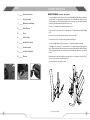
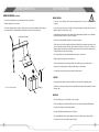
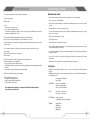
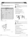
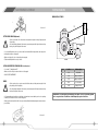
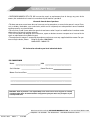
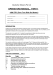
www.deutschermowers.com.au
DEUTSCHER H660-II
OWNER’S INSTRUCTION MANUAL
AND PARTS LIST
INDEX
ASSEMBLY INSTRUCTIONS
3
Assembly Instructions
5
Safety Instructions
7
Maintenance and Storage
13
Wiring Diagram
14
Chassis
15
Cutter Asembly
16
Handle Bars & Controls
17
Gearbox Assembly
19
Fuel Tank / Sundry Parts
20
Warranty
HANDLE ATTACHMENT
(Pre delivery) (Refer to Figure 1)
1. Connect the handles to the side rails of the chassis using four 75mm M8 bolts, while making sure that the ball
on gearbox linkage “ A” connects with the slotted tubular lever “B.” The ball and the tube should be greased to
make gear changes easier. The 75mm bolt through the rear hole on the right of the mower (facing forward) will
need to be inserted from underneath. Fasten the four nuts securely.
2. Insert a _” circlip into the groove in the end of the tubular lever “B”.
3. Fully loosen nut “C” and connect rod “D” to the drive clutch lever “E” using the washer and split pin. Retighten
nut “C”.
4. Connect the clutch return spring to the top of the drive clutch lever and to pin “F”.
5. Connect the rod “G” to the foot pedal assembly using a washer and split pin.
6. Connect the height adjusting rod H to the curved lever “J” using the bolt nut and washer provided.
7. See Figure 2. Place tank straps “L” in the tank bracket “K” slots and bend tabs up and back against the
bracket. Bolt the tank bracket to the handle bar assembly using three round headed bolts, with the round heads
of two bolts against the fuel tank. Place the fuel tank in position and attach the straps at their lower end using
two bolts.
8. Attach the throttle control to the handle bars ensuring the cable is free of sharp bends. Ensure both “choke”
and “stop” positions are achieved using the throttle lever.
9. Connect the fuel line from the tank to the engine.
H
J
D
F
C
B
G
A
E
2
Fig. 1 - Dealer Assembly
3
ASSEMBLY INSTRUCTIONS
SAFETY INSTRUCTIONS
ENGINE PREPARATION (Pre delivery)
BEFORE STARTING:
1. Remove the dipstick and add oil as per the instructions in the engine manual.
!
2. Add unleaded petrol to the petrol tank.
• Know your controls. Read the owners manuals thoroughly. Learn how to stop the engine quickly in an
emergency.
3. Follow the starting procedure listed below, and check there are no abnormal vibrations, and that the gear
lever, forward drive lever, height adjustment lever and blade clutch are functioning satisfactorily.
• Inspect the area to be mown, remove all debris and obstacles that may be in the path of the mower. Do not
attempt to shift obstacles while mower is going.
• Damaged blades and worn bolts are major hazards. Before starting, always visually inspect to see that blades,
blade bolts and cutter assemblies are not worn or damaged.
Attach throttle lever here.
• Replace worn or damaged blades and bolts in sets top preserve balance.
• Refuel outdoors only. Do not smoke while refuelling engine. Add fuel before starting the engine. Never remove
cap off the fuel tank or add petrol while the engine is running or the engine is hot. If petrol is spilled, do not
attempt to start the engine but move the machine away from the area of the spill and avoid creating any source
of ignition until the petrol vapours have dissipated.
• Do not allow children or people unfamiliar with these instructions to use the mower.
• With prolonged use, hearing protection should be worn.
K
• Never mow while barefoot or wearing open sandals, or thongs. Wear long trousers and heavy shoes.
L
• Apply sunscreen; wear appropriate clothing, a hat and sunglasses to avoid sunburn.
• It is advisable to wear suitable eye protection when operating the mower.
L
tab
STARTING:
• Disengage all blades and drive clutches and shift gear lever into neutral before starting the engine.
Fig. 2 - Fuel Tank Attachment
M
• Start the mower carefully according to instructions and with feet well away from blades and not in front of the
discharge chute.
OPERATION:
• Never mow while people, especially children, or pets are nearby.
• Mow only in daylight or in good artificial light. Stay alert for holes in the terrain and other hidden hazards.
• Never direct discharge of material towards bystanders.
• Avoid operating the equipment in wet grass, where feasible.
• Do not put hands and feet near or under rotating parts. Keep clear of the discharge opening at all times.
• Never pick up or carry a mower while the engine is running.
4
5
SAFETY INSTRUCTIONS
• Use extreme caution when reversing or pulling mower towards you.
• Do not carry passengers.
• Walk, never run.
• Slopes:
Do not mow excessively steep slopes.
Exercise extreme caution when on slopes.
For pedestrian controlled mowers, mow across the face of slopes, never up and down and exercise extreme
caution when changing direction on slopes.
MAINTENANCE & STORAGE
MAINTENANCE AND STORAGE:
• Keep all nuts, bolts and screws tight to be sure the equipment is in safe working condition.
• Do not use pressure-cleaning equipment.
• Never store the equipment with petrol in the tank inside a building where fumes can reach an open flame
or spark.
• Allow the engine to cool before storing in any enclosure.
• To reduce the fire hazard, keep the engine, silencer, battery compartment and petrol storage are free of grass,
leaves, or excessive grease.
• Use low throttle settings when engaging the ground drive, especially in high gears.
Reduce speed on slopes and in sharp turns to prevent overturning or loss of control.
• Replace worn or damaged parts for safety;
• Stop the blades when crossing surfaces other than grass and when transporting the mower to and from the
area to be mowed.
• If the fuel tank has to be drained, do this out-doors.
• Do not operate the engine in a confined space where dangerous carbon monoxide fumes can collect.
• Stop the engine:
Whenever you leave the mower, even for an instant.
Before re-fuelling.
• Stop the engine and disconnect the spark-plug lead, or turn off and remove key:
Before clearing blockages or unclogging chute:
Before checking, cleaning or working on the mower:
After striking a foreign object, inspect the mower for damage and make repairs before restarting and operating
the mower:
If mower starts to vibrate abnormally stop the engine immediately.
• Watch out for traffic when crossing or near roadways.
• Before leaving the operator’s position:
Disengage the cutter engagement lever,
Change into neutral and set the parking brake,
Stop the engine and or remove key.
• Replace faulty silencers.
• Do not change the engine governor settings or over speed the engine. Operating an engine at excessive speed
can increase the hazard to personal injury.
• Be careful during adjustment of the mower to prevent entrapment of the fingers between moving blades and
fixed parts of the mower.
• Store fuel in a cool place in a container specifically designed for the purpose. In general, plastic containers
are unsuitable.
• When the mower is to be parked, stored or left unattended, lower the cutting deck.
SPECIFICATIONS:
ENGINE: Honda and Briggs and Stratton engines are used, see engine owner’s manual supplied with
the mower.
GEARBOX: Deutscher Gear box houses two forward gears and reverse, incorporating a differential gearbox in
an oil bath alloy housing.
Recommended oil: EPX 85w/140
Capacity: 750ml
SPEED RANGE:
Low gear: 2.2 kph @ 2500rpm.
High gear: 3.6 kph @ 2500rpm.
Reverse gear: 1.7 kph @ 2500rpm.
TYRES:
Rear: 13-500-6 Pressure, 20psi
Front 250 x 4 Pressure, 20psi
CUTTING HEAD:
660mm cut, 2 x blades,
6 cutting height positions from 30mm-88mm.
GENERAL:
Length:1600mm
Width: 640mm
Height: 960mm
Weight: 120kg
Do not modify mower in any way, or use the mower with out the shields and guards in
place, they are for your protection.
6
7
MAINTENANCE & STORAGE
MAINTENANCE & STORAGE
CONTROLS:
TO DRIVE MOWER:
LIFT
• Release park brake.
• Select gear
Low forward: Raise and turn left
High forward: Raise and turn right
Reverse: Push down and turn right
LOW
HIGH
N
• Clasp clutch lever and hold to hand grip, releasing, To stop.
Illustration 1
WARNING! Use low throttle settings when engaging the traction-clutch,
especially in high gears
DEPRESS
GEAR
SELECTOR
TO ENGAGE CUTTER DRIVE:
PRE-START CHECK
Your Deutscher Mower comes to you tested and ready to operate, with engine and gearbox filled with oil.
• Read all safety instructions and know how to stop engine quickly in any emergency.
• Know your controls – Where they are and their function.
• Use fresh unleaded petrol. Do not mix oil with petrol.
• Ensure drive and cutter mechanisms are placed in neutral or disengaged.
• Set throttle setting to a position as not to stall engine on engagement.
• Place right foot on lever and press down and lock into position.
• To release, lift lever up with right foot.
OPERATION:
TO START THE ENGINE (Manual start):
• When engine is cold, move throttle lever to CHOKE position.
Illustration 2
• When engine is hot, move throttle lever to high throttle position.
• Slowly pull starter cord until starter pawls engage and rope stops then pull with force
turning the engine over. Repeat this procedure if the engine does not start.
Once engine is running shift throttle lever from Choke position to desired operating position.
TO STOP THE ENGINE: (Manual start)
• Push throttle lever to STOP position.
TO START THE ENGINE (Electric start version):
• When engine is cold, move throttle lever to CHOKE position.
• When engine is hot, move throttle lever to high throttle position.
• Turn key to start position and release once engine is running.
• Once engine is running shift throttle lever from Choke position to desired operating position.
MOWING ACROSS SLOPES AND REVERSING:
• As mentioned in the Safety Instructions, reduce speed on slopes and in sharp turns to prevent overturning and
loss of control. Mow across the face of slopes, never up and down.
• Wear suitable boots for the terrain. Do not continue mowing if you are slipping while walking. Exercise extreme
caution if the grass is damp.
• Do not mow an area with a slope greater than 10 degrees to the horizontal.
• Be extremely cautious when reversing. This is particularly important on slopes. Wear non slip footwear and
keep well back from the mower to ensure your footing is steady. Instantly release the drive lever if you feel
yourself slipping.
• When parking a mower on a slope, ensure the engine is turned off AND THE PARKING BRAKE IS ENGAGED,
before leaving the mower. This applies even if you leave the mower for an instant.
TO STOP THE ENGINE: (Electric start version)
TRANSPORTING AND LIFTING THE MOWER:
• Turn key to OFF position.
It is far safer to use ramps or a lifting device to put the mower onto a trailer or utility tray, rather than attempting
to lift it. Never attempt to lift the mower on your own.
8
9
MAINTENANCE & STORAGE
MAINTENANCE & STORAGE
MAINTENANCE
GEARBOX BELT (Replacement):
THE MANUFACTURES RESERVE THE RIGHT TO ALTER, CHANGE OR VARY THE SPECIFICATIONS OF THE
MACHINE OR ANY OF THE COMPONENT PARTS AT ANY TIME WITHOUT NOTICE.
LUBRICATION CHART
Lubrication
Engine
Daily
20hrs
100hrs
Refer to Engine Manual
Raise & Lower frame slides
• Remove belt guide. Part No 1619
• Remove nut “A” from adjustment pivot and remove from crank arm.
• To fit new belt, place belt over clutch adjustment rod and rap around pulleys.
Check
Kingpins
• Be careful during adjustment of the mower to prevent entrapment of the fingers between moving
blades and pulley’s fixed parts of the mower.
• Remove belt from pulleys and slide over clutch adjustment rod.
Gearbox
Change
!
• Before any inspection or replacements of the belts and associated parts turn engine off and pull
spark plug lead off spark plug.
x
Gear Oil
EPX 85w/140
Oil
x
Grease
x
Gear Control linkages
Oil
x
Clutch Control linkages
Oil
x
Height Control linkages
Oil
x
Throttle Cable
Oil
• Replace adjustment pivot to crank arm and tighten nut “A”.
x
• Refit belt guide. (ensure guide is bolted on the inside of the engine mounting plate)
• Adjust clutch: See CLUTCH ADJUSTMENT.
x
Illustration 6
GEARBOX
Use gear oil 85w/140
Capacity = 750ml
CUTTER BELT (Replacement):
!
• Before replacements of the belts and associated parts turn engine off and pull spark plug lead
off spark plug.
• Be careful during adjustment of the mower to prevent entrapment of the fingers between moving
blades, pulleys and fixed parts of the mower.
• Remove belt guide P No 1619 by unbolting from engine mounting plate.
• Remove gearbox belt from engine pulley.
• Ensure cutter belt is disengaged.
• Move cutter height lever to mid height position.
• Loosen “C” nut and brake lever stop to ensure belt is loose.
• Remove old belt and replace new belt feeding it around the pulleys and keeping the belt on the inside of the
guide pins.
• Place cutter in engaged position and adjust belt by adjusting nuts “C” & “B”.
Illustration 3
• Belt should have 20mm slack. DO NOT OVER TIGHTEN!
• Adjust brake lever stop to ensure cutter spindle stops when disengaged.
• Replace gearbox belt and refit belt guide. (Note: Belt guide bolted inside engine mounting plate.)
• Run and test to ensure all adjustments are correct.
10
11
MAINTENANCE & STORAGE
WIRING DIAGRAM
HONDA GXV390 UT1 DAEU
-
2
Illustration 7
5
+
7
CUTTER SPINDLE BRAKE (Adjustment):
!
3
• Before replacements of the belts and associated parts turn engine off and pull spark plug lead
off spark plug.
4
• Be careful during adjustment of the mower to prevent entrapment of the fingers between moving
blades, pulleys and fixed parts of the mower.
B LU E
R ED
8
• Loosen nut holding brake lever stop to chassis and slide forward until brake pad prevents cutter pulley from
rotating when cutters are disengaged.
GREEN
• Make sure brake pad is clear of cutter pulley when engaged.
• Tighten nut holding brake lever stop to chassis.
R ED
IB I G
IS
IM I L
1
B LACK
CLUTCH ADJUSTMENT FOR TRANSMISSION: (See Illustration 6)
• Loosen nut “C” and tighten nut “B”.
• Make sure belt is entirely free when clutch lever is disengaged.
• DO NOT OVER-TIGHTEN BELT.
BLADES:
!
• Before any inspection or replacements of the blades and associated parts turn engine off and
pull spark plug lead off spark plug.
Item
Part No.
Part Description
1
1261
Key Switch
2
1368
Battery lead 330mm
3
1373
Battery lead 250mm
4
R322
Loom assembly
5
H315
Battery 12 Volts
• Be careful during adjustment of the mower to prevent entrapment of the fingers between moving
blades and fixed parts of the mower.
• It is important that you visually inspect the blades, bolts and nuts to ensure that they are in a safe operating
condition; this should be done before each mowing period.
WARNING: Incorrect wiring may result in damage to the engines electrical system. Only qualified
and or competent electrical technicians should attempt any repairs or alterations.
• Always replace blades and bolts in kit form as to prevent any vibrations that may damage the mower and cause
personal injury.
Illustration 5
12
13
CUTTER ASSEMBLY
CHASSIS
4
12
5
7
8
13
14
2
10
1
3
6
8
8
18
9
28
5
4
2
7
20
9
26
19
3
1
10
22
11
5 6 7
15, 16 , 17
43
39
36
25
38
24
12
23
28
14
42
29
13
15
37
16
27
30
22
19
31
23
21
33
44
34
40
41
32
17
21
18
15
35
20
Item No.
1
2
3
4
5
6
7
8
9
10
11
12
13
14
15
16
17
18
19
20
21
22
14
Part No
1768
1463
1464
1465
1017
1018
1019
3015
1477
1472
1478
1479
1480
1481
Y556
1483
H616
1484
1487
1488
Part Description
Chassis Assembly
Connecting rod, front
Raise & lower rod, rear
Top cover.
Bolt 8mm x 20
Spring washer 8mm
Flat washer 8mm
Flanged Bush
King pin & stub axle RH
King pin & stub axle LH
Not used
Lock pin
Roll pin
Spring
Tyre 250-4
Rim & bearings
Tube 250-4
Wheel complete
Bearing 6203
Spring
Not used
Belt guide, idler pulley
Item No
23
24
25
26
27
28
29
30
31
32
33
34
35
36
37
38
39
40
41
42
43
44
45
Part No
1489
1492
1493
1496
1497
1498
HD123
1501
1502
1505
1460
1506
1507
1510
H59
1781
1513
1514
1517
1579
1429
1619
5002
25
Part Description
Pulley, engine
Key
Plate, clutch pulley
Wheel complete
Tube 13-500-6
Tyre 13-500-6
Rim assembly
Pin, axle drive
Pedal, blade engage
Rod, cutter engage.
Brake rod
Spring
Brake pedal, parking
Bearing 6202DRS
Bolt(1495)& nut (1511)
Stepped bush
Pulley
Pin, pivot
Arm, crank
Gear box belt.
Belt guard, B&S
Belt guide, engine.
Bronze bush, flanged.
24
26
27
Item
Part No
1
2
3
4
5
6
7
8
9
10
11
12
13
14
15
1646
2092
2093
3085
3095
1549
1530
3099
3104
1533
1536
2095
1541
1897
1898
H660
Part Description
Pulley
Brake disc x 4
Brake pad assembly
Brake lever
Brake lever stop
Spring, brake lever
Main guard
Deck attachment assy LH
Deck attachment assy RH
Side chute
Flap,
Nylon bush X 2
Hinge bar
Circlip
Bearing, spindle 6205
Cutting deck complete
Item
16
17
18
19
20
21
22
23
24
25
26
27
28
Part No
3107
1558
1585
1563
3098
1576
1306
1305
1303
1307
1060
1304
H650
H652
1578
H661
Part Description
Housing, spindle
Push rod
Connector, push rod
Spring, deck retract
Spindle & flange
Blade plate
Blade nut
Blade washer, belville
Blade x 2
Blade bolt
Spring washer 3/8” flat
Bolt, blade plate x 3
Blade, nut, bolt washer X 2
Nut,bolt & washer.x 2
V-belt, cutter,B66
Main Guard Inc chute & flap
15
GEARBOX ASSEMBLY
HANDLE BARS & CONTROLS
Item
New No.
1
2
3
4
5
6
7
8
9
10
11
1580
1583
1584
1586
1587
1590
1592
1506
1612
1618
1617
16
Part Description
Cable, throttle
Gear lever
Lever, throttle
Hand grip
Clutch lever
Vert. Clutch rod
Handle bars
Spring
Height lever
Knob 3/8W ID
Spring
Item
12
13
14
15
16
17
18
19
20
21
New No.
1618
1619
1624
1625
1629
1630
1631
1502
1495
Part Description
Knob 3/8” ID
Guide, gearbox belt
(Not used)
Spring
Selector arm and ball
Circlip, int 19mm
Bolt, nut and washer
Gear selector plate
Activator, blades
Pivot bolt and nut
17
FUEL TANK / SUNDRY PARTS
GEARBOX ASSEMBLY
3
2
3
Item No.
Part No.
1
1100
2
1640
3
18
Part Description
Qty
Item No.
Part No.
Part Description
Qty
Screw, pulley
1
35
1690
O-ring
2
Key
1
36
1691
Selector tappet Forward
1
1641
Spring washer
1
37
1695
Selector tappet reverse
1
4
1642
Washer
1
38
1739
High crown gear
1
5
1643
Pulley
1
39
1699
Bearing, needle, axle
4
6
1650
Spacer
1
40
1700
Spacer, diff.
4
7
1651
Seal 25x40x7
1
41
1701
Low crown gear
1
8
1652
Circlip 40mm
1
42
1702
Axle
2
9
1484
Bearing 6203
1
43
1704
Bolt, diff
4
10
1653
Input spindle
1
44
1705
Spring holder
2
11
1654
Plug ¾” UNF
1
45
1706
Spring
2
12
1655
Fibre washer ¾”
1
46
1707
Ball
2
13
1656
Bearing roller B128
1
47
1708
Housing R.H.
1
14
1657
Nut, axle 5/8” UNF
2
48
1714
Sleeve, bearing
1
15
1658
Spring washer
2
49
1715
Reverse gear 13 teeth
1
16
1315
2
50
1716
Bronze worm gear
1
17
1659
2
51
1717
Washer, hardened
1
18
1501
Flat washer
Seal, axle 7/8”x1,3/
8”x1/4”
Drive pin, axle
2
52
1740
High gear pinion & clutch
1
19
1661
Plug, ½” BSF
3
53
1719
Double clutch
1
20
1662
Fibre washer ½”
3
54
1720
Pinion, low gear
1
21
1663
Screw
2
55
1721
Circlip, 14mm
1
22
1637
Washer
2
56
1722
Sliding clutch with pins L.H.
1
23
1664
Bearing 6202
2
57
1723
Forward spindle
1
24
1665
Circlip 35mm
2
58
1724
Axle & clutch L.H. LSD
1
25
1666
Reverse spindle & gear
1
59
1725
Spacer
8
26
1669
Reverse clutch
1
60
1726
Clutch spreader bar
2
27
1670
Reverse sliding gear
1
61
1727
Spring
1
28
1671
Bearing, roller B98
2
62
1728
Sliding clutch R.H.
1
29
1672
Gasket
1
63
1729
Axle & clutch R.H. LSD
4
30
1673
Housing L.H.
1
64
1730
Diff spider gear
4
31
1680
Gear selector arm
1
65
1639
Bolt,5/16”x1-1/4”w
1
32
1688
Bolt, selector
2
--
HD151
Bar tread tyre LSD
2
33
1711
Selector guide
2
--
HD120
Gearbox complete
1
34
1689
Bolt, housing, ¼”x2”UNF
6
--
1
4
Item No.
1
2
3
4
Part No.
1746
1329
1747
1748
Part Description
Item No.
Part No.
Tank, 6.5lt
Cap, fuel tank
Strap
Bracket, tank
-
D2720
H641
Part Description
Paint, Deutscher Green 1lt tin
Decal set
19
WARRANTY POLICY
• DEUTSCHER MOWERS PTY. LTD. Will warrant the repair or replacement, free of charge, any parts of the
mower, that are defective in materials or workmanship or both for a period of:
24 months from the date of purchase.
• This does not cover normal ware abuse or incorrect service procedures as set out in the owner’s manual. Parts
such as blades, blade bolts, tyres and v-belts, which can be subjected, to use beyond their normal intended
working capacity are also excluded.
• This warranty is void if parts other than genuine have been used or if repairs or modifications have been made
without the manufactures written authority.
• This warranty does not obligate the manufacture, agents or dealers to cover transport costs incurred in the
repair or replacement of any defective part.
• The engine on this mower is covered by the engine manufactures warranty supplied with the mower. For your
nearest engine dealer, Phone:
Briggs & Stratton: 1800 650 042
Honda M.P.E.: 1800 241173
All claims to be referred to your local authorised dealer
FOR YOUR RECORD
Model:
H660
Serial Number:
Date of Purchase:
Mower Purchased From:
Remember: Proof of purchase is the responsibility of the owner and is necessary prior to warranty
work being under taken. An authorised dealer using genuine spare parts must carry out repairs or your
warranty will be void.
Manufactured in Australia by: DEUTSCHER MOWERS PTY LTD, 711 Creswick Road, Ballarat 3350
Telephone : 03 5339 5708
Part No. 17558
Edition: 1
June 2007
Fax: 03 5339 3189
www.deutschermowers.com.au