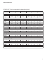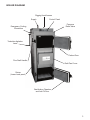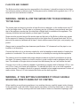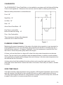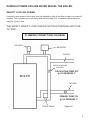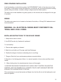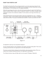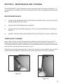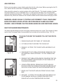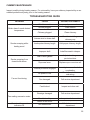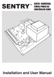
1
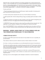
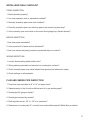
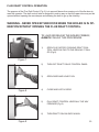
G A S I F I CAT I O N B O I L E R S
EBW AND
EBWC SERIES
HIGH EFFICIENCY
WOOD FIRED BOILERS
C
US
INS TAL L AT I O N A N D
OPE R AT I N G M A N UAL
G A S I F I CAT I O N B O I L E R S
Manufactured by:
Alternative Fuel Boilers
795 Deer Street
PO Box 281
Dunkirk, New York 14048
United States of America
Website: www.alternativefuelboilers.com
Email: [email protected]
© 2008 Alternative Fuel Boilers L.L.C.
all rights reserved.
Rev.20/10/08
INTRODUCTION
SPECIFICATIONS
BOILER DIAGRAM
TABLE OF CONTENTS
1
2
3
SECTION 1 - INSTALLATION INSTRUCTIONS
INTRODUCTION TO INSTALLERS
APPLICABLE STANDARDS
UNCRATING
LOCATING THE BOILER
COMBUSTION AIR SUPPLY
CONNECTING BOILER TO AN EXISTING SYSTEM
FLUE PIPE INSTALLATION
CLEARANCES
PLUMBING CONNECTIONS
PLUMBING CONNECTIONS DIAGRAM
FREESTANDING INSTALLATION
INSTALLER INSTRUCTIONS TO THE BOILER OWNER
WIRING DIAGRAMS
INSTALLERS FINAL CHECKLIST
4
4
4
4
5
7
9
10
10
11
12
12
13-16
17
SECTION 2 – OPERATING INSTRUCTIONS
WOOD-BURNING
STORAGE OF WOOD
CREOSOTE AND CLEANING
FLUE DRAFT CONTROL OPERATION
DRAFT FAN CONTROL UNIT
ELECTRICAL POWER FAILURE
BOILER OPERATING CHECKLIST
18
18
19
20
21
22
23
SECTION 3 - MAINTENANCE AND CLEANING
BOILER MAINTENANCE
TURBULATOR CLEANING
ASH DISPOSAL
HEAT EXCHANGER MAINTENANCE
CHIMNEY MAINTENANCE
TROUBESHOOTING GUIDE
24
24
25
25
26
26
SECTION 4 - ECONOBURN™ BOILER WARRANTY
WARRANTY PERIOD
CONDITIONS OF WARRANTY
WARRANTY
27
27
27
G A S I F I CAT I O N B O I L E R S
INTRODUCTION
Congratulations on the purchase of your new ECONOBURN™ Wood-Fired Boiler. Developed in
the northeastern United States, the ECONOBURN™ Boiler has been designed to allow you to
heat, and supply hot water for your home or business, by burning wood, one of North America’s
most plentiful and affordable fuels.
Your ECONOBURN™ Wood-Fired Boiler utilizes gasification burning technology to get an amazing 87% energy efficiency out of traditional wood fuel sources, and will provide you with many
years of safe, and cost effective space and water heating.
To ensure you have a clear understanding of the operating procedures of this boiler, please take
the time to read this manual thoroughly.
If you have any questions, you may contact us by email, through the ECONOBURN™ website at
www.alternativefuelboilers.com, or call toll free at 1-866-940-BURN (2876) and we will be happy
to answer them for you.
THIS UNIT MUST BE INSTALLED BY A QUALIFIED INSTALLER.
KEEP THIS MANUAL IN A SAFE PLACE FOR FUTURE REFERENCE. FOLLOW THE MANUAL CAREFULLY FOR CORRECT INSTALLATION AND OPERATION OF THE BOILER.
CAUTION – DO NOT FIRE THIS UNIT UNTIL OPERATING INSTRUCTIONS HAVE BEEN READ AND FULLY UNDERSTOOD.
INSTALL YOUR ECONOBURN WOOD-FIRED BOILER ONLY WITH AN
ALL FUEL CHIMNEY THAT IS IN GOOD CONDITION.
1
SPECIFICATIONS
ECONOBURN™ Specifications (subject to change without notice)
Boiler Model
EBW-100
EBW-150
EBW-200
EBW-300
EBWC-500
EBWC-1000
Depth
Width
Height
42”
25”
60”
42”
25”
64”
42”
30’
64”
45”
36”
70”
50”
40”
78“
80”
42”
82“
Firebox
Length
Width
Height
23”
15”
29”
23”
16”
29”
23”
21”
30”
26”
24”
34”
37”
29”
36”
50”
29”
39”
12” X 23.5”
13”X32”
13”X32”
Fire Box Door
(Dim.H x W)
12” X 15”
Water Volume
(US Gallons)
28
32
44
80
118
132
Water Pipe Size
Supply
Return
2”
2”
2”
2”
2”
2”
2.5”
2.5”
4”
4”
4”
4”
Flue Pipe Outside Diameter
8”
8”
8”
8”
12”
12”
Maximum Log Size
Length
21”
21”
21”
23”
33”
46”
12” X 15.75” 12” X 20.5”
Electrical Rating (All Models): Volts 120, 15 Amps
2
BOILER DIAGRAM
Rigging Hook Access
Supply
Control Panel
Pressure
Relief Valve
Emergency Cooling
Connection
Turbulator Agitation
Lever
Firebox Door
Flue Draft Handle
Draft Fan Cover
Return
(Lower back panel)
Gasification Chamber
and Ash Pit Door
3
SECTION 1 - INSTALLATION INSTRUCTIONS
INTRODUCTION TO INSTALLERS
(Save these Instructions!)
ATTENTION:THIS UNIT MUST BE
INSTALLED BY A QUALIFIED PROFESSIONAL!
Before installing this ECONOBURN™ Wood-Fired Boiler, please read the following instruction
manual carefully. This unit is designed to be a freestanding central heating boiler, or as an add-on
to operate in conjunction with an existing oil, gas, or electric unit, to provide a complete central
heating solution. Before installing be sure unit is properly sized for the intended application. Warranty does not cover misapplication of unit.
APPLICABLE STANDARDS
The ECONOBURN™ Wood-Fired Boiler must be installed in accordance with the requirements of
the National Fire Protection Association codes, the American Heating, Ventilation and Air Conditioning Code, The National Board of Fire Underwriters, and the U.L. Standards for solid fuel burning equipment. In all cases consult your local authorities and fire insurance company for specific
regulations.
UNCRATING
When you receive your ECONOBURN™ Wood-Fired Boiler, check it carefully to ensure that all
components are present and in good condition. If there has been any damage or loss in transportation, please notify the carrier at once. Remove the following from the boiler chambers: (2)
handles, aquastat, silicone, manual, boiler seal, (conditioning agent), pressure relief valve, and
circulator.
CHECKING COMBUSTION CHAMBER
The secondary combustion chamber, located in the lower part of the boiler, is a refractory that
should be centered from side to side, and front to back.
LOCATING THE BOILER
The location of the Boiler must be as close as possible to the tile-lined brick chimney, or factorybuilt solid-fuel approved chimney. Keep in mind also the day-to-day operation, and place for ease
of fueling and cleaning.
It is important to provide adequate combustion air to the Boiler. It may be necessary to add a
ventilator to an exterior wall of a closed Boiler room or an airtight basement. The Boiler must be
installed so that the clearances of those of local authorities are met.
If the Boiler must be installed on a combustible floor, a noncombustible base must be built. Two
layers of hollow masonry block (4” thick) are placed at right angles to each other so that the ventilation holes of one layer are opposite to those of the other layer.
Also for ember protection, there must be a minimum one layer of 26 ga. galvanized metal beneath
the masonry blocks. This base must extend beyond the Boiler to a minimum distance of 18” in
front and 8” on all sides.
4
With the location of the boiler selected the next step is to position the unit and proceed with assembly. If a noncombustible base is not required ECONOBURN™ recommends that the boiler be
placed on masonry blocks (bricks or 8” concrete blocks) if space permits, to allow easier fueling
and to keep the ECONOBURN™ boiler above any possible water in the basement. These blocks
should extend approximately 1” on all sides of the boiler for support and stability.
Continue as follows:
1. Plan all plumbing and electrical runs so that flue pipe is easily removable for cleaning and to
permit movement in the area as necessary.
2. Position masonry blocks and place the unit on top. Level the blocks as necessary.
3. Install aquastat wells, tridicator and pipe fittings using good quality pipe thread sealant or Teflon
tape.
4. Install the aquastats and complete the wiring, plumbing, smoke pipe and fire extinguishing tube
installations as shown in the appropriate electrical and plumbing diagrams.
5. IMPORTANT: Always test all functions under actual firing conditions before leaving the site. Test
especially for correct operation of damper, limit and by-pass zone valve and circulator.
Note: If the ECONOBURN™ boiler is installed above the radiation level, a low water cut off is required. It should be installed on pipe tees positioned at the supply and return points of the boiler.
WARNING - NEVER LEAVE START UP TO THE OWNER. EXPLAIN
THE OPERATIONS THOROUGHLY TO THE OPERATOR.
COMBUSTION AIR SUPPLY
Air inlets of at least 200 square inches free area must be provided to the room occupied by the
wood fired boiler.
These fresh air inlets must provide or allow free access of fresh outside air to the boiler.
At no time, or under any circumstances can a wood burning boiler be starved of combustion air.
The boiler must at all times be able to maintain the approved stack draft. The barometric draft regulator must be installed on the boiler smoke pipe in the same room or at least in such a way that
there is unrestricted free passage of air between the combustion air inlet to the boiler or burner
and the barometric draft regulator.
It is important to provide adequate combustion air to the boiler, a minimum 200 square inches
free area. It may be necessary to add a ventilator to an exterior wall of a closed boiler room or an
airtight basement.
Operating a wood or oil fired appliance with inadequate combustion air could be hazardous.
5
OUTSIDE COMBUSTION AIR MAY BE NECESSARY IF:
1. Fans that are installed in the fuel storage area create negative pressures in the room where
the solid fuel-burning appliance is located.
2. The solid-fuel-fired appliance does not draw steadily, smell, experiences smoke roll-out, burns
poorly, or back-drafts whether or not there is combustion present.
3. Any of the above symptoms are alleviated by opening a window slightly on a calm day.
4. The house is equipped with a well-sealed vapor barrier and tight fitting windows and/or has
any powered devices that exhaust house air.
5. There is excessive condensation on windows in the winter.
6. A ventilation system is installed in the house.
DO NOT CONNECT THIS UNIT TO A CHIMNEY FLUE SERVING ANOTHER APPLIANCE. BURN WOOD ONLY!
WARNING - RISK OF FIRE
1) DO NOT OPERATE WITH FUEL LOADING OR ASH REMOVAL
DOORS OPEN.
2) DO NOT STORE FUEL OR OTHER COMBUSTIBLE MATERIAL
WITHIN MARKED INSTALLATION CLEARANCES.
3) INSPECT AND CLEAN FLUES AND CHIMNEYS REGULARLY.
CAUTION - HOT SURFACES - KEEP CHILDREN AWAY!
DO NOT TOUCH DURING OPERATION!
6
BOILERS CONNECTED TO AN EXISTING SYSTEM
i. Shall be installed without interfering with the normal delivery of heated water from the original
boiler.
ii. Shall be installed without affecting the operation of the electrical and mechanical safety
controls of the original boiler.
iii. Shall provide for a changeover from one fuel to the other without requiring manual adjustment
of the controls or components either than the thermostats.
iv. Shall have provisions for preventing, or adequate water capacity within the boiler to prevent
damage from loss of circulation due to electrical power failure.
v. Shall be installed without changing the function of the controls or rewiring the original boiler.
A wiring interconnection is permitted. The electrical system of both boilers shall be powered
from a single branch circuit without exception.
2. A requirement in the recommended piping diagram for the installation of a hot-water circulation
loop that would dissipate at least 10% of the estimated rated heat output of the solid-fuel boiler
when circulation is reduced because of an electrical power failure.
i. The loop can only be made inoperative by a deliberate manual action.
ii. The design parameters for sizing shall be a pipe size > 3/4 inch (18 MM), room temperature of
65°F (18°C), and mean water temperature of 180°F (82°C).
iii. The loop be positioned above the boiler, with features that promote natural thermal circulation
of the water.
3. The recommended piping be such that excessive pressure will not be developed in any portion
of the boiler system.
KEEP THE DOORS CLOSED AND MAINTAIN SEALS IN GOOD CONDITION.
CLEANING OF THE HEAT EXCHANGER, FLUE PIPE, CHIMNEY AND
DRAFT INDUCER, IF USED, IS ESPECIALLY IMPORTANT AT THE END OF
THE HEATING SEASON TO MINIMIZE CORROSION DURING THE SUMMER MONTHS CAUSED BY ACCUMULATED ASH.
7
OPERATE THE (GAS, OIL, ELECTRIC) BOILER PERIODICALLY TO ENSURE THAT IT WILL OPERATE SATISFACTORILY WHEN NEEDED.
DO NOT RELOCATE OR BYPASS ANY OF THE SAFETY CONTROLS IN
THE ORIGINAL (GAS, OIL, ELECTRIC) BOILER INSTALLATION.
THE OPERATION OF THE GAS BOILER MUST BE VERIFIED FOR ACCEPTABLE OPERATION BEFORE AND AFTER INSTALLATION OF THE
ADD-ON APPLIANCE BY A GAS FITTER WHO IS RECOGNIZED BY THE
REGULATORY AUTHORITY.
DO NOT CONNECT TO ANY CHIMNEY OR VENT SERVING A GAS APPLIANCE.
The installation should comply with requirements of CAN/CSA-B365, and changes to the installation should comply with CSA B139 (for oil-fired), C22.1 (for electric), or CAN/CGA-B 149.1 or
CAN/CGA-B149.2 (for gas-fired).
8
FLUE PIPE AND CHIMNEY
The Boiler must be located as close as possible to the chimney. It should be ducted so that there
is a minimum number of elbows used. The flue pipe must be installed with a gradual rise of 1/2” or
more per foot from the Boiler to the flue.
WARNING - NEVER ALLOW THE SMOKE PIPE TO RUN DOWNHILL
TO THE FLUE.
The smoke pipe and chimney must be at least 8 inches in diameter, on the smaller sizes and 12”
on the two larger sizes. The flue pipe or a chimney may be of different cross-sectional area than
that of the appliance smoke pipe, provided that sufficient draft is available at the appliance. The
chimney should be low heat masonry or listed type HT pre-fab.
Space must be provided around the smoke pipe and the back of the Boiler to allow easy access
for the purpose of cleaning. Smoke pipes must not be lighter than 24 gauge black steel. All flue
pipe must be securely fastened with at least 3 sheet metal screws at every joint, and properly supported.
Always meet or exceed flue pipe clearance specifications -18” clearance from flue pipe to combustibles in all directions.
Connect the boiler only to a chimney suitable for solid fuel appliances and capable of venting the
products of combustion. Do not connect the boiler to a chimney flue serving another appliance.
The chimney must be installed with proper clearances above roof and from adjacent structures
and trees. If a masonry chimney is used it must be in good condition and be equipped with a tile
liner. Flue thimble or flue pipe must not extend into the chimney flue, as it will reduce the draft.
Connect only to a flue or chimney capable of maintaining a negative draft of between .02”w.c. min.
and .05”w.c. max. at all times and conditions. To maintain this draft, one or two draft regulators
may be required. To measure the draft, a gauge is needed to show negative pressure in inches of
water volume. Place a 1/4” hole between the boiler and the draft regulator.
WARNING - IF THIS SETTING IS EXCEEDED IT COULD CAUSE A
SOLID FUEL FIRE TO BURN OUT OF CONTROL.
When installing a wood-burning appliance to an existing chimney carefully inspect entire chimney
for the presence of old inlet holes, which may be improperly covered by metal caps or other unacceptable means. Fill any openings with brick and mortar to ensure no hazardous openings exist.
9
CLEARANCES
The ECONOBURN™ Wood-Fired Boiler is to be installed in accordance with the National Building
Code or local regulations. Allowances front and rear must be made for cleaning and servicing.
Minimum safety clearances to combustibles are:
Front: 48”
Right Side: 18”
Left Side: 24”
Rear: 24”
Above Wood-Fired Boiler: 28”
Flue Pipe to combustible,
Boiler and electrical wiring: 18”
Floor: Non-Combustible
These clearances will also allow adequate
combustion air to reach the boiler.
PLUMBING CONNECTIONS
Figure 1
Maintaining the proper temperature of the water in the boiler during operation is very important for
proper gasification to occur. The near boiler piping should be set up with a circulating loop (fig. 1)
using the factory setting of 150 degrees Fahrenheit. Once this temperature is reached, this circulator will turn off and the primary pump leads will energize.
At times, such as when there is a large call for heat, the return water temperature may become
too low. This can result in poor gasification and decreased efficiency, as well as creosote buildup
in the gasification chamber, heat exchanger tubes and chimney. Low return water temperature can
also shorten the life of the boiler.
A mixing valve should be installed at the boiler outlet in such a way that supply water can be
mixed with return water before it enters the bottom of the boiler. Check with your dealer or installer
for details.
OVER TEMP RELAY
If the boiler reaches a high temperature during operation, (220 degrees Fahrenheit), the over temp
relay will energize, the red light on the controller will come on, and an audible alarm will sound.
This relay also energizes the leads for a field installed, normally closed over temp valve, which will
be piped in the system to consume excess Btu’s not required.
10
DURING A POWER FAILURE NEVER REFUEL THE BOILER.
GRAVITY LOOP (NO POWER)
A normally open powered zone valve must be installed to allow a free flow of water in a power off
situation. The override loop for the safety shall have at least 30 ft. of radiation above the wood
boiler for a gravity flow.
THE SAFETY GRAVITY LOOP SHOULD NOT RUN THROUGH ANY PLASTIC PIPE.
PLUMBING CONNECTIONS DIAGRAM
AIR VENT
AQUASTAT
SUPPLY
CIRCULATOR PUMP
SUPPLIED
CIRCULATING PUMP OFF
@ 150 DEGREES °F
BOILER
RETURN
PRIMARY PUMP ON
@ 150 DEGREES °F
CHECK VALVE
Figure 2
11
FREE STANDING INSTALLATION
In the freestanding, or stand-alone system, the ECONOBURN™ boiler is the sole source of central heating. In this system connect the piping as you would for any conventional hydronic heating
system (using zone valves, circulator zoning, or single zone flow check system).
The boiler must not be installed as a gravity system, as the controls are not designed for this type
of operation.
WIRING
The boiler main power tie-in is located on the back of the boiler, a 15 Amp 120V dedicated circuit
is recommended.
WARNING - ALL ELECTRICAL WIRING MUST CONFORM TO NATIONAL AND LOCAL CODES.
INSTALLER INSTRUCTIONS TO THE BOILER OWNER
1. Keep area around unit clean.
2. Use SOLID wood only. Hardwood is preferred.
3. Load carefully.
4. Remove ash regularly as directed.
5. Watch for soot build up in Flue pipe, and Heat Exchanger.
6. Realize the danger of extreme overheating due to over firing.
7. Danger of flue fire if poor maintenance produces creosote buildup.
8. Operation of unit during power failure, (i.e. manual operation of zone valves and flow check
valves).
9. When shutting down for extended periods, clean unit thoroughly.
10. BEFORE RELOADING THE BOILER WITH WOOD, DRAFT CONTROL FAN MUST BE
STOPPED, AND FLUE DAMPER FULLY OPENED FOR AT LEAST ONE MINUTE BEFORE
OPENING THE LOADING DOOR TO REFUEL.
This is necessary to ensure that smoke and flames from the fire will not exit the loading door and
harm the operator.
12
BOILER WIRING DIAGRAM FOR
EWB-100 EWB-500 EWB-1000
Figure 3
13
BOILER WIRING DIAGRAM FOR
EWB-150 EWB-200 EWB-300
Figure 4
14
Figure 5
15
Figure 6
16
INSTALLERS FINAL CHECKLIST
PIPING INSPECTION
1. Boiler plumbed properly?
2. Is a new expansion tank or equivalent installed?
3. Normally closed by-pass zone valve installed?
4. Does the normally open zone valve by-pass to the main living area loop?
5. Is the normally open zone valve on the most direct piping loop (fewest elbows)?
BOILER INSPECTION
1. Are clearances maintained?
2. Is the system full of water and air eliminated?
3. Are zone valves and piping located to prevented drips on controls?
WIRING INSPECTION
1. Is main disconnecting switch within view?
2. Wiring cables protected from heat and not touching hot surfaces?
3. Check normally open zone valve (should heat gravity zone when valve open).
4. Check settings on all aquastats.
FLUE AND SMOKE PIPE INSPECTION
1. Flue inner size equivalent to 8” or 12” on larger sizes?
2. Separate entry to flue for both solid-fuel and oil or gas smoke pipes?
3. Smoke pipe 24 gauge or better?
4. Smoke pipe secured by screws?
5. Draft regulator set at -.02” to -.05” w.c. maximum?
6. Clearances of smoke pipe 18” or better from combustible material? Metal floor protection.
17
SECTION 2 – OPERATING INSTRUCTIONS
INITIAL STARTUP
To remove any remaining moisture in the refractory, a small to medium fire should be maintained for 10 to 12 hours.
WOOD-BURNING
The ECONOBURN™ Wood-Fired Boiler will burn most solid wood fuels, however it is recommended that hardwoods be used for their superior energy content. Burning dry seasoned wood is
alright, although unnecessary, as a residual moisture content of 20% is required for optimal gasification combustion.
Keep firing door tightly closed and check door seal condition regularly. The 10.3 oz. tube of hightemp, silicone provided with the boiler will aid in maintaining the seal of the pressurized chambers.
WARNING: DO NOT USE CHEMICALS OR FLUIDS TO START THE
FIRE OR DURING OPERATION. DO NOT BURN DRIFTWOOD, MANUFACTURED LOGS, WOOD CHIPS, SAWDUST OR PELLETS. DO NOT
BURN GARBAGE, GASOLINE, NAPHTHA OR ENGINE OIL.
WARNING: DRAFT CONTROL FAN MUST BE STOPPED, AND FLUE
DAMPER FULLY OPENED FOR AT LEAST ONE MINUTE BEFORE
OPENING THE LOADING DOOR TO REFUEL.
THIS IS NECESSARY TO ENSURE THAT SMOKE AND FLAMES
FROM THE FIRE WILL NOT EXIT THE LOADING DOOR AND HARM
THE OPERATOR.
STORAGE OF WOOD
DO NOT STORE WOOD WITHIN INSTALLATION CLEARANCES OR WITHIN
THE SPACE REQUIRED FOR CHARGING OR ASH REMOVAL.
LOAD FUEL CAREFULLY OR DAMAGE COULD RESULT. DO NOT USE AN
AUTOMATIC STOKER.
18
CREOSOTE AND CLEANING
1. Establish a routine for the storage of fuel, care of the appliance, and firing techniques.
2. Check daily for creosote build up until experience shows how often cleaning is necessary.
3. Be aware that the hotter the fire, the less creosote is deposited, and that weekly cleaning
may be necessary in mild weather, even though monthly cleaning may be enough in the coldest
months.
A small intense fire is preferable to a large smoldering fire to reduce the amount of creosote deposition.
4. Have a clearly understood plan to handle a runaway fire or chimney fire.
WARNING: IF A PROLONGED POWER FAILURE OCCURS DO NOT
FIRE THE UNIT UNTIL THE POWER SUPPLY RESUMES!
19
FLUE DRAFT CONTROL OPERATION
The purpose of the Flue Draft Control (Fig. 6) is to prevent flames from coming out of the fire door toward the operator. The draft control lever is designed in such a way so that the upper door may not be
opened without opening the rear damper and allowing the draft to go up the chimney.
WARNING - NEVER OPEN EITHER DOOR WHEN THE BOILER IS IN OPERATION WITHOUT OPENING THE FLUE DRAFT CONTROL.
TO LOAD OR RELOAD THE BOILER FIREBOX,
ALWAYS FOLLOW THIS PROCEDURE:
1)
OPEN FLUE GATE BY PUSHING DRAFT CONTROL LEVER AS FAR TO THE REAR AS IT WILL
GO (Fig.8).
2)
TURN OFF DRAFT FAN AT CONTROL PANEL.
3)
OPEN DOOR AND LOAD FUEL.
4)
CLOSE AND LATCH DOOR.
5)
PULL DRAFT CONTROL LEVER ALL THE WAY
FORWARD (Fig.9).
6)
TURN DRAFT FAN ON ONCE AGAIN.
Figure 7
Figure 8
Figure 9
20
DRAFT FAN CONTROL UNIT
The Draft Fan Controller (Fig.10) is an Aquastat which is set at the temperature desired for the
temperature of the water jacket of the boiler. A probe is clamped to the top of the boiler to monitor
this temperature. This is normally set at 160 degrees Fahrenheit.
When the temperature of the water is less then the Aquastat setting, the speed of the Draft Fan is
raised to maximum RPM, forcing air into the combustion chamber. This creates the highly efficient
gasification process in the combustion chamber. The fan remains on as long as the boiler is operational.
Packed with the boiler is a pump which would be used in the circulating loop. (Fig. 2 - Plumbing
Connections - Page 11) This increases internal water heating efficiency, as it actively circulates the
water within the boiler. This pump is activated when the boiler is turned on and shuts off at 150°F.
Figure 10
The Aquastat is made up of two temperature indicators.
The top numerical indicator is the temperature of the water in the boiler water jacket. This is monitored by a probe that lies in the upper portion of the boiler water jacket.
The lower numerical indicator displays the desired boiler water temperature setting. This is controlled by the increment-decrement buttons on the right side of the Aquastat.
The Overheat Indicator Lamp will light when the unit exceeds 220 degrees Fahrenheit.
21
The Thermo Overload switch protects the Control Panel from any electrical shorts or power surges
in excess of 5 amps with any external electrical devices wired through the rear of the boiler. This
could include the main or circulating pump, or an overheat valve if installed, and connected to the
electrical box at the rear of the boiler.
In the event of the breaker tripping, the switch will pop outwards. Simply press the switch back into
place to reset the breaker.
WARNING: DO NOT ADD MORE FUEL UNTIL YOU ARE CERTAIN
THAT ALL CONTROLS ARE FUNCTIONING PROPERLY AND NO
DAMAGE HAS BEEN DONE TO THE BOILER.
ELECTRICAL POWER FAILURE
NEVER REFUEL THE BOILER DURING A POWER FAILURE.
NEVER ATTEMPT TO OPERATE THE BOILER WITH NATURAL DRAFT BY
OPENING THE FLUE GATE.
It is advisable to install an auxiliary power supply to power the boiler during a power failure.
A gravity feed system should be on the boiler.
22
BOILER OPERATING CHECKLIST
a. Keep area around ECONOBURN™ boiler clean and clear of combustibles.
b. Use only wood. DO NOT burn any other combustible material, or liquid.
c. Remove ashes as directed.
d. Watch for soot in flue pipe - clean regularly.
e. Be aware of danger due to over firing unit.
f.
This unit is NOT suitable for automatic stoking.
g. Load carefully.
DRAFT CONTROL FAN MUST BE STOPPED, AND FLUE DAMPER FULLY
OPENED FOR AT LEAST ONE MINUTE BEFORE OPENING THE LOADING
DOOR TO REFUEL.
This is necessary to ensure that smoke and flames from the fire will not exit the loading door and
harm the operator.
h. Always observe the following minimum clearances to combustible materials:
Front 48”
Right side 18”
Left side and rear 24”
Flue pipe 18”
Floor must be non-combustible.
i. Maintain seals on firing door in good condition.
j. Establish a routine for storage of fuel, care of the appliance, and firing techniques.
23
SECTION 3 - MAINTENANCE AND CLEANING
The ECONOBURN™ Wood-Fired Boiler must be cleaned regularly to maintain top efficiency. A
good practice is to establish a routine for the storage of fuel, care of the appliance, and firing techniques.
BOILER MAINTENANCE
1)
TURBULATOR ARMS AND SHAFT SHOULD BE CLEANED EVERY 3 DAYS OF BOILER
USAGE WHEN THE UNIT IS HOT.
2)
ASHES SHOULD BE REMOVED AS NEEDED.
3)
CLEAN HEAT EXCHANGERS ANNUALLY WITH A 2 INCH BORE BRUSH OR SIMILAR
DEVICE.
4)
INSPECT REFRACTORY AND NOZZLES EVERY 6 MONTHS TO CHECK CONDITION.
TURBULATOR CLEANING
Every 3 days of boiler use, the Turbulator Arms and Shaft should be cleaned. To perform this
maintenance, grasp the Turbulator Agitation Lever on the upper left side of the boiler (Figs. 11 &
12), and firmly raise and lower it several times. The turbulator arm will only move a short distance
back and forth, and should be left as shown in Fig. 12.
When this lever is shaken back and forth, it clears the Turbulator Arms and Shaft of any buildup of
soot and ash that might have collected from the normal functioning of the boiler combustion.
Figure 11
Figure 12
24
ASH DISPOSAL
Before removing ashes, cease refueling and allow the fire to die down. Before opening the Ash Pit
door, ensure the fire in the boiler is completely extinguished.
Ashes should be placed in a metal container with a tight fitting lid. The closed container of ashes
should be placed on a non-combustible floor or on the ground, well away from all combustible
materials, pending final disposal. If the ashes are disposed of by burial in soil or otherwise locally
dispersed, they should be retained in the closed container until all cinders have thoroughly cooled.
WARNING: ASHES USUALLY CONTAIN LIVE DORMANT COALS, WHICH MAY
BURN FOR MANY HOURS AFTER A RECOGNIZABLE FLAME HAS DISAPPEARED. USE EXTREME CAUTION WHEN HANDLING AND DISPOSING ASHES.
HEAT EXCHANGER MAINTENANCE
The boiler Heat Exchanger must be thoroughly cleaned at least once a year. This consists of cleaning the Heat Exchanger tubes of accumulated soot and ash with a wire brush (Figs. 13 & 14)
TO CLEAN THE HEAT EXCHANGER FOLLOW THIS PROCEDURE:
1. REMOVE BACK AND TOP PANEL OF THE BOILER.
2. CUT INSULATION TO EXPOSE TOP CLEAN OUT.
3. REMOVE 1/4” STEEL TOP COVER PLATE.AND REAR FLUE
PLATE.
Figure 13
4. DISCONNECT THE TURBULATOR ROD BY REMOVING THE
NUT AND BOLT WHICH AFFIXES IT TO THE TURBULATOR
SHAFT.
5. REMOVE THE TURBULATOR ARMS BY GRASPING THE TURBULATOR CONNECTING ROD AND LIFTING THEM OUT OF
THE HEAT EXCHANGER.
6. USING A STEEL BRUSH, REMOVE ANY SOOT AND ASH
BUILDUP FROM THE TURBULATOR ARMS AND BRUSH OUT
ANY SOOT & ASH FROM THE HEAT EXCHANGER SHAFTS.
7. BRUSH OUT THE SOOT AND ASH FROM THE ASH CHAMBER.
Figure 14
8. REPLACE 1/4” STEEL TOP COVER PLATE AND REAR FLUE
PLATE MAKING SURE ALL CONNECTIONS ARE TIGHT,
SEALED WITH A HIGH TEMPERATURE SILICONE.
25
CHIMNEY MAINTENANCE
Inspect monthly during heating season. For extra safety, have your chimney inspected by an accredited professional yearly, prior to the heating season.
TROUBLESHOOTING GUIDE
PROBLEM
Boiler doesn’t reach desired
temperature.
Smoke escaping while
loading wood.
Smoke escaping from
closed boiler doors.
CAUSE
SUGGESTED REMEDY
Wood too moist.
Nozzle plugged.
Use properly seasoned wood.
Clean firebox.
Chimney plugged.
Clean chimney.
Intense wind or down draft.
Consider installing a
chimney cap.
Inadequate chimney length.
Add proper chimney length.
Improper draft.
Install barometric damper.
Leak in door gasket.
Adjust door hinges
per instructions.
Rope seal worn.
Replace rope or service call.
Thermal protection engages.
No power to unit.
Fan not functioning.
Fan making excessive noise.
Control settings and
indicators off.
Investigate reason for boiler
overheating.
Check fuse, breaker
and wiring.
Fan damaged.
Call service department.
Fan blocked.
Inspect and clean unit.
Bearings damaged.
Call service department.
Fan blades dirty.
Debris in fan cover.
Inspect and clean unit.
“
Call dealer or service
department.
Not determined.
26
SECTION 4 - ECONOBURN™ BOILER WARRANTY
WARRANTY PERIOD
The warranty period for the main boiler is 5 years against defects in workmanship. Any purchased
components will carry such warranty as covered by the particular vendor.
CONDITIONS OF WARRANTY
1. Your ECONOBURN™ boiler must be installed by a qualified, and licensed Plumbing and Heating professional. Any other method of installation will void this warranty.
2. User must have, and retain written proof of, an annual boiler inspection performed by a qualified boiler inspector.
WARRANTY
1. This warranty covers normal consumer use. It does not cover damages incurred in shipment or
that result from alteration, accident, misuse, abuse, neglect or commercial use.
2. We warrant each ECONOBURN™ boiler manufactured by Alternative Fuel Boilers to be free
from defects in material and workmanship under normal use and service; our obligation under
this warranty being limited to making good, at our factory, any part or parts which shall as defined
below, after installation by the original purchaser, be returned to us with transportation charges
prepaid and which our examination shall disclose to our satisfaction to have been defective, this
warranty being expressly in lieu of all other warranties express or implied, including the implied
warranties of fitness and merchantability, and of all other obligations or liabilities on our part, and
we neither assume nor authorize any other person to assume for us any other liability in connection with the sale of our boiler.
This warranty shall not apply to any ECONOBURN™ boiler which has been repaired or altered
outside of our factory or in any way so as, in our judgment, to affect stability or reliability, nor which
has been subject to misuse, negligence or accident, nor to any boiler made by us which shall not
have been operated in accordance with our printed instructions or beyond the factory rated capacity.
Alternative Fuel Boilers shall not in any event be liable for any consequences, damages, secondary charges, expenses of erecting or disconnecting, losses or damages resulting from alleged
defects to the apparatus. We make no warranty whatsoever with respect to pressure regulators,
piping, or other equipment or accessories which are warranted by their respective manufacturers.
3. This warranty shall not apply to any ECONOBURN™ boilers, or any parts of them, which have
been repaired or altered, without company’s written consent, outside company’s factory or altered
in any way so as, in the judgment of company, to affect adversely the stability or reliability of the
machine, or which have been subject to misuse, negligence, or accident, or have not been operated in accordance with company’s printed instructions or have been operated under conditions
more severe than, or otherwise exceeding, those set forth in the specifications for such machine.
27