1
MASTER THESIS
TITLE: Implementation of a Low Cost Video Wall using Raspberry Pi devices
MASTER DEGREE: Master of Science in Telecommunication Engineering &
Management
AUTHORS: Ramón García García
Carlos Viñas Rodríguez
DIRECTOR: Marc Fernández Vanaclocha
SUPERVISOR: Toni Oller Arcas
DATE: 24th April 2014
Thanks to Marc Fernández for guiding us during this project.
Thanks to i2CAT for providing us the necessary material.
Thanks to Toni Oller for supervising the project.
Overview
Keywords:
Video Wall, Raspberry Pi, H.264, Streaming
Description:
This project is a part of a more extensive project developed by i2CAT Foundation. The
aim of this master thesis is to build a Low Cost Video Wall using Raspberry Pi devices.
A Video Wall can be defined as an array of monitors or screens synchronized to
display content, simulating a bigger screen. This solution is the best alternative for
cost-effective indoor and outdoor commercial applications where display images and
video requires a larger screen size. A video wall solution can be composed of as many
monitors or screens as necessary to cover a desired area.
On the other hand, the Raspberry Pi is a credit-card-sized single-board computer
developed in the United Kingdom by the Raspberry Pi Foundation with the intention of
promoting the teaching of computer science.
The most innovative fact about the Raspberry Pi is its price: for less than 30 euros it is
possible to obtain a product that would have cost four or five times that amount before
the Raspberry Pi arrived on the market. This means that large sums of money can be
saved in some applications, especially in applications where a lot of separate devices
are needed.
A Video Wall requires one device per screen, and therefore the implementation of a
video wall using Raspberry Pi devices is a very interesting option. The main benefits
are that energy consumption and cost are both reduced enormously, making video
walls more accessible to enterprises which do not have massive funds, such as
museums, schools, shops, galleries and offices.
To achieve that end, several assigments has been performed. First, a study of the
operation of the video codecs supported by Raspberry Pi. Second, a testing of
different software available to stream and visualize videos using the device, and
finally, an analysis of the system to verify its correct behaviour.
Resum
Paraules clau:
Video Wall, Raspberry Pi, H.264, Streaming
Descripció:
Aquest projecte forma part d’un projecte més gran desenvolupat per la fundació
i2CAT. L’objectiu d’aquesta tesi és construir un Video Wall de baix cost emprant els
dispositius Raspberry Pi.
Podem definir un Video Wall com un conjunt de monitors o pantalles sincronitzades
per mostrar contingut de vídeos o imatges, simulant una pantalla de major dimensió.
Aquesta solució és una alternativa rendible per a les aplicacions comercials en
interiors i a l'aire lliure on es requereix mostrar imatges o vídeos en una pantalla més
gran. Una solució de Video Wall pot estar formada per tants monitors o pantalles com
sigui necessari per cobrir l'àrea desitjada.
D'altra banda, el dispositiu Raspberry Pi és un ordinador de placa única de la mida
d'una targeta de crèdit desenvolupada al Regne Unit per la Fundació Raspberry Pi,
amb la intenció de promoure l'ensenyament de la informàtica.
El factor innovador de Raspberry Pi és el seu preu: per menys de 30 euros pots
aconseguir un dispositiu amb unes característiques que haguessin costat quatre o
cinc vegades aquesta quantitat abans de que aquest arribés al mercat. Això implica
que es poden estalviar grans sumes de diners en algunes aplicacions, especialment
en aquelles on es necessita una gran quantitat de dispositius independents.
Un Video Wall requereix un dispositiu per pantalla, i per tant l'implementació d'un
Video wall utilitzant dispositius Raspberry Pi és una opció molt interessant. Els
principals beneficis són que el consum d'energia i el cost es redueixen enormement,
fent que els Video Walls siguin més accessibles per a les empreses que no compten
amb grans pressupostos, com per exemple, museus, escoles, botigues, galeries i
oficines.
Per tal d’aconseguir crear un Video Wall, s'han realitzat diverses tasques. En primer
lloc, un estudi del funcionament dels còdecs de vídeo compatibles amb Raspberry Pi .
En segon lloc, un test de diferents programes informàtics disponibles per fer
streaming i visualitzar vídeos utilitzant aquest dispositiu i, finalment, un anàlisi del
sistema per verificar el seu correcte funcionament.
INDEX
CHAPTER 1. INTRODUCTION........................................................................ 11
1.1. Work Structure ................................................................................................................... 11
1.2. What is a Video Wall? ........................................................................................................ 12
1.3. Project Objectives .............................................................................................................. 14
1.3. Server Features .................................................................................................................. 16
1.3.1. Server OS ................................................................................................................ 16
1.4. Client Features ................................................................................................................... 17
1.4.1. Client OS ................................................................................................................. 19
CHAPTER 2. PROTOCOL ARQUITECTURE ................................................. 20
2.1. Video Compression techniques ....................................................................................... 21
2.2. H.264 video codec .............................................................................................................. 23
2.2.1. Profiles and levels ................................................................................................... 23
2.2.2. Structure .................................................................................................................. 24
2.3. Real Time Protocol Operation ........................................................................................... 25
2.3.1 What is RTP.............................................................................................................. 25
2.3.2. RTP functions .......................................................................................................... 26
2.3.3. RTP packets and fields architecture ........................................................................ 26
2.4. Real Time Control Protocol operation ............................................................................. 29
2.4.1. What is RTCP .......................................................................................................... 29
2.4.2. RTCP functions ....................................................................................................... 29
2.4.3. RTCP fields and packets architecture ..................................................................... 30
2.5. MPEG-2 Transmission ....................................................................................................... 31
2.5.1. Building the MPEG Bit Stream ................................................................................ 31
2.5.2. MPEG Transport Stream ......................................................................................... 32
2.5.3. Format of a Transport Stream Packet ..................................................................... 33
CHAPTER 3. FRAMEWORKS......................................................................... 35
3.1. GStreamer ........................................................................................................................... 35
3.2. FFmpeg................................................................................................................................ 37
3.3. VLC ...................................................................................................................................... 39
3.4. OMXPlayer........................................................................................................................... 40
CHAPTER 4. MILESTONES ............................................................................ 42
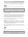
4.1. Deployment scenario 1 ...................................................................................................... 42
4.1.1. Milestone 1 - Playing back a H.264 Full HD Video.................................................. 43
4.2. Deployment scenario 2 ...................................................................................................... 45
4.2.1. Milestone 2 - Sending a HD/Full HD video to one Raspberry Pi ............................. 46
4.2.2. Milestone 3 - Sending a real time web cam video flow to one Raspberry Pi .......... 50
4.2.3. Milestone 4 - Receiving a Full HD video / WebCam and playing back ................... 51
4.2.4. Milestone 5 - Sending a Full HD video using MPEG-2 TS ...................................... 52
4.2.5. Milestone 6 - Receiving a Full HD video using MPEG2-TS .................................... 53
4.3. Deployment scenario 3 ...................................................................................................... 54
4.3.1. Milestone 7 - Extracting and sending the audio stream from a Full HD video ........ 55
4.3.2. Milestone 8 - Receiving and playing back the Full HD audio stream ...................... 55
4.4. Deployment scenario 4 ...................................................................................................... 56
4.4.1. Milestone 9 - Splitting and sending Full HD video to Raspberry Pi devices ........... 57
4.4.2. Milestone 10 - Receiving a Full HD/Cam and playing back / cropping the video .... 60
4.4.3. Milestone 11 - Combining Milestone 2 and Milestone 7 .......................................... 60
4.5. Translation of GStreamer Pipelines to C Code ............................................................... 61
CHAPTER 5. SYNCHRONIZATION ................................................................ 62
5.1. GStreamer ........................................................................................................................... 62
5.2. FFmpeg................................................................................................................................ 66
CHAPTER 6. CPU USAGE COMPARISON .................................................... 67
6.1. GStreamer ........................................................................................................................... 67
6.2. FFmpeg................................................................................................................................ 69
6.3. VLC ...................................................................................................................................... 71
6.4. OMXPlayer........................................................................................................................... 73
CHAPTER 7. NETWORK TESTING ................................................................ 74
7.1 DummyNet............................................................................................................................ 74
7.2. DummyNet Scenario .......................................................................................................... 75
7.3. DummyNet Configuration .................................................................................................. 75
7.4. Performed test and results ................................................................................................ 76
CHAPTER 8. THROUGHPUT AND BACKPLANE ANALYSIS....................... 78
8.1. Milestone 9 - Throughput and Backplane ........................................................................ 78
8.2. Milestone 11 - Throughput and Backplane ...................................................................... 79
CHAPTER 9. VIDEO WALL CONTROL SYSTEM .......................................... 81
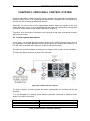
9.1. Control system description ............................................................................................... 81
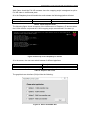
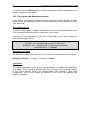
9.2. Startup scripts configuration ............................................................................................ 83
CHAPTER 10. COMPARISON WITH COMERCIAL PRODUCTS ................... 85
10.1. SAGE Overview ................................................................................................................ 85
10.2. SAGE Features and Tiled Display Wall Configurations ............................................... 86
10.3. SAGE Minimum Systems Requirements and Minimun Budget................................... 86
10.4. Minimum Systems Requirements and Budget of this project ..................................... 88
10.5. Comparison of the power consumption results ........................................................... 89
10.6. Throughput and Backplane analysis ............................................................................. 90
CHAPTER 11. PROJECT PLANNING ............................................................ 91
CHAPTER 12. CONCLUSIONS....................................................................... 93
CHAPTER 13. BIBLIOGRAPHY...................................................................... 96
ANNEXES ...................................................................................................... 102
ANNEX A. RASPBIAN OS INSTALLATION ................................................. 103
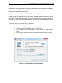
A1. Preparing our SD card for the Raspberry Pi ............................................................. 104
A2. Installation Raspbian “wheezy” ................................................................................. 105
A3. Configuration of Raspberry Pi Network ..................................................................... 106
ANNEX B. GSTREAMER INSTALLATION ................................................... 111
B1. Installing GStreamer 1.0 in the Server ...................................................................... 112
B2. Installing GStreamer 1.0 in the Clients ..................................................................... 114
ANNEX C. VLC INSTALLATION ................................................................... 115
C1. Installing VLC in the Server ...................................................................................... 116
C2. Installing VLC in the Clients ...................................................................................... 116
ANNEX D. H261 AND H263 VIDEO CODECS .............................................. 119
D1. H.261 video codec .................................................................................................... 120
D2. H.263 video codec .................................................................................................... 122
ANNEX E. GSTREAMER PIPELINES GRAPHS........................................... 123
E1. Milestone 1 ................................................................................................................ 125
E2. Milestone 2 ................................................................................................................ 125
E3. Milestone 3 ................................................................................................................ 125
E4. Milestone 4 ................................................................................................................ 125
E5. Milestone 5 ................................................................................................................ 126
E6. Milestone 6 ................................................................................................................ 126
E7. Milestone 9 ................................................................................................................ 126
Figure list
Figure 1. 3x3 Video Wall ............................................................................................. 12
Figure 2. System components .................................................................................... 14
Figure 3. HP Pavilion DV6 Notebook PC .................................................................... 16
Figure 4. Debian OS Logotype .................................................................................... 16
Figure 5. Raspberry Pi Model B components .............................................................. 17
Figure 6. Raspberry Pi Components Description ........................................................ 17
Figure 7. Raspbian OS ............................................................................................... 19
Figure 8. Set of protocols and video codecs available for the project .......................... 20
Figure 9. Protocol Layers involved in the Streaming ................................................... 20
Figure 10. Block diagram of video compression .......................................................... 22
Figure 11. Motion compensation ................................................................................. 22
Figure 12. RTP Header format .................................................................................... 26
Figure 13. Combining elementary streams from encoders into a TS or a PS .............. 32
Figure 14. Single Program Transport Stream (Audio and Video PES) ........................ 32
Figure 15. MPEG-2 Transport Stream Header Description ......................................... 33
Figure 16. GStreamer framework logo ........................................................................ 35
Figure 17. FFmpeg logo.............................................................................................. 37
Figure 18. VLC Logotype ............................................................................................ 39
Figure 19. Deployment scenario 1 .............................................................................. 42
Figure 20. Deployment scenario 2 .............................................................................. 45
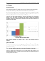
Figure 21. FFmpeg statistics Milestone 1 .................................................................... 47
Figure 22. FFmpeg statistics Full HD video ................................................................. 48
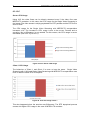
Figure 23. FFmpeg statistics (CRF applied) ................................................................ 49
Figure 24. Mark undefined packets – VLC .................................................................. 49
Figure 25. Deployment scenario 3 .............................................................................. 54
Figure 26. Deployment Scenario 4 .............................................................................. 56
Figure 27. Video cropping example............................................................................. 58
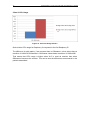
Figure 28. FFmpeg statistics ....................................................................................... 59
Figure 29: Video Wall syncronization example ............................................................ 62
Figure 30. GStreamer System clock and audio clock .................................................. 62
Figure 31. GStreamer SPS, PPS, SEI and IDR frames .............................................. 63
Figure 32. GStreamer non-IDR frames ....................................................................... 63
Figure 33. H.264 bitmap of IDR frame ........................................................................ 63
Figure 34. H.264 bitmap of non-IDR frames (P) .......................................................... 64
Figure 35. H.264 bitmap of non-IDR frames (B) .......................................................... 64
Figure 36. FU-A Marked packet .................................................................................. 65
Figure 37. H.264 video flows packets ......................................................................... 65
Figure 38. FFmpeg Wireshark Capture ....................................................................... 66
Figure 39. Server CPU Usage Comparison ................................................................ 67
Figure 40. Raspberry 1 CPU Server Usage Comparison ............................................ 68
Figure 41. Raspberry 2 CPU Server Usage Comparison ............................................ 68
Figure 42. CPU Usage FFmpeg Server ...................................................................... 69
Figure 43. CPU Usage FFmpeg Raspberry 1 ............................................................. 70
Figure 44. CPU Usage FFmpeg Raspberry 2 ............................................................. 70
Figure 45. VLC Server CPU Usage............................................................................. 71
Figure 46. VLC CPU usage Client 1............................................................................ 71
Figure 47. VLC CPU Usage Client 2 ........................................................................... 72
Figure 48. OMXPlayer CPU usage ............................................................................. 73
Figure 49. DummyNet Operation ................................................................................ 74
Figure 50. DummyNet Testing Scenario ..................................................................... 75
Figure 51. Throughput 960x540 single flow ................................................................ 78
Figure 52. Backplane capacity Milestone 9 ................................................................. 79
Figure 53. Throughtput 1920x1080 single flow............................................................ 79
Figure 54. Backplane capacity Milestone 11 ............................................................... 80
Figure 55. Commercial use scenario........................................................................... 81
Figure 56. Start up screen Raspberry Pi devices ........................................................ 82
Figure 57. Server VideoWall GUI ................................................................................ 82
Figure 58. SAGE working demonstration .................................................................... 85
Figure 59. Project time line ......................................................................................... 92
Annex Figure List
Figure A1. SD Formatter V4.0 Configuration ............................................................. 104
Figure A2. Win32 Disk Imager Configuration ............................................................ 105
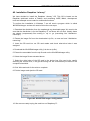
Figure A3. Advanced IP Scanner Program ............................................................... 106
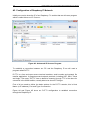
Figure A4. PuTTY Configuration (1) .......................................................................... 107
Figure A5. PuTTY Configuration (2) .......................................................................... 107
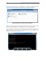
Figure A6. Connection established ........................................................................... 108
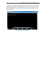
Figure A7. Session terminal of Raspberry Pi ............................................................. 108
Figure A8.Wireless Connection shared - Windows 7................................................. 109
Figure A9. Network interface configuration ............................................................... 109
Figure A10. DNS configuration file ............................................................................ 110
Figure B1. A block diagram of H.261 video codec..................................................... 120
Table list
Table 1. List of components and its functionality ......................................................... 15
Table 2. Raspberry Pi Minimum Recommended Specifications .................................. 18
Table 3. Frameworks and components relationship .................................................... 35
Table 4. Initial Scripts in Raspberry Startup ................................................................ 81
Table 5. Initial Script for Audio .................................................................................... 82
Table 6. Scripts in the server ...................................................................................... 82
Table 7. IP and Port configuration ............................................................................... 83
Table 8. Basic SAGE Cost .......................................................................................... 87
Table 9. Our system cost ............................................................................................ 88
Table 10. 2x2 Project Video Wall cost ......................................................................... 88
Table 11. Fundamental elements to compare with SAGE ........................................... 88
Table 12. Basic SAGE Power Consumption ............................................................... 89
Table 13. Basic Power Consumption of our system .................................................... 89
Table 14. Task table ................................................................................................... 92
Table 15. Frameworks results comparison.................................................................. 94
Table 16. H261 picture format ................................................................................... 120
Table 17. Macroblocks in GOB - H261 ...................................................................... 120
Table 18. Luminance and Chrominance per macroblock .......................................... 121
Table 19. H263 picture formats ................................................................................. 122
11
Implementation of a Low Cost Video Wall using Raspberry Pi devices
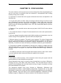
CHAPTER 1. INTRODUCTION
This chapter focuses on explaining in detail the work structure of this project, what a
video wall is, the objectives of the project and the main features of the components
employed in this thesis.
1.1. Work Structure
The work structure of this project has been organized in 12 chapters. For each one, a
brief description of the work done is provided.
In chapter 1, a description of the work structure used in this project is shown, a
description of a video wall is explained, the project objectives are presented and the
main system components needed are widely detailed.
In chapter 2, the video compression techniques have been studied, focusing on H264
video codec. This video codec provides enhanced compression efficiency and network
friendly video representation for interactive and non-interactive applications (broadcast,
streaming, storage and video on demand). It is designed to support a wide variety of
applications and to operate over several types of networks and systems.
In chapter 3, an investigation of several software/frameworks available to form our
video wall have been done. The frameworks are GStreamer, FFmpeg, VLC and
OMXPlayer. They allow us to write a variety of instructions that permit to crop, stream
and play back Full HD videos in our Raspberry Pi devices.
Chapter 4 is the core of the project and it is organized as a set of different milestones
or test cases. It contains the deployment scenarios, the development of each milestone
and the results obtained using different frameworks, previously explained in chapter 3.
Chapter 5 is focused on demostration of synchronization between the Raspberry Pi
devices that set up the video wall. Different measures have been done using a network
protocol analyser, called Wireshark, to evaluate the synchonization obtained using
GStreamer and FFmpeg framework.
Chapter 6 is devoted to measure CPU usage in all the components of the videowall for
every test case described in chapter 4. This provides information about which one of
the frameworks is the most effective in terms of CPU usage.
Chapter 7 is devoted to test the system network. To perform the testing, a program
called DummyNet has been used. It allows to know the behaviour of the video wall in a
non-ideal network, by measuring the response of the system against network losses
and delays.
In chapter 8, throughput and backplane analysis are performed. By using Wireshark,
some measures are performed in the deployment scenarios to know the traffic that
network components (router or switch) should support.
Chapter 9 describes how to implement a user friendly real case commercial scenario. It
is a control system that allows the user to select the type of data to stream and how
visualise it.
12
Implementation of a Low Cost Video Wall using Raspberry Pi devices
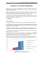
Chapter 10 provides a comparison of the system implemented with current commercial
products (SAGE) in terms of cost, power consumption and backplane to demostrate
that the system can compete in these three aspects.
Chapter 11 shows the timeline of the project and how tasks and time have been
organized.
Finally, chapter 12 contains the project conclusions, a comparison of the results
obtained for each framework and the environmental impact.
1.2. What is a Video Wall?
A video wall consists of multiple computer monitors, video projectors, or television sets
tiled together contiguously or overlapped in order to form one large screen. Typical
display technologies include LCD panels, LED arrays and rear projection screens.
Screens specifically designed for use in video walls usually have narrow bezels in
order to minimise mullion - the gap between active display areas - and are built with
long-term serviceability in mind. Such screens often contain the hardware necessary to
stack similar screens together, along with connections to daisy chain power, video, and
command signals between screens. A command signal may, for example, power all
screens in the video wall on or off, or calibrate the brightness of a single screen after
bulb replacement.
Reasons for using a video wall instead of a single large screen can include the ability to
customize tile layouts, greater screen area per unit cost, and greater pixel density per
unit cost, due to the economics of manufacturing single screens which are unusual in
shape, size, or resolution.
Figure 1. 3x3 Video Wall
13
Implementation of a Low Cost Video Wall using Raspberry Pi devices
Video walls are sometimes found in control rooms, stadiums, and other large public
venues. However,it is also possible to find simple video walls that can be driven from
just using a set of personal computers and a set of monitors screen at home.
Video Wall Latest Advancements
Researchers around the U.S. have been advancing video wall technology in recent
years and are listed below:
SAGE
Jason Leigh and others at the Electronic Visualization Laboratory, University of Illinois,
Chicago, developed SAGE, the Scalable Adaptive Graphics Environment, allowing the
seamless display of various networked applications over a large display wall (LDW)
system.
Different visualization applications such as 3D rendering, remote desktop, video
streams, and 2D maps, stream their rendered pixels to a virtual high-resolution frame
buffer on the LDW. Using a high-bandwidth network, remote visualization applications
can feed the streams of the data into SAGE.
The user interface of SAGE, which works as a separate display node, allows users to
relocate and resize the visualization stream in a form of window, which can be found in
a conventional graphical user interface. Depending on the location and size of the
visualization stream window on the LDW, SAGE reroutes the stream to respective
display nodes.
Chromium
Chromium is an OpenGL system for interactive rendering on graphics clusters. By
providing a modified OpenGL library, Chromium can run OpenGL-based applications
on a LDW with minimal or no changes. One clear advantage of Chromium is utilizing
each rendering cluster and achieving high resolution visualization over a LDW.
Chromium streams OpenGL commands from the application node to other display
nodes of a LDW. The modified OpenGL library in system handles transferring OpenGL
commands to necessary nodes based on their viewport and tile coordinates.
Media Fusion
David Hughes and others from SGI developed Media Fusion, an architecture designed
to exploit the potential of a scalable shared memory and manage multiple visual
streams of pixel data into 3D environments. It provides data management solution and
interaction in immersive visualization environments. Its focus is streaming pixels across
heterogeneous network over the Visual Area Network (VAN) similar to SAGE.
However, it is designed for a small number of large displays. Since it relies on a
relatively small resolution for the display, pixel data can be streamed under the
fundamental limit of the network bandwidth.
Hiperwall, Inc.
Based on video wall display technology developed at University of California, Irvine’s
California Institute for Telecommunications and Information Technology (Calit2),
Hiperwall, Inc. was formed to commercialize a video wall system that offers advanced
software functionality and interface with standard PCs, monitors and Ethernet network.
14
Implementation of a Low Cost Video Wall using Raspberry Pi devices
The system displays high-resolution still images, HD videos, live HD video streams and
PC applications. Multiple feeds can be displayed on the wall simultaneously and users
can reposition and resize each feed in much the same way they move and resize
windows on a PC desktop. Each feed can be scaled up for viewing on several monitors
or the entire wall instantly depending upon the user’s discretion.
1.3. Project Objectives
The requirements that should be complied in the implementation of our Low Cost video
Wall are the following:
1. Low Cost
2. Being able to play back a Full HD 1080p video stream.
3. Providing synchronization between Raspberry Pi’s.
4. Using H.264 as a video compression format.
5. Use of Real Time Protocol as Application layer.
6. Use of User Datagram Protocol as Transport Layer.
7. Minimum latency in reception.
8. Scalable.The aim is to increase easily the screen matrix (2x2, 3x3, 4x4, etc.).
9. Robust. The system can be recovered in case of network losses or network
delays.
To implement this, a notebook that will act as a server will be used to emit and encode
the video streams and two Raspberry Pi devices to decode and visualize each part of
the video. The criteria to use Raspberry Pi devices is that they provide H.264 hardware
decoding43 and that they are very cheap.
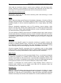
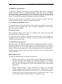
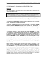
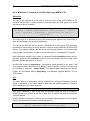
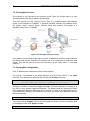
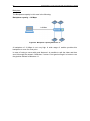
The following figure shows the components of our video wall system. Later on, in the
following sections, the components utilized in this project are explained in detail.
Figure 2. System components
15
Implementation of a Low Cost Video Wall using Raspberry Pi devices
Component
Description and Functions
Source
The source is a notebook that acts as a
server and its function is to stream
encoded audio and video flows to the
receivers using some scripts.
Switch / Router
This element is in charge of distributing
the flow sent by the server to the different
receivers.
Receivers
The receivers are the five Raspberry Pi
devices. Four of them are running a script
that decode, crop and play back the video
stream. The fifth Raspberry is responsible
for decoding the audio stream and play
back the audio through the speakers.
Speakers
The speakers are connected to the
Raspberry Pi through a 3.5 mm jack to
provide stereo audio.
Screens
Screens are connected to Raspberry Pi
devices using HDMI to HDMI lead or
HDMI to DVI lead.
Table 1. List of components and its functionality
16
Implementation of a Low Cost Video Wall using Raspberry Pi devices
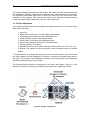
1.3. Server Features
The server in this project is a HP Pavilion DV6 Notebook PC.
Figure 3. HP Pavilion DV6 Notebook PC
The server has the following features:
-
CPU: Intel Core i3 M330 2.13 GHz (4 CPUs)
-
RAM: 4 GB
-
GPU Card: NVIDIA GeForce G105M
-
Operating System (OS): Debian GNU/Linux 7.1 (wheezy)
-
Hard Disk Drive Size: 78 GB Logic Partition
1.3.1. Server OS
The server uses Debian GNU/ Linux 7.1 as OS because Raspberry has installed a
version of Debian for Raspberry Pi devices. Furthermore all the programs used during
the project are compatible with Debian.
Debian provides more than a pure OS: it comes with over 37500 packages;
precompiled software bundled up in a nice format for easy installation on the laptop.
Figure 4. Debian OS Logotype
17
Implementation of a Low Cost Video Wall using Raspberry Pi devices
The Debian Project is an association of individuals who have made common cause to
create a free operating system.
1.4. Client Features
The Raspberry Pi is a credit-card sized computer that plugs into the TV and a
keyboard. It is a capable little PC which can be used for many of the things that a
desktop PC does, like spreadsheets, word-processing and games. The more important
thing for this project is that it can play high-definition video.
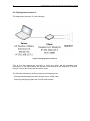
During the project 2 Raspberry Pi (Model B) have been used. Its components are
shown in Figure 5.
Figure 5. Raspberry Pi Model B components
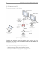
Figure 6 and Table 1 show the minimum recommended specifications for each
component.
Figure 6. Raspberry Pi Components Description
18
Implementation of a Low Cost Video Wall using Raspberry Pi devices
Item
Minimum recommended specifications
1 - SD card
Minimum size 4Gb; class 4 (the class indicates how fast the
card is). It is recommended using branded SD cards as they
are more reliable.
2a - HDMI to HDMI /
DVI lead
HDMI to HDMI lead (for HD TVs and monitors with HDMI
input) or HDMI to DVI lead (for monitors with DVI input).
2b - RCA video lead
A standard RCA composite video lead to connect to your
analogue display if you are not using the HDMI output.
3 - Keyboard and
mouse
Any standard USB keyboard and mouse should work.
Keyboards or mice that take a lot of power from the USB
ports, however, may need a powered USB hub. This may
include some wireless devices.
4 - Ethernet (network)
cable [optional]
Networking is optional, although it makes updating and
getting new software for the Raspberry Pi much easier.
A good quality, micro USB power supply that can provide at
least 700mA at 5V is essential. Many mobile phone chargers
are suitable - the label on the plug needs to be checked.
5 - Power adapter
If the supply provides less than 5V then the Raspberry Pi
may not work at all, or it may behave erratically. Be wary of
very cheap chargers: some are not what they claim to be. It
does not matter if the supply is rated at more than 700mA.
6 - Audio lead
[optional]
If HDMI is used, digital audio will be achieved via this. If the
analogue RCA connection is used, stereo audio will be
available from the 3.5mm jack next to the RCA connector.
Table 2. Raspberry Pi Minimum Recommended Specifications
Focusing the attention on the model of 2 Raspberry Pi devices, these devices have the
following features:
-
Size: 85.60 mm × 53.98 mm
-
CPU: ARMv6 –compatible processor rev 7 (v61) - (700 MHz)
-
GPU Card: BroadCom BCM27081,2,3,4
-
SDRAM: 512 MB
19
Implementation of a Low Cost Video Wall using Raspberry Pi devices
-
2 x USB 2.0 , 10/100 MBIT
-
HDMI output.
Some small differences that will affect the performance have been encountered
between both Raspberry Pi devices. This is a constraint because the RAM of both
Raspberry Pi devices are not the same:
Raspberry 1 (Son Goku)
- Samsung 240 K4P4G324EB-AGC1 GKI59790
Raspberry 2 (Krilin)
- Samsung 240 K4P4G324EB-AGC1 GKI597M
It is not possible to know whether there are differences in the BroadCom SoC because
they are physically placed under the Samsung RAM.
1.4.1. Client OS
Raspbian5,6 is a free operating system based on Debian optimized for the Raspberry Pi
hardware.
The initial build of over 35,000 Raspbian packages, optimized for best performance on
the Raspberry Pi, was completed in June of 2012. However, Raspbian is still under
active development with an emphasis on improving the stability and performance of as
many Debian packages as possible.
Figure 7. Raspbian OS
Raspbian is an unofficial port of Debian Wheezy armhf with compilation settings
adjusted to produce optimized "hard float" code that will run on the Raspberry Pi. This
provides significantly faster performance for applications that make heavy use of
floating point arithmetic operations.
All other applications will also gain some performance through the use of advanced
instructions of the ARMv6 CPU in Raspberry Pi.
Although Raspbian is primarily the efforts of Mike Thompson and Peter Green, it has
also benefited greatly from the enthusiastic support of Raspberry Pi community
members who wish to get the maximum performance from their device.
In Annex A, how to install and configure Raspbian OS in Raspberry Pi devices is
explained.
20
Implementation of a Low Cost Video Wall using Raspberry Pi devices
CHAPTER 2. PROTOCOL ARQUITECTURE
This chapter is centered on the different standards of real time video transmission. The
different protocols used in the project to implement the video wall are explained.
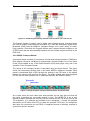
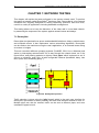
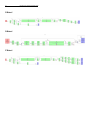
The following two figures describe the set of protocols and video codecs used in the
project. In the following sections the most relevant aspects of H.264, Real Time
Protocol (RTP) and Real Time Control Protocol (RTCP) are explained.
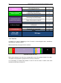
In Figure 8, the set of protocols and video codecs available for implement this project
are described. The protocols involved are: Internet Protocol (IP), User Datagram
Protocol (UDP), RTP and RTCP. There is also a set of audio and video codecs
available and the user interface defined in chapter 9.
Multimedia Application – User Interface
Media Control
Audio Codecs
Video Codecs
G.711
G.723.1
G.729
H.261
H.263
H.264
RTCP
RTP (H.264 or MPEG2-TS container)
UDP
IP
Figure 8. Set of protocols and video codecs available for the project
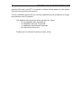
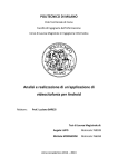
Figure 9 shows the protocol layers involved in the streaming in both elements: the
source (Server) and the receivers (Client). The protocol layers follow the standard of
OSI stack model.
Figure 9. Protocol Layers involved in the Streaming
21
Implementation of a Low Cost Video Wall using Raspberry Pi devices
2.1. Video Compression techniques
Video applications require some form of data compression to achieve reasonable
precondition for storage and transmission. The digital video compression is one of the
main issues in digital video coding, enabling efficient distribution and interchange of
visual information.
Video codecs are devices that are used to compress and decompress as well as to
encode and decode video streams. The most complex part of a codec is the
compress/decompress function. Codecs can do their work by hardware but also by
software with fast processors. The main goal of coding is the bit-rate reduction for
storage and transmission of the video source while retaining video quality as good as
possible. There are a number of international standards and also many proprietary
techniques for digital video compression. The basic idea behind video compression is
to remove spatial redundancy within a video frame and temporal redundancy between
adjacent video frames.
There are two main types of compression techniques, lossless and lossy. In the
lossless compression a frame can be decompressed into the original exactly. The
compression ratio of lossless methods (Huffman, Arithmetic, LZW, RLE) is not high
enough for digital video communication. In the lossy compression compressed data
that can be decompressed into images that look similar to the original (as human eye
sees them) is created, though they are different in digital form.
The human eye is more sensitive to changes in brightness than to chromaticity
changes. Therefore the image data is first divided into one luminance and two
chrominance components, and the chrominance components are subsampled relative
to the luminance component.
After this step the usual lossy compression method used in digital video compression is
based on Discrete Cosine Transform (DCT) and quantization. This technique reduces
the high spatial frequency components from the image since the human viewer is more
sensitive to the reconstruction errors of low frequency components.
The purpose of the quantization step is to represent the DCT-coefficients with the
precision what is needed to achieve the required image quality. The zig-zag step
arranges the high frequency coefficients to the end of the stream and since most of
them have become zero after the quantization, run length encoding (RLE) is used for
further compression.
The upper left corner coefficient represents the mean value of the block and is encoded
using the difference from the previous block (DPCM). The final step in the compression
process is to minimize the entropy using Huffman or arithmetic coding. The encoded
frame is often called I-frame (intra frame) because the encoding process uses no
information from other frames. The block diagram of the encoding process is
represented in Figure 10.
22
Implementation of a Low Cost Video Wall using Raspberry Pi devices
Figure 10. Block diagram of video compression
In addition to the previous compression technique, the temporal redundancy between
frames can be utilized for further compression. The basic method is to calculate the
prediction error between corresponding blocks in the current and previous frames. The
error values are then sent to the compression process. Compressed frames generated
using predictions are usually called P-frames. When using both previous and future
frames as reference, the frame is called B-frame (bidirectional frame).
Motion compensated prediction is an efficient tool to reduce temporal redundancy
between frames. The concept of motion compensation contains the motion estimation
between video frames (Figure 11). The motion is described by a small number of
motion vectors which gives the translation of a block of pixels between frames. The
motion vectors and compressed prediction errors are then transmitted.
Figure 11. Motion compensation
23
Implementation of a Low Cost Video Wall using Raspberry Pi devices
2.2. H.264 video codec
H.264/AVC8,, also known as MPEG-4, is the latest international video coding standard.
It was jointly developed by the ITU-T (International Telecommunication Union) “Video
Coding Experts Group” (VCEG) and the ISO/IEC (International Organization for
Standardization/ International Electrotechnical Commission) “Moving Picture Experts
Group” (MPEG).
The importance of new network access technologies like cable modem, xDSL (Digital
Subscriber Line) and UMTS created demand for the H.264/AVC11 standard. For this
reason, the goals of this standardization effort were enhanced compression efficiency
and network friendly video representation for interactive (video telephony) and noninteractive applications (broadcast, streaming10, storage and video on demand).
Therefore, H.264/AVC14 was designed to support a wide variety of applications and to
operate over several types of networks and systems. As a result, this standard
provides gains in compression efficiency of up to 50 % over a wide range of bit rates
and video resolutions compared to previous standards (H261, H263).
This video codec is used due to the project requeriments and, furthermore, it is
available on the frameworks to encode the video, and in the Raspberry Pi, to decode
the video.
2.2.1. Profiles and levels
The H.264/AVC standard defines profiles and levels in order to maximize the
interoperability while limiting the complexity. A profile is defined as a subset of coding
tools that can be used to generate a bitstream, whereas a level places constraints on
certain key parameters of the bitstream.
Therefore, by means of profiles and levels, minimum bounds on the decoding
capabilities can be set in order to target different application domains. Hence,
H.264/AVC defines different profiles. The ones listed below are the most important:
High: Primary profile for broadcast and disc storage applications, particularly for highdefinition television applications.
Baseline: Designed to minimize the complexity and provide high robustness and
flexibility, this profile is widely used in video conferencing and mobile applications.
Main: This profile typically allows the best quality at the cost of higher complexity and
delay.
Extended: This profile was designed to combine the robustness of the Baseline profile
with a higher degree of coding efficiency and greater network robustness for such
applications as flexible video streaming.
It is important to say that B slices are only allowed in the main profile and above. They
can be used to save on bandwitdth but are harder to decode, which is why some
devices might not support them.
All types of profiles have been tested, but the one used during the deployment of this
project has been High profile because it is adopted for high definition applications such
Blu-ray and DVB HDTV.
24
Implementation of a Low Cost Video Wall using Raspberry Pi devices
2.2.2. Structure
The H.264/AVC standard defines two conceptual layers: the “Video Coding Layer”
(VCL) and the “Network Adaptation Layer” (NAL). The first one defines the efficient
encoding representation of the video whereas the second one is designed to provide
“network friendliness” by facilitating the ability to map H.264/AVC VCL data to different
transport layers.
As in all prior ITU-T and ISO/IEC JTC1 (Joint Technical Committee 1) video standards
since H.261, the VCL design follows the so-called “block-based hybrid video coding
approach” in which each coded picture is divided into block-shaped units called
“macroblocks”. Each one of them consists of three components: Y, Cr and Cb, where Y
is the luminance component which represents brightness information and Cr and Cb
are the chrominances and represent the colour information. Due to the fact that the
human visual system is more sensitive to luminance than to chrominance, the
chrominance signals are both subsampled by a factor of 2 in horizontal and vertical
direction. Therefore, a macroblock consists of one block of 16x16 samples for the
luminance component and two blocks of 8x8 samples for the chrominance. This is
called 4:2:0 sampling with 8 bits of precision per sample.
These macroblocks are coded in Intra or Inter mode. Then, the prediction error, which
is the difference between the original and the predicted block, is transformed using a
4x4 integer transformation with similar properties as the 4x4 DCT (Discrete Cosine
Transform). The task of the transformation is to reduce the spatial redundancy of the
prediction error signal. As a result of the transformation, a block of transformed
coefficients is obtained which is next quantized using a “quantization parameter” (QP)
that can take up to 52 different values (0-51) when video format supports 8 bits per
decoded sample. Typically, the result is a block in which most or all the coefficients are
zero, with few non-zero coefficients.
The aim of the quantization process is to reduce the precision of the coefficients
according to the QP. If QP is set to a high value (the step size doubles with each 6
increments of QP), then more coefficients are set to 0 whereas if QP is set to a low
value, then more non-zero coefficients will remain after the process. Thus, this process
keeps the information from the low frequencies whereas the high frequencies are set to
0.
Next, the quantized transform coefficients of a block are generally scanned in a zig-zag
fashion and then transmitted using entropy coding methods. In H.264/AVC, two
methods of entropy coding are supported: a low complexity technique based on the
usage of contextadaptively switched sets of variable length codes (Context-Adaptive
Variable Length Coding (CAVLC)) and the algorithm of context-based adaptive binary
arithmetic coding (Context- Adaptive Binary Arithmetic Coding (CABAC)).
In order to reconstruct the same image on the decoder side, the dequantized
coefficients are inversed transformed and added to the prediction signal. The result is
the reconstructed macroblock.
A sequence of macroblocks is grouped together forming a “slice”. Therefore, a picture
is a collection of one or more slices in H.264/AVC. Moreover, slices are selfcontained
in the sense that the data within them can be correctly decoded without use of data
from other slices belonging to the same frame. As a consequence, in an IP network
environment each slice corresponds to a packet sent through the network.
25
Implementation of a Low Cost Video Wall using Raspberry Pi devices
2.3. Real Time Protocol Operation
2.3.1 What is RTP
RTP18 provides end-to-end network transport functions suitable for applications
transmitting real-time data, such as audio, video or simulation data, over multicast or
unicast network services; such as videoconferences. RTP does not address resource
reservation and does not guarantee quality of service for real-time services.
The use of this protocol is justified to transport information that requires a special
processing. This information must be available in real time for the receptor, and
therefore, must be strictly controlled to permit a correct reception.
It must be clarified that in all communications latency between receptor and transmitter
always exists. Depending on the applications, the requirements will be more or less
restrictive although all are real time applications. For example, online video
visualization through the Network is considerated a real time application because it
uses video and audio flows. The same occurs in videoconference applications. The
margins of second application are more restrictive.
In general and regarding real time applications, it is important to control the latency,
jitter and packet order arrival, as well as losses that might come, to ensure the
application proper functioning.
For all the reasons explained above, RTP fits perfectly with the project requirements to
be used as an application layer.
It is interesting to remark that RTP uses User Datagram Protocol (UDP) as a transport
layer. TCP (Transmission Control Protocol) is also a transport protocol that offers a
reliable video or audio stream but it will slow down transmission and re-transmit
corrupted packets in order to achieve that. On the other hand, UDP does not guarantee
the reliability of the communication and, therefore, will not slow down or re-transmit
data.
The application implemented in this project does not need a reliable data stream and,
in case of generating corrupted packets or losing any of them, the application does not
have a mechanism available for their retransmission. Therefore, UDP is a better
choice.
RTP functionalities will be explained in the next section.
26
Implementation of a Low Cost Video Wall using Raspberry Pi devices
2.3.2. RTP functions
The RTP protocol carries out a control task on media data flow adding, for example,
temporal marks and sequence numbers in each data packet to identify them in
reception. Furthermore, the protocol is capable of identifying transported information
according to the type (audio or video) and separate it in diverse flows. The principal
functions that can be performed using the RTP protocol are:
Calculating delays in communication
Temporal marks (timestamp) identify when data was sent and when it was received.
Synchronizing diverse flows if necessary
The temporal marks allow executing this synchronization (for example, an audio flow
associated to video).
Receiving the packets and processing in correct order
For this purpose, the sequence number is used. With it, it is possible to know which
one is the next packet to deal with, rearrange it if necessary and calculate the losses in
the system. In some cases, the sequence number is the only way to identify various
packets that can transport the same temporal mark (if the packet has been divided).
Finally, although it is not a specific protocol function, it is important to mention that this
does not contemplate the retransmission of data since there is no need to retransmit
information that cannot be used.
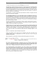
2.3.3. RTP packets and fields architecture
Below these lines, the RTP header is shown. The minimum RTP header size is 12
bytes (the fields marked in blue).
Figure 12. RTP Header format
The description of each of the fields in the header is the following:
27
Implementation of a Low Cost Video Wall using Raspberry Pi devices
Version Number (V) (2 bits)
Indicates the version of the protocol. The current version is 2.
Padding (P) (1 bit)
It is used to indicate if there are extra padding bytes at the end of the RTP packet.
Extension(X) (1 bit)
It indicates presence of an extension header between standard header and payload
data.
CSRC Count (CC) (4 bits)
Contains the number of Contributing Source identifiers that follow the fixed header.
Marker (M) (1 bit)
Marker bit. If progressive scan video is being transmitted, the marker bit denotes the
end of a video frame. If interlaced video is being transmitted, it denotes the end of the
field. The marker bit must be set to 1 for the last packet of the video frame/field. It must
be set to 0 for other packets.
Payload Type (PT) (7 bits)
A dynamically allocated payload type field.
Sequence Number (16 bits)
The low-order bits for RTP sequence number. The standard 16- bit sequence number
is augmented with another 16 bits in the payload header in order avoid problems due to
wrap-around when operating at high rate rates.
Time Stamp (32 bits)
For progressive scan video, the timestamp denotes the sampling instant of the frame to
which the RTP packet belongs. Packets must not include data from multiple frames,
and all packets belonging to the same frame must have the same timestamp.
Progressive scanning (alternatively referred to as noninterlaced scanning) is a way of
displaying, storing, or transmitting moving images in which all the lines of each frame
are drawn in sequence. This is in contrast to interlaced video used in traditional analog
television systems where only the odd lines, then the even lines of each frame (each
image called a video field) are drawn alternately. Progressive scanning is universally
used in computing.
For interlaced video, the timestamp denotes the sampling instant of the field to which
the RTP packet belongs. Packets must not include data from multiple fields, and all
packets belonging to the same field must have the same timestamp.
28
Implementation of a Low Cost Video Wall using Raspberry Pi devices
SSRC (32 bits)
Synchronization source identifier uniquely identifies the source of a stream.
The optional header extensions are described below:
Extended Sequence Number (16 bits)
The high order bits of the extended 32-bit sequence number, in network byte order.
Line No (15 bits)
Scan line number of encapsulated data, in network byte order. Successive RTP
packets may contain parts of the same scan line (with an incremented RTP sequence
number, but the same timestamp), if it is necessary to fragment a line.
Offset (15 bits)
Offset of the first pixel of the payload data within the scan line. If YCbCr format data is
being transported, this is the pixel offset of the luminance sample; if RGB format data is
being transported, it is the pixel offset of the red sample; if BGR format data is being
transported, it is the pixel offset of the blue sample. The value is in network byte order.
The offset has a value of zero if the first sample in the payload corresponds to the start
of the line, and increments by one for each pixel.
F (1 bit)
Field Identification identifies which field the scan line belongs to, for interlaced data.
F=0 identifies the first field and F=1 the second field. For progressive scan data (e.g.,
SMPTE 296M format video), F must always be set to zero.
Length (16 bits)
Numbers of octets of data included from this scan line, in network byte order. This must
be a multiple of the pgroup value.
C (1 bit)
Continuation determines if an additional scan line header follows the current scan line
header in the RTP packet. Set to 1 if an additional header follows, implying that the
RTP packet is carrying data for more than one scan line. Set to 0 otherwise.
Several scan lines may be included in a single packet, up to the path MTU limit. The
only way to determine the number of scan lines included per packet is to parse the
payload headers.
29
Implementation of a Low Cost Video Wall using Raspberry Pi devices
2.4. Real Time Control Protocol operation
This section aims to provide a global vision of RTCP operational (RFC 3550), their
functions and the packet types contemplated.
RTCP18 is introduced as an adjacent control protocol to the RTP. The RTCP
functionality is to report the network state to different nodes of communication.
As it is explained below, RTCP is a sister protocol of RTP and also it has been used in
this project during the streaming process to control and synchronize the audio and
video flows.
2.4.1. What is RTCP
RTCP provides out-of-band control information for an RTP flow. It is a sister protocol of
RTP and helps it in the delivery and packaging of multimedia data, but does not
transport any data itself. It is used periodically to transmit control packets to
participants in a streaming multimedia session. The primary function of RTCP is to
provide feedback on the quality of service being provided by RTP.
RTCP gathers statistics on a media connection and information such as bytes sent,
packets sent, lost packets, jitter, feedback and round trip delay. An application may use
this information to increase the quality of service, perhaps by limiting flow or using a
different codec.
This protocol does not offer itself any kind of response to any event on the network, but
it is a simple informant. The application layer will be the responsible for carrying out the
relevant actions.
2.4.2. RTCP functions
The RTCP protocol implements three different basic functionalities:
To provide information of transmission state and quality to the involve nodes
This is a totally necessary function for RTP transport protocol, to be able to implement
the flow control and congestion. Receiver and Sender Reports provide this information.
Implementation able to sync to various flows
This solves the problem that involves the use of the SSRC from the RTP protocol. This
field identifies every RTP flow avoiding confusion in the transmission. The same source
can define additional different flows (for example audio and video) with different SSRC.
Order to properly synchronize, RTCP use a new field called CNAME (canonical name)
identifying a single emitter. Can be associated diverse SSRC into same CNAME.
To realize the two previous functions, all RTP session nodes send RTCP packets. The
send tax of these packets should vary depending on number of participants in the
session, for optimal use of the network.
30
Implementation of a Low Cost Video Wall using Raspberry Pi devices
Session Control Information
Finally, RTCP can carry session control information. For example, it could carry
information regarding the participant identification and displayed to the user. The first
two functions must be met in all possible RTCP scenarios, but are especially important
in multicast sessions.
The sending of RTCP packets should be controlled
independently from the transmitter and receiver to avoid critical situations in
unidirectional channels where dialogue is impossible for the nodes.
2.4.3. RTCP fields and packets architecture
RTCP packet types defined according to their function and control information they
carry. Below, there is a brief summary:
Sender Report (SR)
This sends statistics information for receipt and transmission. Active transmitters send
them.
Receiver Report (RR)
This sends reception information statistics. No transmitters send them.
Source Description (SDES)
Identifies source, including CNAME.
End of participation (BYE)
It is a field that indicates the source disconnection.
Application-specific message (APP)
It indicates proper application functions.
All RTCP packets have a fixed part and other variable part that depending on the type,
have different length. This length must be a multiple of 32 bits. This is important
because several RTCP packets can be concatenated without any kind of separation to
form a bundle RTCP.
31
Implementation of a Low Cost Video Wall using Raspberry Pi devices
2.5. MPEG-2 Transmission
The MPEG-215 (Moving Picture Expert Group-2) standards define how to format the
various component parts of a multimedia program (which may consist of: MPEG-2
compressed video, compressed audio, control data and/or user data). It also defines
how these components are combined into a single synchronous transmission bit
stream. The process of combining the streams is known as multiplexing.
MPEG-2 has been used in this project to stream and receive correctly video flows
using a framework that only it allowed to handle this standard.
2.5.1. Building the MPEG Bit Stream
To understand how the component parts of the bit stream are multiplexed, we need to
first look at each component part. The most basic component is known as an
Elementary Stream in MPEG.
Elementary Stream
Each Elementary Stream (ES) output by an MPEG audio, video and some data
encoders contain a single type of signal.
For video and audio, the data is organized into access units, each representing a
fundamental unit of encoding. For example, in video, an access unit will usually be a
complete encoded video frame.
Packetized Elementary Stream
Each ES is input to an MPEG-2 processor which accumulates the data into a stream of
Packetized Elementary Stream (PES) packets. A PES packet may be a fixed or
variable sized block, with up to 65536 bytes per block and includes a 6 byte protocol
header. A PES is usually organized to contain an integral number of ES access units.
The PES header starts with a 3 byte start code, followed by a one byte stream ID and a
2 byte length field.
MPEG-2 Multiplexing
The MPEG-2 standard allows two ways of multiplexing16:
-
MPEG Program Stream: A group of tightly coupled PES packets referenced to
the same time base. Such streams are suited for transmission in a relatively
error-free environment and enable easy software processing of the received
data. This form of multiplexing is used for video playback and for some network
applications.
-
MPEG Transport Stream17: Each PES packet is broken into fixed-sized
transport packets forming a general purpose way of combining one or more
streams, possibly with independent time bases. This is suited for transmission
in which there may be potential packet loss or corruption by noise, or / and
where there is a need to send more than one program at a time.
32
Implementation of a Low Cost Video Wall using Raspberry Pi devices
Figure 13. Combining elementary streams from encoders into a TS or a PS
The Program Stream is widely used in digital video storage devices, and also where
the video is reliably transmitted over a network (e.g. video-clip download). Digital Video
Broadcast (DVB) uses the MPEG-2 Transport Stream over a wide variety of underlying networks. Since both the Program Stream and Transport Stream multiplex a set
of PES inputs and the interoperability between the two formats may be achieved at the
PES level.
2.5.2. MPEG Transport Stream
A transport stream consists of a sequence of fixed sized transport packet of 188 Bytes.
Each packet comprises 184 Bytes of payload and a 4 Bytes header. One of the items
in this 4 Byte header is the 13 bit Packet Identifier (PID) which plays a key role in the
operation of the Transport Stream.
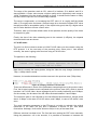
The format of the transport stream is described using the figure below. This figure
shows two elementary streams sent in the same MPEG-2 transport multiplex. Each
packet is associated with a PES through the setting of the PID value in the packet
header (the values of 64 and 51 in the figure). The audio packets have been assigned
PID 64, and the video packets PID 51 (these are arbitrary, but different values).
Figure 14. Single Program Transport Stream (Audio and Video PES)
As is usual, there are more video than audio packets, but we may also note that the
two types of packets are not evenly spaced in time. The MPEG-TS is not a time
division multiplex, packets with any PID may be inserted into the TS at any time by the
TS multiplexor. If no packets are available at the multiplexor, it inserts null packets
(denoted by a PID value of 0x1FFF) to retain the specified TS bit rate. The multiplexor
also does not synchronize the two PESs. A separate process is therefore required to
synchronize the two streams.
33
Implementation of a Low Cost Video Wall using Raspberry Pi devices
Transmission of the MPEG-TS
Although the MPEG TS may be directly used over a wide variety of media, it may also
be used over a communication network. It is designed to be robust with short frames,
each one being protected by a strong error correction mechanism. It is constructed to
match the characteristics of the generic radio or cable channel and expects an
uncorrected Bit Error Rate (BER) of better than 1010.
The MPEG-2 Transport Stream is so called, to signify that it is the input to the
Transport Layer in the ISO Open System Interconnection (OSI) seven-layer network
reference model. It is not, in itself, a transport layer protocol and no mechanism is
provided to ensure the reliable delivery of the transported data. MPEG-2 relies on
underlying layers for such services and the transport requires the underlying layer to
identify the transport packets, and to indicate in the transport packet header, when a
transport packet has been erroneously transmitted.
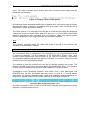
2.5.3. Format of a Transport Stream Packet
Each MPEG-2 TS packet carries 184 B of payload data prefixed by a 4 B (32 bit)
header.
Figure 15. MPEG-2 Transport Stream Header Description
The header has the following fields:
-
Synchronization Byte (8 bits). This has the bit pattern 0x47 (0100 0111).
Next, a set of three flag bits are used to indicate how the payload should be processed.
-
The first flag indicates a transport error.
The second flag indicates the start of a payload.
The third flag indicates transport priority bit.
The flags are followed by a 13 bit Packet Identifier (PID). This is used to uniquely
identify the stream to which the packet belongs (e.g. PES packets corresponding to an
ES) generated by the multiplexer. The PID allows the receiver to differentiate the
stream to which each received packet belongs. Some PID values are predefined and
are used to indicate various streams of control information. A packet with an unknown
PID, or one with a PID which is not required by the receiver, is silently discarded. The
34
Implementation of a Low Cost Video Wall using Raspberry Pi devices
particular PID value of 0x1FFF is reserved to indicate that the packet is a null packet
(and has to be ignored by the receiver).
The two scrambling control bits are used by conditional access procedures to encrypt
the payload of some TS packets.
-
Two adaption field control bits which may take four values:
- 01: No adaptation field, payload only.
- 10: Adaptation field only, no payload.
- 11: Adaptation field followed by payload.
- 00: Reserved for future use.
-
Finally there is a half byte Continuity Counter (4 bits).
35
Implementation of a Low Cost Video Wall using Raspberry Pi devices
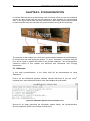
CHAPTER 3. FRAMEWORKS
During this project, there has been an investigation on different frameworks available to
form the video wall. The following are the four frameworks to focus on: GStreamer,
FFmpeg, VLC and OMXPlayer.
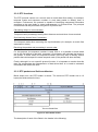
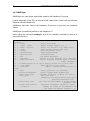
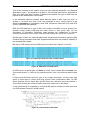
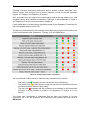
As a brief summary, the following table shows in which system component has been
used each framework:
Framework
GStreamer
FFmpeg
VLC
OMXPlayer
Server
Yes
Yes
Yes
No
Client
Yes
No
No
Yes
Function
Stream and receive audio and video flows.
Stream video flows.
Stream video flows.
Receive audio and video flows.
Table 3. Frameworks and components relationship
As it can be observed in the table above not all the frameworks are available for both,
server and client.
In this chapter the most relevant features of each one of these frameworks will be
described.
3.1. GStreamer
GStreamer18 is a library for constructing graphs of media-handling components. The
applications it supports range from simple Ogg/Vorbis playback, audio/video streaming
to complex audio (mixing) and video (non-linear editing) processing.
Applications can take advantage of advances in codec and filter technology
transparently. Developers can add new codecs and filters by writing a simple plugin
with a clean, generic interface.
Figure 16. GStreamer framework logo
GStreamer is released under the LGPL (Lesser General Public Licence).
The GStreamer main characteristics are:
Multiplatform
GStreamer has been ported to a wide range of operating systems, processors and
compilers. These include but are not limited to Linux on x86, PPC and ARM using
GCC. Solaris on x86 and SPARC using both GCC and Forte, MacOS X, Microsoft
Windows using MS Visual Developer, IBM OS/400 and Symbian OS.
36
Implementation of a Low Cost Video Wall using Raspberry Pi devices
GStreamer can bridge to other multimedia frameworks in order to reuse existing
components (e.g. codecs) and use platform input/output mechanisms:
-
Linux/Unix: OpenMAX-IL (via gst-omx)
-
Windows: DirectShow
-
Mac OS X: QuickTime
Comprehensive Core Library
-
Graph-based structure allows arbitrary pipeline construction.
-
Based on GLib 2.0 object model for object-oriented design and inheritance.
-
Compact core library of less than 500KB, about 65 K lines of code.
-
Multi-threaded pipelines are trivial and transparent to construct.
-
Clean, simple and stable API for both plugin and application developers.
-
Extremely lightweight data passing means very high performance/low latency.
-
Complete debugging system for both core and plugin/app developers.
-
Clocking to ensure global inter-stream synchronization (a/v sync).
-
Quality of service (QoS) to ensure best possible quality under high CPU load.
Intelligent Plugin Architecture
-
Dynamically loaded plugins provide elements and media types, demand-loaded via
a registry cache.
-
Element interface handles all known types of sources, filters and sinks.
-
Capabilities system allows verification of element compatibility using MIME types
and media-specific properties.
-
Auto plugging uses capabilities system to complete complex paths automatically.
-
Pipelines can be visualised by dumping them to a .dot file and creating a PNG
image from that.
-
Resource friendly plugins to do not waste memory.
Broad Coverage of Multimedia Technologies
GStreamer capabilities can be extended through new plugins. The features listed
below are just a rough overview of what is available using the GStreamer own plugins,
not counting any third party offerings.
-
Container formats: asf, avi, 3gp/mp4/mov, flv, mpeg-ps/ts, mkv/webm, mxf, ogg.
-
Streaming: http, mms, rtsp, rtp.
-
Codecs: FFmpeg, various codec libraries, 3rd party codec packs.
-
Metadata: native container formats with a common mapping between them.
-
Video: various colorspaces, support for progressive and interlaced video.
37
-
Implementation of a Low Cost Video Wall using Raspberry Pi devices
Audio: integer and float audio in various bit depths and multichannel configurations.
Extensive Development Tools
-
gst-launch command-line tool for quick prototyping and testing.
-
A lot of documentation, including partially completed manual and plugin writer's
guide.
-
Large selection of test programs and example code in each module.
-
Access to GStreamer API with various programming languages.
3.2. FFmpeg
FFmpeg47 is a free software project that produces libraries and programs for handling
multimedia data. FFmpeg includes libavcodec, an audio/video codec library used by
several other projects, libavformat, an audio/video container mux and demux library,
and the ffmpeg command line program for transcoding multimedia files. FFmpeg is
published under the GNU Lesser General Public License 2.1+ or GNU General Public
License 2+ (depending on which options are enabled).
Figure 17. FFmpeg logo
FFmpeg is the leading multimedia framework, able to decode, encode, transcode, mux,
demux, stream, filter and play a lot of formats. No matter if they were designed by
some standards committee, the community or a corporation. It contains libavcodec,
libavutil, libavformat, libavfilter, libavdevice, libswscale and libswresample which can be
used by applications. As well as ffmpeg, ffserver, ffplay and ffprobe which can be used
by end users for transcoding, streaming and playing.
The FFmpeg project tries to provide the best technically possible solution for
developers of applications and end users alike. To achieve this the best free software
options available are combined. They slightly favor their own code to keep the
dependencies on other libs low and to maximize code sharing between parts of
FFmpeg. Wherever the question of "best" cannot be answered both options are
supported so the end user can choose.
Security is a high priority, and code review is always done with security in mind.
Though due to the very large amounts of code touching untrusted data, security issues
are unavoidable. And thus they provide as quick as possible updates to the last stable
releases when new security issues are found.
Tools
FFmpeg provides various tools:
-
ffmpeg is a command line tool to convert multimedia files between formats.
38
Implementation of a Low Cost Video Wall using Raspberry Pi devices
-
ffserver is a multimedia streaming server for live broadcasts.
-
ffplay is a simple media player based on SDL and the FFmpeg libraries.
-
ffprobe is a simple multimedia stream analyzer.
Libraries
FFmpeg provides various developers libraries:
-
libavutil is a library containing functions for simplifying programming, including
random number generators, data structures, mathematics routines, core multimedia
utilities, and much more.
-
libavcodec is a library containing decoders and encoders for audio/video codecs.
-
libavformat is a library containing demuxers and muxers for multimedia container
formats.
-
libavdevice is a library containing input and output devices for grabbing from and
rendering to many common multimedia input/output software frameworks, including
Video4Linux, Video4Linux2, VfW, and ALSA.
-
libavfilter is a library containing media filters.
-
libswscale is a library performing highly optimized image scaling and color
space/pixel format conversion operations.
-
libswresample is a library performing highly optimized audio resampling,
rematrixing and sample format conversion operations.
39
Implementation of a Low Cost Video Wall using Raspberry Pi devices
3.3. VLC
VLC media player54 is a portable, free and open-source, cross-platform media player
and streaming media server written by the VideoLAN project. VLC media player
supports many audio and video compression methods and file formats, including DVDVideo, video CD and streaming protocols. It is able to stream over computer network
and to transcode multimedia files.
The default distribution of VLC includes a large number of free decoding and encoding
libraries, avoiding the need for finding/calibrating proprietary plugins. Many of VLC's
codecs are provided by the libavcodec library from the FFmpeg project, but it uses
mainly its own muxer and demuxers and its own protocols implementations. It also
gained distinction as the first player to support playback of encrypted DVDs on Linux
and OS X by using the libdvdcss DVD decryption library.
Figure 18. VLC Logotype
Because VLC is a packet-based media player, it plays almost all video content. It can
play some, even if they're damaged, incomplete, or unfinished. It also plays MPEG
transport streams (.TS) files.
VLC supports all audio and video formats supported by libavcodec and libavformat.
This means that VLC can play back H.264 or MPEG-4 Part 2 video as well as support
FLV or MXF file formats "out of the box" using FFmpeg's libraries. Alternatively, VLC
has modules for codecs that are not based on FFmpeg's libraries.
VLC has some filters that can distort, rotate, split, deinterlace, and mirror videos as well
as create display walls or add a logo overlay.
VLC can stream live, unencrypted content to a monitor or HDTV. VLC media player
can display the playing video as the desktop wallpaper, like Windows DreamScene, by
using DirectX, only available on Windows operating systems.
VLC can be installed or run directly from a USB flash drive or other external drive. VLC
can be extended through scripting. It uses the Lua scripting language. VLC can play
videos in the AVCHD format, a highly compressed format used in recent HD
camcorders. VLC can generate a number of music visualization displays. The program
is able to convert media files into various supported formats.
40
Implementation of a Low Cost Video Wall using Raspberry Pi devices
3.4. OMXPlayer
OMXPlayer is a video player specifically made for the Raspberry Pi devices.
It takes advantage of the GPU to decode H.264 videos and it comes with the standard
Raspbian Wheeze distribution.
OMXPlayer has been used in the Raspberry Pi devices to play back the streamed
videos.
OMXPlayer is installed by default on the Raspberry Pi.
When typing the command omxplayer, a list of the available command line options is
observed on screen.
Usage: omxplayer [OPTIONS] [FILE]
Options :
-h / --help
print this help
-n / --aidx index
audio stream index: e.g. 1
-o / --adev device
audio out device: e.g. hdmi/local
-i / --info
dump stream format and exit
-s / --stats
pts and buffer stats
-p / --passthrough
audio passthrough
-d / --deinterlace
deinterlacing
-w / --hw
hw audio decoding
-3 / --3d mode
switch tv into 3d mode (e.g. SBS/TB)
-y / --hdmiclocksync
adjust display refresh rate to match
video (default)
-z / --nohdmiclocksync do not adjust display refresh rate to match video
-t / --sid index
show subtitle with index
-r / --refresh
adjust framerate/resolution to
video
-l / --pos
start position (in seconds)
--boost-on-downmix
boost volume when downmixing
--subtitles path
external subtitles in UTF-8 srt form at
--font path
subtitle font
(default:/usr/share/fonts/truetype/
freefont/FreeSans.ttf)
--font-size size
font size as thousandths of screen height
(default: 55)
--align left/center
subtitle alignment (default: left)
--lines n
number of lines to accommodate in
the subtitle buffer (default: 3)
41
Implementation of a Low Cost Video Wall using Raspberry Pi devices
The following key commands do the following actions when pressed while playing a
video in OMXPlayer.
z
1
2
j
k
Show Info
Increase Speed
Decrease Speed
Previous Audio stream
Next Audio stream
i
o
Previous Chapter
Next Chapter
n
m
s
d
f
q
Space or p
Previous Subtitle stream
Next Subtitle stream
Toggle subtitles
Subtitle delay -250 ms
Subtitle delay +250 ms
Exit OMXPlayer
Pause/Resume
+
Decrease Volume
Increase Volume
Left Arrow
Right Arrow
Down Arrow
Up Arrow
Seek
Seek
Seek
Seek
-30
+30
-600
+600
42
Implementation of a Low Cost Video Wall using Raspberry Pi devices
CHAPTER 4. MILESTONES
This chapter will describe the different milestones defined in this project and how they
are achieved by using the different frameworks available.
The work methodology employed is the following:
1. Defining the deployment scenarios.
2. For each scenario, defining different milestones.
3. For each milestone, trying to implement a solution using the available frameworks.
4. Translation of each milestone pipeline to C code.
4.1. Deployment scenario 1
The deployment scenario 1 is the following:
Figure 19. Deployment scenario 1
The scenario is composed by the Raspberry Pi, a keyboard and one monitor screen. In
this scenario, the following milestones will be performed:
-
Play back a H.264 Full HD Video.
43
Implementation of a Low Cost Video Wall using Raspberry Pi devices
4.1.1. Milestone 1 - Playing back a H.264 Full HD Video
GStreamer
After some investigation and testing, how to create a pipeline able to play back a H.264
1080p video was discovered:
gst-launch-1.0 filesrc location= /home/pi/Monsters.mp4 ! qtdemux
name=dmux dmux.video_0 ! queue ! decodebin ! autovideosink
dmux.audio_0 ! queue ! aacparse ! faad ! alsasink
The description of this pipeline is simple. The command gst-launch-1.020 allows us to
access the Gstreamer command-line tool for quick prototyping and testing interface.
The next element, filesrc location, allows the reading of data from a file in the local file
system. The path of the file needs to be specified.
The element ! is used for linking the file to the next element, in this case the qtdemux
(Quicktime demuxer). Qtdemux demultiplex a file into audio and video streams. A
name for the demuxer has to be specified. In this case the name is dmux. At this point,
each part of the stream has to be linked to other elements that will decode and print
them on the screen.
To indicate the command of dealing with the video stream dmux.video_0 is written.
This specifies that we will treat now with the video part only. The video stream is linked
to a queue by the element !. The queue will create a new thread to handle this part of
the stream. To decode the video the information stored in the queue will be linked to
the element decodebin by using !. decodebin is an auto-plugin to decode raw-media.
It is a container for a collection of elements, in this case, decoders. Essentially, this
element will find the correct decoder to decode the video stream. Once the video is
decoded the result is linked to the element which will print out the video on the screen,
by using !. The element responsible of it is autovideosink. It detects an appropriate
video sink to use.
Having coped with the video stream, the audio stream remains to be handled. To deal
with the audio stream dmux.audio_0 has to be added next to autovideosink without !
since autovideosink is not to be linked to another element. This indicates that we want
to treat the audio stream. The audio stream is linked to a new queue that will create a
thread to handle in parallel the audio part. The next step is to link this to the element
aacparse which is a parser for Advanced Audio Coding that handles both ADIF and
ADTS stream formats. The audio is now ready to be decoded. GStreamer has an AAC
decoder element called Free – Advanced Audio Decoder (faad) in charge of decoding
aac audio format. Finally the result of the decoder needs to be linked to the element
alsasink. This element provides an output to a sound card via ALSA.
44
Implementation of a Low Cost Video Wall using Raspberry Pi devices
FFmpeg
Due to there is no HW Support of FFmpeg in the Raspberry Pi, it was decided to use
the GStreamer and OMXPlayer reception to play back the videos on the Raspberry Pi.
The same reason applies to the rest of reception milestones in this chapter.
VLC
There is HW Support of VLC in the Raspberry Pi60 but due to the complexity and the
constant request of multiple third party libraries, this option was impossible to
implement. 2 days (7 hours per day) were devoted to it but the compilation failed. All
the installation details are explained in Annex C. The final decision was to use the
GStreamer and OMXPlayer reception to play back the videos on the Raspberry Pi.
OMXPlayer
The following pipeline plays back nicely a Full HD video stored in the Raspberry Pi
device. The audio is outputted through the speakers connected to the Raspberry Pi
device.
omxplayer Monsters.mp4
45
Implementation of a Low Cost Video Wall using Raspberry Pi devices
4.2. Deployment scenario 2
The deployment scenario 2 is the following:
Figure 20. Deployment scenario 2
The scenario is composed by a computer that will act as a server, an Ethernet Cat 5e
cable to connect the computer with the Raspberry Pi, a HDMI cable and a monitor
screen.
In this scenario, the following milestones will be performed:
- Sending a HD/Full HD video to one Raspberry Pi.
- Sending a real time web cam video flow to one Raspberry Pi.
- Receiving a Full HD video / WebCam and playing back.
- Sending a Full HD video using MPEG-2 TS.
- Receiving a Full HD video using MPEG2-TS.
46
Implementation of a Low Cost Video Wall using Raspberry Pi devices
4.2.1. Milestone 2 - Sending a HD/Full HD video to one Raspberry Pi
GStreamer
The aim is to find out how to stream a H.264 Full HD video over the network using the
RTP protocol.
gst-launch-1.0 filesrc location=Videos/Monsters.mp4 ! qtdemux
name=dmux dmux.video_0 ! queue ! rtph264pay config-interval=1 !
udpsink host=192.168.137.3 port=5002 dmux.audio_0 ! queue !
aacparse ! faad ! alsasink
The aim is to describe only the new elements that appear above since most of them
are described in Milestone 1.
The procedure is to separate the video stream and the audio stream and then
encapsulate them into RTP packet. After, stream them using UDP to the receiver. The
audio is playing in local because the faad element belongs to bad-plugins and its
behaviour when receiving the audio stream through the network was unpredictable. For
this reason it was decided to play back the audio in local, to avoid troubles.
As it can be observed, the pipeline starts as in Milestone 1. Once the video stream is
demultiplexed it is encapsulated into RTP container.
rtph264pay needs to be configurated with a config-interval=1 to send the SPS
(Sequence Parameter Set) and PPS (Picture Parameter Set) every 1 second so that
the application can decode the content that is coming in. It is a very important
parameter. Without indicating a config-interval, the receiver is not able to decode the
stream. Chapter 5 explains SPS and PPS in detail.
Finally, the element udpsink is the UDP packet sender that sends data over our
network via UDP. The destination IP address and the port to send the packets to have
to be indicated.
FFmpeg
1. HD video
The aim is to find out how to stream a H.264 HD video over the network using the RTP
protocol.
ffmpeg -re -i /home/carlos/Descargas/HD/Serenity.mp4 -vcodec
libx264 -tune zerolatency -preset superfast -an -f rtp
rtp://192.168.137.3:5002
47
Implementation of a Low Cost Video Wall using Raspberry Pi devices
To begin writing a pipeline the command ffmpeg has to be used.
The parameter –re allows ffmpeg to read input at native frame rate. It is mainly used to
simulate a grab device or live input stream (e.g. when reading from a file). Should not
be used with actual grab devices or live input streams (where it can cause packet loss).
By default ffmpeg attempts to read the input(s) as fast as possible. This option will slow
down the reading of the input(s) to the native frame rate of the input(s). It is useful for
real-time output (e.g. live streaming).
The parameter –i is used to specify the input format file or device. The path of the file
that is to be streamed is indicated.
The parameter –vcodec will set the video codec used for encoding the video file. In
this case libx26450 is used. It is a free software library and application for encoding
video streams into the H.264/MPEG-4 AVC compression format, and is released under
the terms of the GNU GPL. Then two parameters are added (speed-preset and tune,
which are exactly the same as GStreamer). The process of decoding and encoding is
done when the library is called.
The step of decoding and re-encoding the video could be omitted with the option –
vcodec copy which only will demux and mux. This could be very useful to reduce CPU
usage in the server as happens with GStreamer.
Following this way, the output stream does not work with the reception pipeline and
nothing is shown on screen. After a lot of testing trying to obtain the same result as
GStreamer, all the attempts are unsuccessful. The problem remains in the transmission
of SPS and PPS messages. In FFmpeg captures with Wireshark messages are not
seen. Once the video is re-encoded, the SPS and PPS messages appear in the
capture.
Next to it, the parameter –an is indicated to skip audio.
Finally, the indication of the output file (-f) is required. In this case, the output of the
encoded stream must be encapsulated over RTP52 and sent to the IP and port
indicated in the pipeline.
When the pipeline is executed the following informations appears on the screen:
Figure 21. FFmpeg statistics Milestone 1
Here some interesting information is observed. First of all, FFmpeg is saying which
frame is now streaming. Secondly, it provides information about the frame rate. In this
example, the video has been previously analyzed and it is known that its frame rate is
24 fps. Hence, FFMpeg is streaming the video with a correct frame rate.
Then FFmpeg provides us the parameter q=23. This is related to the Constant Rate
Factor (CRF). CRF allows the encoder to achieve a certain output quality for the whole
file when output file size is of less importance. This provides maximum compression
efficiency with a single pass. Each frame gets the bitrate it needs to keep the requested
quality level. The downside is that it is not possible to tell FFmpeg to get a specific file
size or not to go over a specific size or bitrate.
48
Implementation of a Low Cost Video Wall using Raspberry Pi devices
The range of the quantizer scale is 0-51: where 0 is lossless, 23 is default, and 51 is
worst possible. A lower value means a higher quality and a subjectively sane range is
18-28. Considered 18 to be visually lossless or nearly, it should look the same or nearly
the same as the input but it is not technically lossless.
The range is exponential, so increasing the CRF value +6 is roughly half the bitrate
while -6 is roughly twice the bitrate. General usage is to choose the highest CRF value
that still provides an acceptable quality. If the output looks good, then try a higher value
and if it looks bad then choose a lower value.
Therefore, here q=23 means default value of the quantizer and the quality of the video
in reception is good.
Finally, the size of the video streaming sent to the network (in KBytes), the elapsed
time and the bit rate are shown.
2. Full HD video
The aim is to find out how to stream a H.264 Full HD video over the network using the
RTP protocol. It is the next step of the previous point. Since point 1 has worked
correctly, the same is going to be done but using a Full HD video.
The pipeline is the following:
ffmpeg -re -i /home/carlos/Descargas/FullHD/Monsters.mp4 -vcodec
libx264 -tune zerolatency -preset superfast -an -f rtp
rtp://192.168.137.3:5002
Note that it is exactly the same pipeline, being the video the only change (instead of a
720p, a 1080p video is used).
However, the results obtained are not the same as in the previous case (720p video):
Figure 22. FFmpeg statistics Full HD video
There are differences in some of the parameters comparing them to the previous case.
First, the bit rate increases much compared to the previous case (HD), which is normal
because it is Full HD video, whose avarage bit rate is usually between 8 and 12 Mbps.
On the contrary, the bit rates of the HD videos fluctuate between 3 and 5 Mbps.
The maximum peek is not reflected on the two different pictures above, though peeks
about 11 Mbps, in the case of Full HD videos, and 5 Mbps, in case of HD videos, were
seen.
The most interesting parameter is that FFmpeg is not able to maintain the original
frame-rate of the video (24 fps) and it maintains it around 13 fps, with some
fluctuations. Although, it has never arrived to 24 fps in any of the tests done.
Different solutions has been tried. The first has been setting the CRF value manually.
Using the parameter –crf in the encoder, it is possible to decrease or increase the
49
Implementation of a Low Cost Video Wall using Raspberry Pi devices
value. The value increases up to 28 (the limit value inside the sane range) and the
results are the following:
Figure 23. FFmpeg statistics (CRF applied)
As expected, bitrate decreases and the fps increases but it is still not enough to fluently
play back the video in reception. Increasing CRF up to insane value, correct fps rate is
achieved but quality becomes a disaster.
The other ‘solution’ is to manually fix the bit rate to certain amount using the parameter
–b and the maximum bitrate value. After trial and error, it is found that around 2500
Kbit/s bit rate the fps value increases up to 24. However, again, this reduces quality
and the visualization is not as good as with the GStreamer emmiter.
VLC
The following command takes the video and sends it directly to the receiver. No
decoding or re-encoding is needed.
cvlc Serenity.mp4 --sout '#rtp{ dst=192.168.137.3,port-video=5002}'
The command is easy to understand: cvlc (command vlc) is the command that allows
to create the pipelines. The first parameter is the video file to stream. Then –sout
(stream output) indicates the type of output (in our case RTP protocol). Furthermore
the destination address and the video port are indicated. The receiver is listening to the
same IP and port to play back the stream.
The problem is that the receivers are not able to decode perfectly the stream. The
stream is printed in the screen but errors during the visualization occur. The reception
is done using the GStreamer pipeline defined in Milestone 4 in this chapter.
Investigating some Wireshark captures were taken and it was discovered that
PPS/SPS were not sent periodically and even more, no trace of I, P and B frames
appeared in the capture. Instead of them, some mark undefined packets appeared, as
in figure 24. Deeper analysis of Wireshark captures is described in chapter 5.
Figure 24. Mark undefined packets – VLC
An effort was made in order to send a Full HD video using the same pipeline but quality
playback in reception was very low.
50
Implementation of a Low Cost Video Wall using Raspberry Pi devices
4.2.2. Milestone 3 - Sending a real time web cam video flow to one Raspberry
Pi
This milestone has been implemented only with GStreamer framework.
The aim is to find out how to stream a WebCam video flow from the server to the client.
The resolution of the server web cam is 640x480.
gst-launch-1.0 v4l2src ! 'video/x-raw, format=YUY2, width=640,
height=480' ! x264enc tune="zerolatency" speed-preset=2 ! queue
! rtph264pay ! udpsink host=192.168.137.3 port=5002
The goal is to describe only the new elements since most of them are described in
Milestone 1 and 2.
A new element that appears here is v4l2src. This element reads frames from a
Video4Linux2 device. A web cam is a type of v4l2src so this element sets up the
webcam and reads frames from it. The features of the web-cam have to be linked to
the element. In this case, the web-cam generates unstructured and uncompressed raw
video data using format YUY2 Video picture encoding, with a resolution of 640x480.
The format of the Web Cam video is not H.264 so encode needs to be done using the
element x264enc.
x264enc is the H.264 encoder. Some parameters have been set to it. One of them is
speed-preset. That is the preset name for speed/quality trade-off options (taking into
account that can affect decode compatibility). In this case this option is set to the value
2, which means super-fast. In case of having a better server this parameter can be
switched to value 3-4. If value 3 is used in the server the CPU usage increases up to
90% and saturates so, speed-preset with value 2 becomes the better value to use.
The second parameter of x264enc is tune. Its value is zerolatency. Reducing x264's
latency is possible, but reduces quality. Since latency in the encoder is not wanted, this
parameter is set up.
51
Implementation of a Low Cost Video Wall using Raspberry Pi devices
4.2.3. Milestone 4 - Receiving a Full HD video / WebCam and playing back
This milestone has been implemented only with GStreamer framework.
This pipeline describes the inverse process done in Milestones 2 and 3. The aim is to
decode the H.264 encoded video in the server and play it back in the receiver without
latency and without reducing quality.
gst-launch-1.0 udpsrc uri=udp://192.168.137.3:5002
caps="application/x-rtp, clock-rate=90000, payload=96" !
rtpjitterbuffer latency=500 ! rtph264depay ! decodebin !
autovideosink
The aim is to describe only the new elements that appear here since most of them are
described in Milestone 1, 2 and 3.
In this pipeline udpsrc29 appears as a first element. It receives specified data over the
network via UDP from the IP and port. A parameter called caps is added to udpsrc.
The first caps parameter indicates that the type of content is RTP, then clock-rate and
payload type refers to RTP audio video profile (RTP/AVP). A clock-rate of 90000 and
payload type equal to 96 refer to H.264 default payload type.
The next element is rtpjitterbuffer that is responsible of dealing with network jitter and
other transmission faults. The rtpjitterbuffer will wait for missing packets up to a
configurable time limit using the latency property.The default latency is set to 150 ms.
For Full HD videos the value needs to be increased up to 500 ms.
Then the element rtph264depay (RTP H.264 depayloader) will be used to extract
H.264 video from RTP packets.
Finally, it is important to comment that the decodebin element will find the appropriate
decoder for the H.264 video. It will find the decoder omxh264dec, the GStreamer
plugin that allows H.264 hardware decoding using Raspberry Pi.
52
Implementation of a Low Cost Video Wall using Raspberry Pi devices
4.2.4. Milestone 5 - Sending a Full HD video using MPEG-2 TS
GStreamer
The aim of this pipeline is to be able to send the video using a RTP MPEG-2 TS
container. When done, it will be possible to use this project for other types of receivers
that use this type of container.
gst-launch-1.0 filesrc location= Descargas/FullHD/Monsters.mp4 !
decodebin ! x264enc speed-preset=2 tune=zerolatency ! video/xh264 ! mpegtsmux ! rtpmp2tpay ! udpsink host=192.168.137.3
port=5002
The main point is to describe only the new elements that appear here since most of
them are described in the previous milestones.
The idea is the same as the one shown in Milestone 2. In this case a RTP payloader
that does not allow setting a config-interval is used to send periodically SPS and PPS
frames. To avoid the problem, decode and re-encode must be done. It is a nonsensical
step, though it is mandatory in order to decode the video in our Raspberry Pi devices.
After defining the location of the video, it is decoded using decodebin element and reencoded again using the x264enc element. This will increase the CPU usage much
because decode and encode do need it.
Another new element is mpegtsmux. It multiplexes media streams (in this case, it will
mux video and audio streams) into an MPEG Transport Stream. The type of video must
be indicated (in this case, video/x-h264). This element adds latency to the stream.
Finally, as commented above, rtpmp2tpay encapsulates payload MPEG2 TS into
RTP packets.
VLC
The same idea as in GStreamer case is followed now. Using the GStreamer pipeline
shown in Milestone 6, the results obtained were very low quality playback in reception
(errors appeared in the video playback).
cvlc Serenity.mp4 --sout '#rtp{dst=192.168.137.3, port=5002, mux=ts}'
After some research, it was found that the problem might be due to SPS/PPS.
SPS/PPS had to be related to the use of SDP files, in which transmission parameters
could be defined.
A SDP (Session Description protocol) file was created and attached to the command.
Here is the command line used to include the SDP file:
cvlc Serenity.mp4 --sout '#rtp{dst=192.168.137.3, port=5002,
mux=ts, sdp=file://home/carlos/File.sdp}'
53
Implementation of a Low Cost Video Wall using Raspberry Pi devices
The results obtained with VLC were not satisfactory, even using the SDP file.
4.2.5. Milestone 6 - Receiving a Full HD video using MPEG2-TS
GStreamer
This pipeline describes the inverse process done in Milestone 5. The aim is to decode
the H.264 video over RTP MPEG2-TS container encoded in the server and play it back
in the receiver without reducing quality.
gst-launch-1.0 udpsrc uri=udp://192.168.137.3:5002
caps="application/x-rtp, clock-rate=90000, payload=96" !
rtpjitterbuffer latency=500 ! rtpmp2tdepay ! decodebin !
autovideosink
The new element here is the rtpmp2tdepay that extracts MPEG2-TS from RTP
packets.
OMXPlayer
OMX player is only able to play back video streams that use MPEG2-TS container. To
receive the stream the following pipeline has to be typed:
omxplayer udp://192.168.137.3:5002
The emmiter pipeline used is the one described in Milestone 5 (GStreamer).
The video stream was not played back correctly. Video errors appeared on the screen.
The log files and Wireshark captures of each of the milestones were printed in order to
find out the differences. After analyzing them, it was discovered that the local video had
no B frames while the streamed video did.
It was then decided to remove B frames from the streamed video. However, the results
were not satisfactory. A deeper investigation should be done in order to find out the
correct way to stream the video with GStreamer to be received correctly by
OMXPlayer.
54
Implementation of a Low Cost Video Wall using Raspberry Pi devices
4.3. Deployment scenario 3
The deployment scenario 3 is the following:
Figure 25. Deployment scenario 3
This is the first deployment scenario in which the audio will be streamed and
processed. In the figure above the speaker is connected to the Raspberry Pi device
using a 3.5 mm jack to provide the stereo audio.
The following milestones will be performed in this deployment:
- Extracting and sending the audio stream from a 1080p video
- Receiving and playing back the Full HD audio stream
55
Implementation of a Low Cost Video Wall using Raspberry Pi devices
4.3.1. Milestone 7 - Extracting and sending the audio stream from a Full
HD video
This milestone has been implemented only with GStreamer framework.
As commented in Milestone 2, some problems with audio stream appeared. After
investigating, it was found how to stream the audio contained in a Full HD video
correctly. The pipeline able to do it is the following:
gst-launch-1.0 filesrc location=Videos/DesMe2.mp4 ! qtdemux
name=dmux dmux.audio_0 ! queue ! decodebin ! audioconvert !
audio/x-raw ! rtpL16pay ! udpsink host=192.168.137.3 port=6000
This pipeline uses qtdmux for demultiplex the video file into audio. The audio stream
will be handled and decoded. Once it is decoded, the aac audio will be converted to
‘raw audio’ using the element audioconvert . This element converts audio into different
formats. Finally, RTP L16 Payloader encapsulates raw audio into RTP packets
according to RFC 3551 (RTP Profile for Audio and Video Conferences with Minimal
Control).
4.3.2. Milestone 8 - Receiving and playing back the Full HD audio stream
This milestone has been implemented only with GStreamer framework.
The inverse process of Milestone 7 is achieved using the following pipeline:
gst-launch-1.0 udpsrc uri=udp://192.168.137.3:6000 !
"application/x-rtp,media=(string)audio, clock-rate=(int)96000,
encoding-name=(string)L16, payload=(int)96" ! rtpjitterbuffer !
rtpL16depay ! audioconvert ! alsasink
To receive the audio the element udpsrc is used and a set of caps parameters need to
be used indicating that what it will received is a RTP application which contains audio
media, with a clock-rate of 96000, encoded using L16 container and with payload value
96. Then the rtpjitterbuffer is used and we decapsulate the audio stream using the
element rtpL16depay. We convert the audio stream to the one suitable for the audio
output (alsasink).
56
Implementation of a Low Cost Video Wall using Raspberry Pi devices
4.4. Deployment scenario 4
The deployment scenario 4 is the following:
Figure 26. Deployment Scenario 4
This is the last deployment scenario that combines all the previous ones. It is
composed by the server, a router to forward the audio and video flows to the
corresponding Raspberry Pi device and monitor screens and speakers to visualize the
video and listen to the audio.
In this scenario, the following milestones will be performed:
-
Splitting and sending Full HD video to Raspberry Pi devices
-
Receiving a Full HD/Cam and playing back / cropping the video
57
Implementation of a Low Cost Video Wall using Raspberry Pi devices
4.4.1. Milestone 9 - Splitting and sending Full HD video to Raspberry Pi
devices
GStreamer
In this case there are 2 Raspberry Pi, each one connected to a different monitor
screen. In addition a router (or switch) is needed in between to send two video flows
(one to each Raspberry). It is necessary because our server only has one Ethernet
port.
The aim of the pipeline defined below is to split the video into two different video flows
and send them to the respectively Raspberry Pi devices. The two Raspberry Pi devices
will use the pipeline defined in Milestone 4.
gst-launch-1.0 filesrc location=Descargas/FullHD/WalkingDead.mp4
! qtdemux name=dmux dmux.video_0 ! queue ! decodebin ! tee
name=t ! queue ! videocrop right=960 bottom=312 ! x264enc
speed-preset=2 tune=zerolatency ! rtph264pay config-interval=1 !
udpsink host=192.168.137.4 port=5004 t. ! queue ! videocrop
left=960 bottom=312 ! x264enc speed-preset=2 tune=zerolatency !
rtph264pay config-interval=1 ! udpsink host=192.168.137.5
port=5005 dmux.audio_0 ! queue ! aacparse ! faad ! alsasink
The pipeline starts, as usual, defining the video that will be streamed to the network.
The element qtdemux demultiplex the video file into audio and video streams. The
video stream will be handled and decoded. It is mandatory to decode in oder to apply
video filters.
Since the video flow has to be duplicated to be sent to two different receivers, the
element tee with name t is needed. This element splits data to multiple branches.
Branching the data flow is useful when capturing a video shown on the screen and also
encoded and written to a file or need to be streamed through the network.
The next step is to crop the video. A queue generates a thread that will handle the split
part of the stream. The next element, videocrop (a video filter), can remove parts of
the picture on the left, right, top or bottom and output a smaller picture than the input
one without the unwanted parts of the border.
In the case of having a 1920x1080p video, four videos with a resolution of 960x540 are
needed to maintain the original aspect ratio. This will allow visualizing each part of the
video in Full Screen in the corresponding monitor. Due to there are only 2 Raspberry Pi
devices available, the video wall can only be performed with 2 monitor screens.
Scalability is possible. For instance, if there were 9 Raspberries it should be possible to
implement a video wall of 3x3. The only need is to crop the corresponding part of the
58
Implementation of a Low Cost Video Wall using Raspberry Pi devices
original video for each Raspberry. Obviously, the server must have better features than
the ones used in this project.
Figure 27. Video cropping example
Now decoding is done using the H.264 encoder and the first video stream is
encapsulated and sent through the network.
Exactly the same is done in parallel for the other part of the video. The element t is
used to separate the two video flows contained in the same pipeline.
CPU usage will increase due to decoding and re-encoding process. It is mandatory to
decode and re-encode because when applying a video filter such as a videocrop, the
flow must be decoded. Then, once the video filter is applied, re-encode must be done
again so that the Raspberry Pi device decodes the stream and shows it on the screen.
The difference in CPU usage between Milestone 2 and Milestone 7 is huge but it is due
to this intermediate step.
Two alternative ways are possible in order to avoid high CPU usage.
The first one is to pre-crop all the parts of the video using GStreamer. In this case it
would be very easy to send all the different flows and the CPU usage would be very
low compared with the actual case. The issue of this option is that cropping a video
might take a lot of time depending on its length.
The second way is to crop the videos in the Raspberry Pi devices. This method will
increase the CPU usage in the receivers. How to crop in the receivers is explained in
Milestone 10.
59
Implementation of a Low Cost Video Wall using Raspberry Pi devices
FFmpeg
The aim of the pipeline defined below is to split the video into two different video flows
and send them to the respective Raspberry Pi devices.
It is important to say that when using a Full HD video, instead of HD video, the same
problem that in Milestone 2 happened. The fps ratio was not enough so this pipeline
had to be used with 720p videos.
ffmpeg -re -i /home/carlos/Descargas/HD/Serenity.mp4 -vcodec
libx264 -tune zerolatency -preset superfast -map 0:0 -vf
"crop=640:360:0:0" -an -f rtp rtp://192.168.137.4:5004 -vcodec
libx264 -tune zerolatency -preset superfast -map 0:0 -vf
"crop=640:360:640:0" -an -f rtp rtp://192.168.137.5:5005
This pipeline is similar to the ones explained in milestone 2. The focus will be on the
new elements.
The element -map is mapping the input stream to the output stream.
The element –vf (video filter) creates a filter graph specified by the input parameter (in
our case “crop=640:360:0:0”) and uses it to filter the stream. The parameter indicates
that a section of 640x360 pixels is to be cropped in position x=0, y=0. In the second
part of the stream the same will be done in position x=640, y=0. When applying these
two crops, the first and the second quarters (half of the video) are obtained and sent to
the corresponding Raspberry Pi device.
The rest of the elements have been explained in Milestone 2.
It is observed that rame rate is maintained constant to 24 fps and bit rate decreases
with respect Milestone 2.
Figure 28. FFmpeg statistics
60
Implementation of a Low Cost Video Wall using Raspberry Pi devices
4.4.2. Milestone 10 - Receiving a Full HD/Cam and playing back / cropping
the video
This milestone has been implemented only with GStreamer framework.
The pipeline is very similar with to one described in Milestone 4.
gst-launch-1.0 udpsrc uri=udp://192.168.137.4:5004
caps="application/x-rtp, clock-rate=90000, payload=96" !
rtpjitterbuffer latency=500 ! rtph264depay ! decodebin ! queue !
videocrop left=960 bottom=540 ! autovideosink
After decoding the video, it is possible to apply videofilters and, in this case, the
element videocrop was applied. The result is outputted to the autovideosink element
that will display the cropped video.
As commented before, in Milestone 9, this new step implies higher CPU usage in the
Raspberry Pi. In chapter 6, the CPU usage obtained results are commented.
Raspberry Pi can only handle Full HD video flows. Therefore, if higher resolution
videos (2K, 4K) were to be cropped, this method would not work because Raspberry Pi
would not be able to decode them. In the case of 2K or 4K videos, the best choice is to
use the Pipeline defined in Milestone 9 using a server with a better CPU than the one
used in this project.
4.4.3. Milestone 11 - Combining Milestone 2 and Milestone 7
This milestone has been implemented only with GStreamer framework.
The idea is to be able to send video and audio stream together and synchronized. In
order to do this, we need to combine Milestone 2 and Milestone 7. The resulting
pipeline is the following:
gst-launch-1.0 filesrc location=Videos/Monsters.mp4 ! qtdemux
name=dmux dmux.video_0 ! queue ! rtph264pay config-interval=1 !
udpsink host=192.168.137.255 port=50000 dmux.audio_0 ! queue !
decodebin ! audioconvert ! audio/x-raw ! rtpL16pay ! udpsink
host=192.168.137.3 port=5003
Here is the final pipeline obtained that sends the H.264 Full HD video flow in broadcast
to all the Raspberry Pi devices in the scenario. The Raspberry Pi devices will decode
the stream using the pipeline defined in Milestone 10. Each one of them will have a
different value to crop the video.
An extra Raspberry Pi will be needed to play back the audio stream. In the above
pipeline the user will indicate the IP address of the Raspberry Pi device that will handle
audio stream. When testing a Raspberry Pi device to play back Full HD video and
audio at the same time and it worked with some difficulties.
Therefore, to avoid problems, it is recommended to use one extra Raspberry to handle
the audio stream perfectly. The pipeline for handling the audio stream in the Raspberry
is defined in Milestone 8. It is necessary to remark that the CPU usage of this pipeline
61
Implementation of a Low Cost Video Wall using Raspberry Pi devices
is similar to the one defined in Milestone 2. For this reason it is not taken into account
in the CPU comparison in chapter 6.
4.5. Translation of GStreamer Pipelines to C Code
GStreamer pipelines created in different milestones have been translated to C Code.
The advantages of writting the code in C are that the programs run quickly because
they can access low level facilities (both, in the Raspberry and in the server).
To compile the programs created, the following command is needed:
gcc -Wall program.c -o program $(pkg-config --cflags --libs gstreamer-1.0)
In the example above a program called program.c is being compiled. GStreamer
makes use of pkg-config to get compiler and linker flags needed to compile this
application.
We can run the application by using ./program.
62
Implementation of a Low Cost Video Wall using Raspberry Pi devices
CHAPTER 5. SYNCHRONIZATION
In a Video Wall the idea of synchronizing a set of screens is that you can use individual
content on each screen but still get the monitors to work together in a synchronized
way. In the figure below there are three animations (video clips) that are synchronized
to start simultaneously and maintain this synchronization during all the streaming.
Figure 29: Video Wall syncronization example
The purpose of this chapter is to verify the synchronization between the two Raspberry
Pi devices that are used during the project. To do so, Wireshark, a network analyzer
tool, will be used to explain the basis of the packets captured. The synchronization
evidences shown in this chapter are achieved with GStreamer and FFmpeg
frameworks.
5.1. GStreamer
In this case synchonization30 in the Video Wall will be demonstrated by using
GStreamer.
First of all, the GStreamer pipeline statistics indicate that there is just one clock42
handling the 2 video flows and another clock that handles the local audio.
Figure 30. GStreamer System clock and audio clock
Second of all, when observing the Wireshark capture below, the Synchronization
Source parameter (SSRC) is the same for both flows.
63
Implementation of a Low Cost Video Wall using Raspberry Pi devices
Third of all, focusing on the capture, there are some packets called NAL unit (Network
Abstraction Layer). As explained in chapter 2, the encoded video data is organized in
NAL units and each NAL contains a header that indicates the type of data and the
payload of the data defined in the header.
In the wireshark captures showed below different types of NAL units are seen. In
chapter 4, we have seen that it was very important to set a config interval in the
element rtph264pay to periodically send SPS (Sequence Parameter Set) and PPS
(Picture Parameter Set) packets.
SPS and PPS packets (a type of NAL unit) contain information such as picture size,
optional coding modes employed and macro block to slice group map. For the
importance of information contained, these packets are fundamental to decode
correctly the streams in the clients. SPS and PPS packets are sent every 1 second.
Another type of NAL unit, called Supplemental enhancement information packets (SEI)
contains timing information and other supplemental data that may enhance usability of
the decoded video signal.
Moving on, IDR9 frames and non IDR frames are observed in figures 31 and 32:
Figure 31. GStreamer SPS, PPS, SEI and IDR frames
Figure 32. GStreamer non-IDR frames
An IDR frame is a special type of I-frame in H.264. Just to remark that an I-frame is an
'Intra-coded picture', in effect a fully specified picture, like a conventional static image
file.
P-frames and B-frames hold only part of the image information, so they need less
space to store than an I-frame and thus improve video compression rates. An IDR
frame specifies that no frame after the IDR frame can reference any frame before it.
This makes seeking the H.264 file easier and more responsive in the player.
In the H.264 bitmap it is possible to verify that IDR packet contains an Intra frame and
non-IDR packets contains P and B frames.
Figure 33. H.264 bitmap of IDR frame
64
Implementation of a Low Cost Video Wall using Raspberry Pi devices
The P frames and B frames are captured and are inside the non-IDR frames.
Just to remember a P-frame ('Predicted picture') holds only the changes in the image
from the previous frame. For example, in a scene where a car moves across a
stationary background, only the car's movements need to be encoded. The encoder
does not need to store the unchanging background pixels in the P-frame, thus saving
space. P-frames are also known as delta-frames.
Figure 34. H.264 bitmap of non-IDR frames (P)
A B-frame ('Bi-predictive picture') saves even more space by using differences
between the current frame and both the preceding and following frames to specify its
content.
Figure 35. H.264 bitmap of non-IDR frames (B)
I, P and B frames are repeated along the streaming and are seen periodically.
Furthermore, a NAL Unit can be fragmented into different Fragmentation Units (FU-A12
or FU-B). The structure of FU-B is the same as the structure of FU-A, except for an
additional field. The NAL Unit conformed by different FUs is a sequence that can be
decoded into video frames. A set of different NAL Units can form a video frame.
In the case of the capture below, 2 different NAL Units are sent (one for each
Raspberry) and then this NAL Unit is divided in different FU-As. To indicate the last FUA packet of a specific NAL Unit, this NAL Unit is marked. In the capture, 2 different
Mark FU-A packets that indicate the end of a NAL Unit are shown.
65
Implementation of a Low Cost Video Wall using Raspberry Pi devices
Figure 36. FU-A Marked packet
The difference between 2 Marked FU-A packets will provide us the time difference
between two equal video frames (one frame for Raspberry A and one frame for
Raspberry B).
For instance, the difference between the packets 711 and 712 is 0.046 ms, which is
really small. Fluctiations in this time difference appears. Sometimes the value is lower
and sometimes higher but the maximum difference that has been appreciated in the
different Wireshark captures performed were about 0.4 ms.
The video used to provide the WireShark capture has a frame rate of 24 frames per
second. This means that time between two consecutive frames is 41.6 ms.
Having a time difference between packets 711 and 712 of 41.6 ms or higher would
mean a decompensation of one or more frames between the 2 video flows. Then,
0.046 ms is a really good value.
As a consequence, the human eye is not able to appreciate time delays between the
video flows when seeing them on the monitor screens.
Figure 37. H.264 video flows packets
Finally, while visioning the Video Wall, it is not possible to appreciate any difference in
time between both monitor screens. Also, the video was left playing in loop during 5
hours and no synchronization error was appreciated.
66
Implementation of a Low Cost Video Wall using Raspberry Pi devices
5.2. FFmpeg
This section explains the basis of the packets captured with Wireshark during the
FFmpeg transmission and why we have synchronization in our Video Wall when using
it.
The aim now is to explain the differences between both frameworks. As it can be
observed in the figure below, for each video flow a SPS, PPS13 and SEI NAL units are
sent. The functionality is the same as the explained in the previous section.
Figure 38. FFmpeg Wireshark Capture
Furthermore, for each flow, an Intra frame is sent and following this, one P frame and
one B frame. I, P and B frames are repeated along the streaming and they are seen
periodically.
After that a NAL unit is fragmented in different FU in the two video flows. Here a
difference in comparison with GStreamer is appreciated: frames are sent in burst. In
this example, for Raspberry A, a set of 9 packets are transmitted and then a set of 10
packets for Raspberry B.
The difference between 2 Marked FU-A packets provides the time difference between
two equal video frames (one frame for Raspberry A and one frame for Raspberry B).
In this case the difference between the packets 40 and 51 is 6.452 ms. It is higher
compared with the GStreamer case and there are fluctuations. This test was done 15
times, being the maximum value 7.2 ms, and the minimum 2.5 ms.
The same test as in GStreamer was carried out. The video was left playing during 5
hours and after that time it seemed to be synchronized.
67
Implementation of a Low Cost Video Wall using Raspberry Pi devices
CHAPTER 6. CPU USAGE COMPARISON
CPU usage is a term used to describe how much the processor is working. A
computer's CPU usage can vary depending on the types of tasks that are being
performed by the processor.
CPU usage can be monitored to see how much of the processor's capacity is in use.
Excessive CPU usage for certain programs can be a cause for concern, because the
server or the Raspberry Pi device may overheat and stop working correctly.
For this reason, it is interesting to know what is the CPU usage for each one of the
milestones described in chapter 4. Some measures have been done using top
commands. The results are shown below.
6.1. GStreamer
Server CPU Usage
After measuring average CPU usage in the server, the following results are obtained:
The CPU usage for the Single Video Streaming is the lowest because there is no need
to decode and re-encode. The video stream is simply encapsulated into RTP packets
and the RTP flow is sent via UDP.
The second lowest CPU usage is for the webcam because the webcam resolution is
640x480 and it is easier to encode and send it compared to a 1920x1080 resolution.
The third lowest CPU usage is Local Playback. It decodes the video and decoding
process takes a lot of CPU usage.
The fourth lowest CPU usage is for the Single Video Streaming with MPEG2-TS
encapsulation. In this case, then decode and re-encode is needed and the element
mpegtsmux also adds a delay in the process and needs more CPU.
Finally, the maximum consumption is for the 2 Video Flow Streaming because, in this
case, the process of decoding and re-encoding is done twice for two different flows.
Figure 39. Server CPU Usage Comparison
68
Implementation of a Low Cost Video Wall using Raspberry Pi devices
After measuring average CPU usage in Client 1 and 2, the following results are
obtained:
Client 1 CPU Usage
The CPU usage for the WebCam Streaming is the lowest because only 640x480 pixels
resolution is being processed.
The second lowest CPU usage is for 2 Video Flow Streaming because the Raspberry
only receives a quarter part of the original 1920x1080p (that is 960x540p).
The third lowest CPU usage is Local Playback because the Raspberry does not need
to process any stream (no depayloader, no jitter buffer, etc.).
The fourth and fifth lowest CPU usage are for the Single Video Streaming with H.264
and for the Single Video Streaming with MPEG2-TS encapsulation. Single video
streaming contains a 1920x1080p video flow and this is harder to decode than any of
the previous flows.
The highest CPU usage is for the reception cropping. It takes around 20% increase in
CPU usage than the fourth case. The advantage is that the server CPU usage is
completely the same (around 2%) whether cropping in reception or sending a Full HD
video directly.
Figure 40. Raspberry 1 CPU Server Usage Comparison
Client 2 CPU Usage
More or less, same results are obtained in Raspberry 2. The CPU usage is between 37% more than the first Raspberry. This could be due to hardware specifications are not
the same in both Raspberry Pi devices.
Figure 41. Raspberry 2 CPU Server Usage Comparison
69
Implementation of a Low Cost Video Wall using Raspberry Pi devices
6.2. FFmpeg
Server CPU Usage
After measuring average CPU usage in the server, the following results are obtained:
A single Video Streaming at 720p has the lowest CPU usage (around 24 %).
The second lowest CPU usage is for the Single Video Streaming at 1080p with a CPU
usage around 25 %. There is a very low difference in CPU usage but this can be due to
Streaming 1080p flow does not work perfectly with FFmpeg.
Finally the Two video flows streaming at 720p have the highest CPU consumption
(around 27%). The process of duplicating the streams, cropping and encoding
increases a bit the CPU usage even the resolution of both video flows is reduced to a
quarter part of the original.
Figure 42. CPU Usage FFmpeg Server
After measuring average CPU usage in Client 1 and 2, the following results are
obtained:
Client 1 CPU Usage
The results are more or less the same obtained with GStreamer. The lower CPU usage
is for the two video flows streaming. The Raspberry decodes a video with a low
resolution and bit rate.
The second lowest CPU usage is for the single video Streaming with a consumption of
37 %. This time, Raspberry is decoding a video with a resolution of 1280x720p.
Finally, the highest CPU consumption is for the 1080p single video streaming. The
difference between both is very small and this could be due to the malfunctioning of the
FFmpeg pipeline in the server.
70
Implementation of a Low Cost Video Wall using Raspberry Pi devices
Figure 43. CPU Usage FFmpeg Raspberry 1
Client 2 CPU Usage
Something similar happens with the second Raspberry. Just note that Raspberry 2
CPU usage is always higher than Raspberry 1.
Figure 44. CPU Usage FFmpeg Raspberry 2
71
Implementation of a Low Cost Video Wall using Raspberry Pi devices
6.3. VLC
Server CPU Usage
Using VLC the video flows can be directly streamed even if the video flow uses
MPEG2-TS container. In this case, the CPU usage for the Single Video Streaming is
the lowest. The video stream is simply payloaded into RTP packets and the RTP flow is
sent via UDP.
The CPU usage for the Single Video Streaming with MPEG2-TS encapsulation
increases a bit. The increase in CPU usage is due to the muxer. Decode and re
encoding, like in GStreamer, is not needed. For this reason, the CPU usage in server
decreases (from 55% to just 2.3%).
2,5
2
1,5
Single Video Streaming H264
1
Single Video Streaming MPEG2-TS
0,5
0
CPU (%) PC
Figure 45. VLC Server CPU Usage
Client 1 CPU Usage
The behaviour of Client 1 and Client 2 is more or less the same. Single Video
Streaming with H.264 and Single Video Streaming with MPEG2-TS encapsulation uses
more or less the same CPU in reception.
Figure 46. VLC CPU usage Client 1
This also happened when the emmiter was GStreamer. The RTP depayload process
causes a bit higher CPU usage in the case of MPEG2-TS container.
72
Implementation of a Low Cost Video Wall using Raspberry Pi devices
Client 2 CPU Usage
Figure 47. VLC CPU Usage Client 2
Quite similar CPU usage for Raspberry 2 compared to the first Raspberry Pi.
The difference in both graphs, if we compare them to GStreamer, is that videos have a
resultion of 1280x720 meanwhile in GStreamer videos had a resolution of 1920x1080.
That means that CPU usage is higher when VLC is used as emmiter than when
GStreamer becomes the emmiter. This can be due the differences encountered in the
packets transmitted.
73
Implementation of a Low Cost Video Wall using Raspberry Pi devices
6.4. OMXPlayer
Some measures using top command have been done and the results obtained are the
following:
Figure 48. OMXPlayer CPU usage
Both Raspberry Pi devices have similar CPU usage when OMXPlayer is executed. It is
for that reason that there is just one figure for CPU usage.
Surprisingly, CPU consumption is 0.7% when we play back a Full HD video. This has
nothing to do with GStreamer CPU usage when playing back a local video (it was
around 35%). Performance is much better using OMXPlayer than GStreamer and in
this case the results are the same.
For the single video streaming using MPEG-2TS container, the CPU usage is doubled
(1,6 %) and as commented in OMXPlayer milestones in chapter 4, the results were not
satisfactory. However, if we compare it with GStreamer CPU Usage results, once
more, the difference is incredible: CPU usage in GStreamer was about 38%.
In conclusion, and in terms of performance, OMXPlayer is better than GStreamer,
though, in general, better results have been achieved with GStreamer.
74
Implementation of a Low Cost Video Wall using Raspberry Pi devices
CHAPTER 7. NETWORK TESTING
This chapter will explain the tests performed in the system network used. To perform
the testing a program called DummyNet45 has been used. DummyNet is a live network
emulation tool, originally designed for testing networking protocols, and since then,
used for a variety of applications including bandwidth management.
This testing allows us to know the behaviour of the video wall in a non-ideal network,
by measuring the response of the system against network losses and delays.
7.1 DummyNet
DummyNet simulates/enforces queue and bandwidth limitations, delays, packet losses,
and multipath effects. It also implements various scheduling algorithms. DummyNet
can be used on the machine running the user's application, or on external boxes acting
as routers or bridges.
This tool runs within different operating systems (FreeBSD, OSX, Linux, Windows) and
works by intercepting selected traffic on its way through the network stack, as in the
figure below, and passing packets to objects called pipes which implement a set of
queues, a scheduler, and a link, all with configurable features (bandwidth, delay, loss
rate, queue size, scheduling policy...).
Figure 49. DummyNet Operation
Traffic selection is done using the ipfw firewall, which is the main user interface for
dummynet. Ipfw allows to select precisely the traffic and direction desired to work on.
Multiple pipes can also be created, traffic can be sent to different pipes, and even
cascades of pipes be built.
75
Implementation of a Low Cost Video Wall using Raspberry Pi devices
7.2. DummyNet Scenario
Our scenario is very similar to the scenario in the Figure 26, though there is a new
element between the Server and the Router ADSL.
This new element is a PC running Frenzy. This is a portable system administrator
toolkit, LiveCD based on FreeBSD. It generally contains software for hardware tests,
file system check, security check, network setup and analysis. DummyNet is a
standard component in FreeBSD.
Figure 50. DummyNet Testing Scenario
This machine running DummyNet has 2 network interfaces because the traffic between
the Server and the two Raspberry Pi devices has to be intercepted to add delay and
losses. This test will permit to know the behaviour of the video wall in a non-ideal
network.
7.3. DummyNet Configuration
First, IP address and netmask are set to both interfaces.
The Server is connected to the em0 interface and the Router ADSL to the bge0
interface. The address and netmask are set with the ifconfig command.
ifconfig bge0 192.168.137.3 netmask 255.255.255.0
ifconfig em0 192.168.137.2 netmask 255.255.255.0
A bridge is created to interconnect bge0 and em0. The basic operation of a bridge is to
join two or more network segments together. The bridge works by learning the MAC
layer addresses (Ethernet addresses) of the devices on each of its network interfaces.
It forwards traffic between two networks only when its source and destination are on
different networks.
ifconfig bridge create
This should return bridge0 if this is the first bridge we create. The two interfaces used
in the bridge will be used: bge0 and em0.
ifconfig bridge0 addm em0 addm bge0 up
76
Implementation of a Low Cost Video Wall using Raspberry Pi devices
Now the command ifconfig-up is executed to the bridge and the two interfaces.
ifconfig em0 up
ifconfig bge0 up
ifconfig bridge0 up
The gateway list has to be verified too, and the gateways, added, to achieve the
endpoints (Server and 2 Raspberry Pi devices).
netstat -rn
route add 192.168.137.5 192.168.137.3
route add 192.168.137.4 192.168.137.3
route add 192.168.137.1 192.168.137.2
7.4. Performed test and results
Once there is end-to-end connectivity in the new scenario, a pipe in DummyNet is
created to apply delay and losses46.
The first step is to check whether there are any active rules that can block the traffic.
These rules are deleted using the flush parameter.
ipfw list
ipfw -q -f flush
A pipe is created to test the scenario. This command will add the pipe 1 that permits to
add delays and losses to the packets from any to any IP address in the scenario.
ipfw add 100 pipe 1 ip from any to any
Then a delay that will affect both video flows is applied. This command will apply a
delay of 100ms.
ipfw pipe 1 config delay 100ms
Losses to both video flows can be applied using the config plr parameter. For
instance, this command applies a 2% of losses.
ipfw pipe 1 config plr 0.02
Finally, if needed, pipe 1 can be deleted by using the following command.
ipfw delete 100 pipe 1 ip from any to any
The video wall has been tested applying delays and losses to just one Raspberry and
applying different values of delays and losses to each one of the Raspberry Pi devices.
For these tests two new pipes have to be created and the same as above, applied.
ipfw add 100 pipe 2 out dst-ip 192.168.137.4
ipfw add 100 pipe 3 out dst-ip 192.168.137.5
77
Implementation of a Low Cost Video Wall using Raspberry Pi devices
The results of these tests are very satisfactory. Our Video Wall can recover perfectly
the 2 video flows after applying some delays or losses.
When losses are applied, the image quality decreases a lot because it is a digital
communication. If no more losses are added to the network, the Video Wall recovers
the streaming perfectly after refreshing the image.
In case of applying delays, a difference in time is appreciated when the audio in the
server is heard before watching the image on the 2 monitor screens. If no more delays
are added, the Video Wall instantly returns to display the actual image synchronized
with the audio on the screen.
After testing this scenario, it is concluded that the system is synchronous and robust
since the 2 Raspberry Pi devices perfectly recover the transmission after applying
delays and losses to one of the Raspberry Pi device or both. No frame
descompensations between the 2 video flows have been observed.
78
Implementation of a Low Cost Video Wall using Raspberry Pi devices
CHAPTER 8. THROUGHPUT AND BACKPLANE ANALYSIS
This chapter will analyse the network throughput and the backplane that will handle the
switch/router in the scenario of Figure 26.
Here are the definitions of the two concepts that will be analysed later:
Throughput or network throughput is the average rate of successful message
delivery over a communication channel. This data may be delivered over a physical or
logical link, or pass through a certain network node. The throughput is usually
measured in bits per seconds (bit/s), and sometimes in data packets per second or
data packets per time slot.
Backplane capacity is the shared capacity between interfaces on a switch. Total
switch bandwidth can be determined by adding the available port bandwidth. However,
the backplane limitations have to be taken into account. A switch is limited by
backplane capacity. For instace, a switch of 10 ports at 100 Mbps with a backplane
capacity of 500 Mbps will not be able to use all the 10 ports at full capacity.
Normally, 10 Mbps switchs have enough backplane. However, for 100 Mbps and
Gigabit Switch the cost is higher when trying to achive enough Backplane.
The throughput analysis for the following milestones defined in chapter 4 will be
provided.
8.1. Milestone 9 - Throughput and Backplane
Throughput
In Milestone 9, the pipeline splits the original video flow in the server and sends a
quarter of the original video to each of the Raspberry Pi devices.
Capturing with Wireshark, for a single quarter, the following results are obtained:
Figure 51. Throughput 960x540 single flow
The throughput is around 2.5 Mbps. Notice that this throughput should be multiplied by
4 because each of the Raspberry Pi devices should take their own flow.
Therefore, the switch should take each of the flows and forward each of them to 4
different ports.
Backplane
79
Implementation of a Low Cost Video Wall using Raspberry Pi devices
In this case, the backplane capacity of the switch should be:
Backplane capacity = 4 * 2.5 Mbps = 10 Mbps
Figure 52. Backplane capacity Milestone 9
8.2. Milestone 11 - Throughput and Backplane
Throughput
In milestone 11, the pipeline sends in broadcast the original video flow. Audio is not
included in order to make a comparison with the throughput obtained before:
Capturing with Wireshark, the following results are obtained:
Figure 53. Throughtput 1920x1080 single flow
The throughput is around 10 Mbps as expected. In this case the switch should take this
flow and forward directly to the different 4 ports.
80
Implementation of a Low Cost Video Wall using Raspberry Pi devices
Backplane
The Backplane capacity in this case is the following:
Backplane capacity = 10 Mbps
Figure 54. Backplane capacity Milestone 11
A backplane of 10 Mbps is not very high. A wide range of switchs provides this
backplane or more for a low price.
In case of having a server with good features it is possible to split the video and then
send it through the network. Otherwise, if server is not good enough it is better to use
the pipeline defined in Milestone 11.
81
Implementation of a Low Cost Video Wall using Raspberry Pi devices
CHAPTER 9. VIDEO WALL CONTROL SYSTEM
Pipelines have been used all along this project: pipelines for emmiting and pipelines for
receiving video flows. A lot of testing has been done. Changes from one pipeline to
another, as well as verifying different scenarios.
Obviously, the future user of the implemented system wants the system to be very
simple and easy to use. It is not expected that the client will change from one pipeline
to another, as the different test cases explained in chapter 4.
Therefore, once the project is finished, how to provide a real case commercial scenario
will be the next step.
9.1. Control system description
In this case, it is thought that this project can be built in different small stores since a
2x2 videowall is the best approach for the project due to the quality when splitting. If a
Full HD video is divided into 4 screens, quality is still good enough.
The idea is to provide freedom to the person in charge of the content of the VideoWall.
The following figure provides an idea of the scenario:
Figure 55. Commercial use scenario
To make it simple, a control system has been implemented. Its functions will be the
following:
1. In the Raspberry Pi startup, three different pipelines contained in different Shells
scripts (.sh) will be executed:
Pipeline
Description
Information message
H.264 & WebCam receiver
H.264 & WebCamCropping receiver
Clean the screen and print a welcome message
Milestone 4 Pipeline (GStreamer)
Milestone 10 Pipeline (GStreamer)
Table 4. Initial Scripts in Raspberry Startup
82
Implementation of a Low Cost Video Wall using Raspberry Pi devices
Web Cams should be Full HD cameras since the cropping script is designed to split a
Full HD video in 4 differents parts.
2. In the Raspberry that will handle the audio stream the following pipeline will start:
Pipeline
H.264 audio receiver
Port
60000
Description
Milestone 8 Pipeline (GStreamer)
Table 5. Initial Script for Audio
The following figure shows a capture of the initial screen of Raspberry Pi devices when
the H.264 receiver script and the H.264 cropping script are executed in the start up.
Figure 56. Start up screen Raspberry Pi devices
3. In the server, the user can switch between 2 different pipelines:
Pipeline
Description
H.264 emmiter (crop and without crop)
WebCam emmiter (crop and without crop)
Milestone 11 Pipeline (GStreamer)
Milestone 3 Pipeline (GStreamer)
Table 6. Scripts in the server
The graphical user interface (GUI) will be the following:
Figure 57. Server VideoWall GUI
83
Implementation of a Low Cost Video Wall using Raspberry Pi devices
The destination IP in the emitter pipelines will be the broadcast address. The port will
change depending on the type of source (video flow, video flow cropped, web cam flow
or webcam cropped). The user will indicate the preferred option in the shell script in the
server as in the following table:
Pipeline
H.264 emmiter crop
H.264 emmiter
Web cam emmiter crop
Web cam emmiter
Option
1
2
3
4
IP Address
192.168.137.255
192.168.137.255
192.168.137.255
192.168.137.255
Port
45000
50000
45000
50000
Table 7. IP and Port configuration
9.2. Startup scripts configuration
This section will explain how to configure the shell scripts that will run in the start up on
each one of the Raspberry Pi devices.
The initialization configuration in Linux is done in the following location:
/etc/init.d/
This folder contains the scripts that will be executed during the startup process. Here
the 4 startup scripts (Welcome message, H.264 and Web Cam receiver, H.264 and
WebCam crop receiver and Audio Receiver) explained in Section 9.1. will be created.
The scripts must contain the following header (apart from the pipelines) to work
correctly:
#! /bin/sh
### BEGIN INIT INFO
# Provides:
z01
# Required-Start:
$remote_fs $syslog $network
# Required-Stop:
$remote_fs $syslog $network
# Default-Start:
2 3 4 5
# Default-Stop:
0 1 6
# Short-Description: Simple script to start a program at boot
# Description:
A simple script which will start / stop a
program a boot / shutdown.
### END INIT INFO
# If you want a command to always run, put it here
Here we need to include our pipeline.
It is important to name the scripts correctly. All the scripts will be run at the end of the
start up. This means, when all the other scripts have been executed.
To do so, the script has to be named with letter z. This will produce that this script will
be the last one to be executed since the other ones inside init.d begin with other letters
that come before z.
When the script is written, it is made executable. To do so:
84
Implementation of a Low Cost Video Wall using Raspberry Pi devices
sudo chmod 755 /etc/init.d/z01.sh
Finally, to register the script to be run at start-up and shutdown, the following command
is run:
sudo update-rc.d z01.sh defaults
If ever the script wants to be removed from start-up, the following command will be run:
sudo update-rc.d -f NameOfYourScript remove
85
Implementation of a Low Cost Video Wall using Raspberry Pi devices
CHAPTER 10. COMPARISON WITH COMERCIAL PRODUCTS
As explained in chapter 1, there are several Video Wall commercial products. One of
the most popular is SAGE.
This chapter will compare the requirements of SAGE with the requirements of the
Video Wall in this project to demonstrate that it is a Low Cost Video Wall, in terms of
cost, power consumption, backplane and throughput needed.
10.1. SAGE Overview
SAGE (Scalable Adaptive Graphics Environment) is cross-platform, open-source
middleware that enables users to have a common operating environment, or
framework, to access, display and share a variety of content – whether digital cinema
animations, high resolution images, high-definition video-teleconferencing, presentation
slides, documents, spreadsheets or laptop screens – in a variety of resolutions and
formats, from multiple sources, to one or more tiled display walls.
Figure 58. SAGE working demonstration
SAGE graphics streaming architecture supports the sharing of high-resolution media
and data between visualization environments or among groups of collaborators at local
or remote sites.
Its network-centric architecture allows collaborators to share visualizations (such as
remote desktop, video streams, 2D maps, and 3D renderings) on local or remote
systems. Applications stream pixels over high-speed networks to displays with
potentially hundreds of megapixels of contiguous display resolution.
SAGE is software for organizing images, animations, and information on scalable
display walls (OptIPortals) to help people deal with problems of scale and complexity in
their data. It specializes in streaming images from remote rendering servers /
supercomputers.
SAGE installations can vary from basic, to intermediate and advanced configurations to
support a range of collaborative session requirements. The basic and intermediate
configurations focus on local collaboration, with enhanced high-speed desktop sharing
and whiteboard functionality, augmenting the intermediate installation. The advanced
86
Implementation of a Low Cost Video Wall using Raspberry Pi devices
configuration supports highly interactive, multi-site remote, collaborative work, and
enables multi-user interaction using a variety of input devices: 3D mouse, touch-screen
and motion sensing input devices such as the Microsoft Kinect.
10.2. SAGE Features and Tiled Display Wall Configurations
Basic SAGE
A basic SAGE installation only supports local collaborative sessions by allowing
multiple participants to share their desktop and assets to a local tiled display or to
remote sites. The basic system does not require high-speed network for streaming
applications. Desktop content is shared to and controlled on the local display through
use of the SAGE Pointer application.
Intermediate SAGE
In addition to the functionality provided by a basic SAGE installation, an intermediate
configuration supports improved streaming of the desktop via the SAGE qShare
application. It enables desktop applications to be shown on the local tiled display, for
instance interactive whiteboard software, video editing suite or 3D modeling software.
Through desktop sharing, third party applications such as Skype can be incorporated
into a SAGE session for enhanced communication between participants. It is important
to note that third party applications are not integral to SAGE, though are launched as
standalone applications that are shared via SAGE.
Advanced SAGE
An advanced SAGE configuration provides functionality for highly interactive local and
remote collaborative sessions by sharing and streaming media and data between
multiple SAGE-enabled sites. Integration of video conferencing provides for enhanced
communication between distributed participants, which is an integral component of
networked collaboration. An additional benefit is real-time frame rates provided by the
SAGE Capture hardware solution.
Advanced configurations may also incorporate a variety of user interaction alternatives,
such as a multi-touch, head tracking, and motion sensing input devices for 3D
hand/body tracking. Using EVL’s Omicron software development kit (SDK), input data
from a number interface devices – such as the SAGE Pointer or commodity game
controllers are streamed to the SAGE application for enhanced interactive functionality.
10.3. SAGE Minimum Systems Requirements and Minimun Budget
There are two types of hardware configurations that can support SAGE - a single
machine or a cluster based configuration. Though a single machine alternative may be
attractive due to its apparent streamlined nature for overall systems administration and
price, this alternative is far less scalable beyond a basic tiled environment (limited to
4x4 tiled display). A GPU workstation will still have the capacity to do video capture and
network at 10G, but at a cost almost equivalent to a small cluster. Bear in mind, the
resolution of the tiled display, stereo capabilities, etc. all factor significantly into the
choice of computer infrastructure supporting SAGE. There is seemingly greater
flexibility and scalability of using a cluster based approach, especially considering
rapidly changing display technologies.
87
Implementation of a Low Cost Video Wall using Raspberry Pi devices
Basic SAGE Minimun Requirements
1 control computer (SAGE manager)
2 displays/computer (# display tiles to computer ratio)
Specifications/Computer
Dual Xeon E5-2690 Supermicro GPU server
NVIDIA GTX680 graphics card (per machine)
Dual 10Gbps network card (per machine)
160GB SSD
2TB hard drive
Networking
10Gbps network switch
Asus Xonar DX PCI Express Sound Card
2 speakers (Dell AY410 Multimedia Speaker System) connected to control
computer
Audio
Intermediate SAGE (Basic SAGE +)
Mac mini
2.7GHz Dual-Core Intel Core i7
8GB 1333MHz DDR3 SDRAM - 2x4GB
256GB Solid State Drive
Mini Display Port to DVI Adapter
Wacom Cintiq 24HD Interactive Pen Display (whiteboard) controlled
by the MacMini
1Gbps network connection to the 10Gbps switch running SAGE
4 Channel audio mixer (Rolls MX44s Mini-Mix IV)
Rolls PS27 12VDC AC adapter
qShare
Networking
Audio
Only taking into account the Basic SAGE minimum requirements, the approximate cost
will be:
Element
2 x Dual Xeon E5-2690 Supermicro GPU server
2 x NVIDIA GTX680 graphics card
2 x Dual 10Gbps network card
2 x 160GB SSD
2 x 2TB hard drive
10Gbps network switch
2 x Monitor Screens
Asus Xonar DX PCI Express Sound Card
2 x Dell AY410 Multimedia Speaker System
TOTAL
Table 8. Basic SAGE Cost
Cost
2 x 1508.78 €
2 x 380.67 €
2 x 302.34 €
2 x 197.66 €
2 x 74.95 €
750.40 €
2 x 77.95 €
65.88 €
2 x 43.92 €
5988.82 €
88
Implementation of a Low Cost Video Wall using Raspberry Pi devices
10.4. Minimum Systems Requirements and Budget of this project
Chapter 1 described the features of the Server and of the Raspberry Pi devices. We
already had some of the elements of the system and the others elements were
provided by the i2CAT Foundation.
The following table is an estimated summary of the cost of the components that
needed in the Video Wall in case of buying all the elements.
Element
Server (i3 processor)
2 x Raspberry Pi Model B - 512 MB
Router Sagem Fast 2604
2 x Monitor Screens
2 x HDMI Cables
3 x Ethernet Cables (Cat 5 E)
2 x Micro USB Charger
Speakers
TOTAL
Cost
389 €
2 x 28.09 €
15.45 €
2 x 77.95 €
2 x 2.75 €
3 x 2.50 €
2 x 3.95 €
15.75 €
653 €
Table 9. Our system cost
The computer used in this project is a notebook that cost 600 € in 2010. Today, it is
possible to buy a desktop computer with better specifications and higher performance
for the same price. Today, the actual cost of a server with the same features as the
one used in this project is 389 €.
In case of building a 2x2 Video Wall, with 5 Raspberry Pi Devices (4 for video an 1 for
audio) and the other material needed, the estimated cost is calculated in the table
below.
Element
Server
5 X Raspberry Pi Model B - 512 MB
Switch (8 ports 10/100Mbps)
4 x Monitor Screens
4 x HDMI Cables
6 x Ethernet Cables (Cat 5 E)
5 x USB – Micro USB Charger
Speakers
TOTAL
Cost
389 €
5 x 28.09 €
12.75 €
4 x 77.95 €
4 x 2.75 €
6 x 2.50 €
5 x 3.95 €
15.75 €
915.50 €
Table 10. 2x2 Project Video Wall cost
Furthermore, to compare the project's Video Wall cost to the cost of SAGE, the
following table has been done, ignoring the cost of the cables needed, and using 1
Raspberry Pi with Speakers:
Element
Server (i3 processor)
3 x Raspberry Pi Model B - 512 MB
Switch (8 ports 10/100Mbps)
2 x Monitor Screens
3 x USB – Micro USB Charger
Speakers
TOTAL
Cost
389 €
3 x 28.09 €
12.75 €
2 x 77.95 €
3 x 3.95 €
15.75 €
669.52 €
Table 11. Fundamental elements to compare with SAGE
89
Implementation of a Low Cost Video Wall using Raspberry Pi devices
Conclusion
The Basic SAGE costs about 5989 € and the amount of money needed to build the
system of this project's Video Wall costs only 670 €. That means, 5319 € less than the
Basic SAGE.
10.5. Comparison of the power consumption results
In this section the approximate Power Consumption of the Basic SAGE and this project
are calculated.
The Basic SAGE audio system (sound card + 2 speakers) will not be taken into
account in order to make a fair comparison to the power consumption of the Video
Wall.
The following table shows the approximate power consumption of Basic SAGE. All the
elements are considered to be active; therefore, all the elements consume power.
Element
2 x Dual Xeon E5-2690 Supermicro GPU server
2 x NVIDIA GTX680 graphics card
2 x Dual 10Gbps network card
2 x 160GB SSD
2 x 2TB hard drive
10Gbps network switch
2 x Monitor Screens
TOTAL
Cost
2 x 135 W
2 x 195 W
2 x 14.32 W
2x3W
2x6W
58.8 W
2 x 17 W
799.44 W
Table 12. Basic SAGE Power Consumption
In case of this project, the estimated maximum power consumption is calculated in the
following table (without considering audio):
Element
Server (i3 processor)
2 x Raspberry Pi Model B - 512 MB
Switch (8 ports 10/100Mbps)
2 x Monitor Screens
TOTAL
Cost
65 W
2 x 3.5 W
2,5 W
2 x 17 W
108.5 W
Table 13. Basic Power Consumption of our system
Conclusion
Basic SAGE has an approximate power consumption of 799.44 W and Video Wall only
have an estimated power consumption of 108.5 W. This means that Video Wall
consumes around 691 Watts less than Basic SAGE.
Furthermore, in 2014 the price of KWh in Spain is 0.1752 euros and 1 kWh = 1000 Wh
In the case of System elaborated in this project, 1000 Wh divided by 108.5 watts = 9.21
hours of uninterrumped work functioning.
In the case of SAGE System, 1000 Wh divided by 799.44 watts = 1.25 hours of
uninterrumped work functioning.
90
Implementation of a Low Cost Video Wall using Raspberry Pi devices
For the same price, 8 hours more on uniterrumped work functioning is obtained by the
system created along the project.
10.6. Throughput and Backplane analysis
In this section the network throughput and the backplane that will handle the Basic
SAGE system are estimated in order to compare them to the results obtained with Low
Cost Video Wall.
Throughput analysis
The Basic SAGE needs a 10Gbps network switch and a dual 10Gbps network card.
This is because SAGE transmits the video flows in raw media.
In case of an uncompressed Full HD video (1920x1080p, 24 fps and 24 bpp), the
estimated throughput will be:
1920 * 1080 = 2073600 number of pixels
2073600 * 24 = 49766400 (24-bit color, 16.7M colors)
49766400 * 24 = 1194393600 bits /s (24 frames per second)
1194393600 bits /s 1.2 Gbps
Backplane calculation
The Backplane capacity taking into account the previous example will be the following:
Backplane capacity = 1.2 Gbps + 1.2 Gbps = 2.4 Gbps
Conclusion
The system implemented in this project has a throughput of 10 Mbps and a Backplane
of 10 Mbps. The results obtained with SAGE are so far away from the results showed
in this project because SAGE uses uncompressed video instead of using video
compression. This, for sure, makes the difference in the cost of the elements and
power consumption.
91
Implementation of a Low Cost Video Wall using Raspberry Pi devices
CHAPTER 11. PROJECT PLANNING
This chapter provides a summary of all the diferent tasks performed in this project and
the time investment per task. Also, a time line is drawn to show the evolution of the
project planning.
11.1. Task table
The following table shows a summary of all tasks performed in the project and the time
investment to achieve them. It is necessary to say that 1 day is equivalent to 7 hours of
work and the calculation is approximate.
PHASE
1. Initial Investigation
and software
installation
2. Study of the
protocol architecture
3. Development of
Milestones
4. Synchronization
5. CPU Usage Analysis
6. Network testing
TASK
TIME
(Days)
Initial investigation based on requirements
Searching for information about VideoWalls
Searching and analysing Raspberry Pi OS
Installing Debian 7.1
Installing Raspbian OS
Installing Putty – Advanced IP Scanner
Installing and test XBMC
Investigating streaming frameworks
Installing GStreamer (Server and Clients)
Installing VLC (Server)
Installing FFmpeg (Server)
TOTAL
Video compression techniques
H.261 –H.263 – H.264 video codecs
RTP and RTCP
MPEG2-TS
TOTAL
GStreamer Development
FFmpeg Development
VLC Development
OMXPlayer development
TOTAL
Investigation of GStreamer clocks
SPS and PPS parameters
Analysis of I, P and B frames
Time drift calculations
TOTAL
GStreamer
FFmpeg
VLC
OMXPlayer
TOTAL
Investigating DummyNet
Designing scenario
DummyNet configuration
Performing test
TOTAL
2
1
2
1
3
1
1
3
3
2
1
20
3
4
1
3
11
40
20
10
10
80
2
3
2
1
8
1
1
1
1
4
2
1
2
3
8
92
Implementation of a Low Cost Video Wall using Raspberry Pi devices
7. Throughput and
Backplane
8. Design of VideoWall
control system
9. Comparison with
commercial products
10. Written Report
11. Presentation
Measuring throughput with Wireshark
Calculating Backplane
TOTAL
Investigating how to create startup script
Defining control System
Programming startup scripts
TOTAL
Investigating SAGE
Calculating the SAGE Budget
Calculating the VideoWall budget
Power comsumption analysis
SAGE throughput and backplane
TOTAL
Writing the report
Corrections
TOTAL
Creating the Power Point
Preparing oral presentation
TOTAL
TOTAL TIME
INVESTMENT
1
1
2
2
1
2
5
3
2
1
1
1
8
30
10
40
7
2
9
195 days
Table 14. Task table
11.2. Time line
A timeline is a way of displaying a list of events in chronological order, sometimes
described as a project artifact.
Below these lines, the project time is shown:
1
2
3
4
5 6 7 8 9
10
Figure 59. Project time line
Each colour shown in the time line corresponds to one of the phases listed in the table.
The width of each phase is proportional to its time investment.
It is interesting to remark that phases 3 and 10 are the ones in which much time
investment has been devoted to.
11
93
Implementation of a Low Cost Video Wall using Raspberry Pi devices
CHAPTER 12. CONCLUSIONS
The main milestone of this project was to build a cheap Video Wall using Raspberry Pi
and we are proud to announce that this milestone is accomplished after working
tirelessly during seven months.
It is important to remark that all the project milestones have been acomplished in the
following way:
1. Low cost video wall is a reality. Using an average notebook acting as a Server and a
set of Rasberry Pi devices, any person could build a cheap video wall, using free
software as GStreamer and some time for installing it in the different end devices.
Users would only need a typical ADSL router, UTP Cat 5e and HDMI cables to perform
the video wall.
2. Raspberry Pi are powerful devices that can play back H.264 Full HD videos without
any doubt.
3. The evidences shown in Chapter 5 demonstrate that the video wall implemented is
synchronous.
4. We have learned everything related with H.264 encoding and transmission over the
network using RTP as application layer and UDP as transport layer.
5. Minimum latency in reception. This point is very important. The value of latency that
ensures a good performance in all the milestones defined in chapter 4 is 500 ms. A
latency below this point does not guarantee a perfect visualization of Full HD videos.
Obviously, if resolution is lower, less latency is needed to achieve a good visualization.
6. This project is scalable: the Raspberry Pi devices are in charge of cropping the input
video flow and show it on screen. So, just by adding more Raspberry Pi running the
developed scripts in this project the video wall could be extended for larger matrixes of
monitors.
7. The different tests done with DummyNet demonstrates that the video wall is robust.
It recovers perfectly when losses and delays are applied in the network.
Frameworks
In this section a brief summary of the milestones done during the project and the
results obtained in each framework are provided.
These frameworks were new for us and we have learned how to use them: GStreamer,
FFmpeg and VLC (with better and worse results). The final idea that we want to
transmit is that building a low cost video wall is not easy, though it is possible, as it has
been demonstrated in our project.
The framework analysis have been focused on GStreamer. GStreamer has
demonstrated the ability to media-handling components. Engineers like us can take
advantages of advances in codec and filter technology transparently and using different
plugins available, users can build its own streaming application. Gstreamer provides
hardware support in Raspberry Pi devices and also can be installed in the server.
94
Implementation of a Low Cost Video Wall using Raspberry Pi devices
FFmpeg is another insteresting framework able to decode, encode, transcode, mux,
demux, stream, filter and play a lot of format. However, it does not provide hardware
support of FFmpeg in the Raspberry Pi devices.
VLC, a portable free and open source media player and streaming media server, has
compiled version with hardware acceleration. Although, it was impossible to install in
our Raspberry Pi devices as commented in Chapter 4.
Finally OMXPlayer is a video player specifically made for the Raspberry Pi device but it
was incompatible with the server OS.
The following table shows all the milestones done during the project and the final result
for the 4 frameworks used: GStreamer, FFmpeg, VLC and OMXPlayer.
Table 15. Frameworks results comparison
We have defined 3 colour levels to make an easy evaluation of the results:
-
The green circle
indicates that the results have been satisfactory.
The yellow circle
means that the milestone has been accomplished but there
are some problems with the video quality.
The red circle
indicates that the milestone is not suitable for this framework
(because it is not possible to install in our Raspberry Pi devices or in our
Server).
The empty cells correspond to milestones that we have not focused on for this
framework. As it can be observed, the Framework that obtains the best result is
GStreamer.
95
Implementation of a Low Cost Video Wall using Raspberry Pi devices
Environmental impact
Finally, about the environmental impact of this project, it is important to take into
account:
-
Power consumption: A comparison with the commercial product SAGE has
been done in Chapter 10, and the power consumption (Watts) of the Video Wall
implemented is much lower. This fact reduces the environmental impact
because it is possible to obtain more operating time for the same power.
-
Components replacement: Due to the high grade of system modularity, it is
easy, in case of failure, to replace just the broken component and keep working.
Because Raspberry Pi are really small components, the material removed is
much lower than other commercial cases like SAGE.
-
VideoWall can be used for teleconferences. The advantages are the reduction
of work trips and therefore a saving in terms of fuel consumed.
-
Another advantage of the video wall is that having an array of screens, in case
of failure, it is necessary to replace only one of them. In contrast, using a single
large screen, if it breaks, it is necessary to replace the entire screen, with large
environmental cost that entails.
96
Implementation of a Low Cost Video Wall using Raspberry Pi devices
CHAPTER 13. BIBLIOGRAPHY
Raspberry Pi
[1] BroadCom VideoCore [online]. [Reference date: 25/07/2013]
Available on:
http://www.broadcom.com/products/technology/mobmm_videocore.php
[2] BroadCom VideoCore Specifications [online]. [Reference date: 26/07/2013]
Available on:
http://www.broadcom.com/press/release.php?id=s430181
[3] Raspberry Pi VideoCore APIs [online]. [Reference date: 26/07/2013]
Available on:
http://elinux.org/Raspberry_Pi_VideoCore_APIs
[4] Broadcom GPU BCM2835 [online]. [Reference date: 27/07/2013]
Available on:
http://www.broadcom.com/products/BCM2835
[5] Raspbian OS [online]. [Reference date: 28/07/2013]
Available on:
http://www.raspbian.org/
[6] Raspberry Pi - Raspbian Wheezy Download [online]. [Reference date: 29/07/2013]
Available on:
http://www.raspberrypi.org/downloads
[7] Putty [online]. [Reference date: 29/07/2013]
Available on:
http://www.chiark.greenend.org.uk/~sgtatham/putty/download.html
H.264
[8] Distorsion Model for H.264/AVC Sequences [online]. [Reference date: 05/08/2013]
Available on:
http://upcommons.upc.edu/pfc/bitstream/2099.1/9630/1/memoria.pdf
[9] IDR frames [online]. [Reference date: 20/07/2013]
Available on:
http://www.streaminglearningcenter.com/articles/everything-you-ever-wanted-to-knowabout-idr-frames-but-were-afraid-to-ask.html
[10] Transferring real-time video on the Internet [online]. [Reference date: 07/08/2013]
Available on:
http://www.tml.tkk.fi/Opinnot/Tik-110.551/1997/iwsem.html#SECT4.1
[11] H.264 [online]. [Reference date: 09/08/2013]
Available on:
http://wiki.multimedia.cx/index.php?title=H.264
97
Implementation of a Low Cost Video Wall using Raspberry Pi devices
[12] FU-A description [online]. [Reference date: 12/08/2013]
Available on:
http://tools.ietf.org/html/rfc3984#section-5.8
http://tools.ietf.org/html/rfc6184
[13] NAL Unit - SPS & PPS description [online]. [Reference date: 14/08/2013]
Available on:
http://tools.ietf.org/html/rfc6184
[14] H.264 ITU Recommendation [online]. [Reference date: 14/08/2013]
Available on:
http://www.itu.int/rec/T-REC-H.264-201304-I
MPEG-2 TS
[15] MPEG -2 Transmission [online]. [Reference date: 20/10/2013]
Available on:
http://www.erg.abdn.ac.uk/future-net/digital-video/mpeg2-trans.html
[16] Transport Stream vs Program Stream [online]. [Reference date: 20/10/2013]
Available on:
http://www.vbrick.com/docs/VB_WhitePaper_TransportStreamVSProgramStream_rd2.
pdf
[17] MPEG-2 Transport Stream [online]. [Reference date: 20/07/2013]
Available on:
http://www.afterdawn.com/glossary/term.cfm/mpeg2_transport_stream
RTP and RTCP
[18] HD videoconference system: Standarization and Latencies Study [online].
[Reference date: 03/09/2013]
Available on:
http://upcommons.upc.edu/pfc/bitstream/2099.1/6597/1/memoria.pdf
GStreamer
[19] Raspberry Pi Camera Board GStreamer [online]. [Reference date: 04/09/2013]
Available on:
http://pi.gbaman.info/?p=150
[20] Description of gst-launch-1.0 [online]. [Reference date: 03/09/2013]
Available on:
http://rpm.pbone.net/index.php3/stat/45/idpl/18828212/numer/1/nazwa/gst-launch-1.0
[21] GStreamer tutorials [online]. [Reference date: 04/09/2013]
Available on:
http://docs.gstreamer.com/display/GstSDK/Tutorials
[22] GStreamer applications [online]. Reference date: 05/09/2013]
Available on:
http://gstreamer.freedesktop.org/apps/
98
Implementation of a Low Cost Video Wall using Raspberry Pi devices
[23] OpenMAX Development Guide [online]. [Reference date: 10/09/2013]
http://processors.wiki.ti.com/index.php/OpenMax_Development_Guide
[24] GStreamer Pipelines examples [online]. Reference date: 11/09/2013]
Available on:
http://processors.wiki.ti.com/index.php/Example_GStreamer_Pipelines#Loopback:_Aud
io_.2B_Video_2
[25] GStreamer Multimedia and Internet [online]. Reference date: 20/09/2013]
Available on:
http://www.polytech2go.fr/topinternet/sp_inetmedia/Lect.03.Gstreamer.multimedia.and.i
nternet.pdf
[26] Creating multimedia pipelines with GStreamer [online].
[Reference date: 21/09/2013]
Available on:
http://www.slideshare.net/jeffsigmon/g-streamer
[27] H.264 livestream using Python and GStreamer 1.0 [online].
[Reference date: 22/09/2013]
Available on:
https://github.com/gebart/livestream
[28] An innovative video wall system - Source code and installation [online].
[Reference date: 22/09/2013]
Available on:
http://www.piwall.co.uk/
[29] UDP send/receive cam device [online]. [Reference date: 23/09/2013]
Available on:
http://stackoverflow.com/questions/11996715/gstreamer-udp-send-receive-one-liner
[30] Synchronization of multiple streams with Gstreamer. [online].
[Reference date: 25/09/2013]
http://stackoverflow.com/questions/14059036/synchronization-of-multiple-streams-withgstreamer
[31] fbdev2 videosink element for direct streaming into Video Memory [online].
[Reference date: 26/09/2013]
Available on:
https://github.com/hglm/gst-fbdev2-plugins
[32] GStreamer documentation [online]. [Reference date: 27/09/2013]
Available on:
http://gstreamer.freedesktop.org/documentation/
[33] GStreamer Mailing Lists [online] [Reference date: 28/09/2013]
Available on:
http://gstreamer.freedesktop.org/lists/
[34] GStreamer repositories [online]. [Reference date: 28/09/2013]
Available on:
http://cgit.freedesktop.org/gstreamer/
99
Implementation of a Low Cost Video Wall using Raspberry Pi devices
[35] Useful GStreamer commands [online]. [Reference date: 28/09/2013]
Available on:
https://community.freescale.com/docs/DOC-93487
[36] GStreamer Streaming project [online]. [Reference date: 28/09/2013]
Available on:
https://github.com/peonic/streaming
[37] Description of Gstreamer Core plugins elements [online].
[Reference date: 29/09/2013]
Available on:
http://gstreamer.freedesktop.org/data/doc/gstreamer/head/gstreamer-plugins/html/
[38] Description of GStreamer Good plugins elements [online].
[Reference date: 01/10/2013]
Available on:
http://gstreamer.freedesktop.org/data/doc/gstreamer/head/gst-plugins-goodplugins/html/
[39] Description of Gstreamer Ugly plugins element [online].
[Reference date: 21/10/2013]
Available on:
http://gstreamer.freedesktop.org/data/doc/gstreamer/head/gst-plugins-uglyplugins/html/
[40] Description of Base plugins elements [online]. [Reference date: 21/10/2013]
Available on:
http://gstreamer.freedesktop.org/data/doc/gstreamer/head/gst-plugins-baseplugins/html/
[41] Description of Bad plugins elements [online]. [Reference date: 21/10/2013]
Available on:
http://gstreamer.freedesktop.org/data/doc/gstreamer/head/gst-plugins-badplugins/html/
[42] Clocks and synchronization in GStreamer [online] [Reference date: 28/10/2013]
Available on:
http://gstreamer.freedesktop.org/data/doc/gstreamer/head/manual/html/chapterclocks.html
[43] Hardware-accelerated video playback on the Raspberry Pi [online] [Reference
date: 02/11/2013]
Available on:
http://wiki.matthiasbock.net/index.php/Hardware accelerated_video_playback_on_the_Raspberry_Pi
[44] Raspberry Pi - Alternatives way to play a video without omx gstreamer element
[online] [Reference date: 03/11/2013]
Available on:
http://www.stev.org/post/2012/10/13/Rasbury-Pi-Alternative-method-to-play-videowithout-omx-gstreamer-element.aspx
100
Implementation of a Low Cost Video Wall using Raspberry Pi devices
DummyNet Testing
[45] The dummynet project [online]. [Reference date: 05/11/2013]
http://info.iet.unipi.it/~luigi/dummynet/
[46] Study of implementation of a real time online football game for mobile devices [online].
[Reference date: 06/11/2013]
http://upcommons.upc.edu/pfc/bitstream/2099.1/14976/1/memoria.pdf
FFmpeg
[47] Information about FFmpeg [online]. [Reference date: 07/11/2013]
Available on:
http://www.ffmpeg.org/
[48] FFmpeg filters documentation examples [online]. [Reference date: 08/11/2013]
Available on:
http://ffmpeg.org/ffmpeg-filters.html#Examples-40
[49] FFmpeg general documentation [online]. [Reference date: 08/11/2013]
Available on:
http://ffmpeg.org/ffmpeg.html
[50] FFmpeg and x264 encoding Guide [online]. [Reference date: 08/11/2013]
Available on:
http://trac.ffmpeg.org/wiki/x264EncodingGuide
[51] FFmpeg Streaming Guide [online]. [Reference date: 08/11/2013]
Available on:
http://trac.ffmpeg.org/wiki/StreamingGuide
[52] RTP Streaming with FFMpeg [online]. [Reference date: 09/11/2013]
Available on:
http://lucabe72.blogspot.com.es/2010/04/rtp-streaming-with-ffmpeg.html
[53] FFmpeg – the swiss army knife of Internet Streaming - Parts I -VI [online].
[Reference date: 10/11/2013]
Available on:
http://sonnati.wordpress.com/2011/07/11/ffmpeg-the-swiss-army-knife-of-internetstreaming-part-i/
VLC Media Player
[54] Information about VLC Media Player [online]. [Reference date: 22/11/2013]
Available on:
http://www.videolan.org/vlc/features.html
[55] VideoLAN streaming [online]. [Reference date: 03/12/2013]
Available on:
http://www.videolan.org/doc/streaming-howto/en/ch03.html
[56] Streaming features [online]. [Reference date: 05/12/2013]
Available on:
http://www.videolan.org/streaming-features.html
101
Implementation of a Low Cost Video Wall using Raspberry Pi devices
[57] VLC Download page [online]. [Reference date: 11/12/2013]
Available on:
http://www.videolan.org/vlc/download-debian.html
[58] Backports Source List VLC. [online]. [Reference date: 12/12/2013]
Available on:
http://backports.debian.org/Instructions/#index2h2
[59] Compiled VLC with hardware acceleration support on Raspberry Pi [online].
[Reference date: 13/12/2013]
Available on:
http://intensecode.blogspot.com.es/2013/10/download-compiled-vlc-with-hardware.html
[60] VLC with hardware acceleration on Raspberry Pi [online].
[Reference date: 13/12/2013]
Available on:
http://intensecode.blogspot.com.es/2013/10/tutorial-vlc-with-hardware-acceleration.html
102
Implementation of a Low Cost Video Wall using Raspberry Pi devices
ANNEXES
103
Implementation of a Low Cost Video Wall using Raspberry Pi devices
ANNEX A. RASPBIAN OS INSTALLATION
104
Implementation of a Low Cost Video Wall using Raspberry Pi devices
In this annex we will explain how to prepare a SD card for the Raspbian OS installation
in our Raspberry Pi, perform the Raspbian OS installation and configure the Raspberry
Pi network to allow internet connection.
A1. Preparing our SD card for the Raspberry Pi
In order to use our Raspberry Pi, we will need to install an Operating System (OS) onto
a SD card. The following steps will allow us to install a recovery program onto a SD
card that will allow us to easily install different OS’s and to recover our card in case of
accident:
1. Insert the 8GB SD card size into our computer.
2. Format the SD card so that the Pi can read it.
a. Download the SD Association's Formatting Tool
b. Install and run the Formatting Tool on our machine
c. Set "FORMAT SIZE ADJUSTMENT" option to "ON" in the "Options"
menu.
d. Check that the SD card inserted matches the one selected by the Tool.
e. Click the “Format” button.
Figure A1. SD Formatter V4.0 Configuration
105
Implementation of a Low Cost Video Wall using Raspberry Pi devices
A2. Installation Raspbian “wheezy”
We have decided to install the Raspbian “wheezy” OS. This OS is based on the
Raspbian optimized version of Debian, and containing LXDE, Midori, development
tools and example source code for multimedia functions.
To perform the installation in Windows 7 we will need a program which is called
Win32DiskImager and we will need to follow the next steps:
1. Download the distribution from the raspberrypi.org downloads page. We need to be
sure that the distribution is for the Raspberry Pi, as others will not work. Usually these
are zipped (compressed) files ending in .zip or .gz (something like "distributionname.zip").
2. Extract the image file from the downloaded .zip file, so now we have "distributionname.img".
3. Insert the SD card into our SD card reader and check what drive letter it was
assigned.
4. Download the Win32DiskImager utility (it is also a zip file).
5. Extract the executable from the zip file and run the Win32DiskImager utility.
6. Select the image file we extracted above.
7. Select the drive letter of the SD card in the device box. We need to be careful
selecting the correct drive; if we get the wrong one we could destroy our data on the
computer's hard disk.
8. Click Write and wait for the write to complete.
9. Exit the imager and eject the SD card.
Figure A2. Win32 Disk Imager Configuration
10. We are now ready to plug the card into our Raspberry Pi.
106
Implementation of a Low Cost Video Wall using Raspberry Pi devices
A3. Configuration of Raspberry Pi Network
Initially we need to know the IP of our Raspberry. To archive that we will use a program
which is called Advanced IP Scanner.
Figure A3. Advanced IP Scanner Program
To establish a connection between our PC and the Raspberry Pi we will need a
program called PuTTY.
PuTTY is a free and open-source terminal emulator; serial console and network file
transfer application. It supports several network protocols, including SCP, SSH, Telnet
and rlogin. The name "PuTTY" has no definitive meaning, though TTY is the name for
a terminal in the UNIX tradition, usually held to be short for Teletype.
First of all we need to define the basic options for the PuTTY session, this is Host
Name (or IP address), Port and Type of connection.
Figure A4 and Figure A5 show our PuTTY configuration to establish connection
through the Raspberry Pi.
107
Implementation of a Low Cost Video Wall using Raspberry Pi devices
Figure A4. PuTTY Configuration (1)
Figure A5. PuTTY Configuration (2)
108
Implementation of a Low Cost Video Wall using Raspberry Pi devices
Once we press Open button, the connection is established as we can see in Figure A6
and Figure A7.
Figure A6. Connection established
Figure A7. Session terminal of Raspberry Pi
109
Implementation of a Low Cost Video Wall using Raspberry Pi devices
Next step is to share Internet to our Raspberry Pi. To make that possible we need to
share the Wireless Connection with the Local Area Connection in Windows 7.
Figure A8.Wireless Connection shared - Windows 7
After that, we need to open the file /etc/network/interfaces with a text editor (i.e. GNU
Nano) to add a static address of our Raspberry Pi, a net mask and a gateway.
As it is shown in the Figure A9, the IP selected is 192.168.137.3 /24 because the
Ethernet interface of our PC has the IP 192.168.137.1 /24.The gateway of the
Raspberry Pi is the Ethernet interface of our PC.
Figure A9. Network interface configuration
110
Implementation of a Low Cost Video Wall using Raspberry Pi devices
In addition it is necessary to configure the DNS. We need to open the file
/etc/resolv.conf and add a nameserver (in this case, the name server is 147.83.2.3
which is the DNS of UPC). The other two name servers are the ones that we use in our
home, so Raspberry Pi can work in the different wireless networks that we will use
during this project.
Figure A10. DNS configuration file
111
Implementation of a Low Cost Video Wall using Raspberry Pi devices
ANNEX B. GSTREAMER INSTALLATION
112
Implementation of a Low Cost Video Wall using Raspberry Pi devices
By default GStreamer 0.10 is installed in the Raspbian OS. But, due to project
requirement a GStreamer 1.0 installation will be performed in both Server and Clients.
B1. Installing GStreamer 1.0 in the Server
Due there is no an official package of GStreamer 1.0 available, we need to compile and
install GStreamer manually. As you will see next, there are a set of different plugins
that should be installed to work with GStreamer and they are classified as base, good,
bad and ugly plugins. Base and good plugins work perfect with GStreamer but bad and
ugly plugins are not working correctly sometimes.
$ sudo apt-get install libxv1 libxv-dev libxvidcore4 libxvidcore-dev
faad libfaad-dev bison libavl-dev yasm flex zlib1g-dev libffi-dev
gettext
Install the latest version of glib (2.32 is required)
$ wget http://ftp.gnome.org/pub/gnome/sources/glib/2.34/glib2.34.1.tar.xz
$ tar xvf glib-2.34.1.tar.xz
$ cd glib-2.34.1
$ ./configure --prefix=/usr
$ sudo apt-get install make
$ make
$ sudo make install
Install the packages and plugins
$ wget http://gstreamer.freedesktop.org/src/gstreamer/gstreamer1.0.2.tar.xz
$ tar xvf gstreamer-1.0.2.tar.xz
$ cd gstreamer-1.0.2
$ ./configure --prefix=/usr
$ make
$ sudo make install
Install coders and stuff
$ sudo apt-get install libtheora-dev libogg-dev libvorbis-dev
libasound2-dev libjack-dev
113
Implementation of a Low Cost Video Wall using Raspberry Pi devices
Install libvisual-0.4-dev for xvimagesink (if running X11)
$ sudo apt-get install libxv-dev libvisual-0.4-dev
Install base plugins
Gstreamer base plugins is a well-groomed and well-maintained collection of GStreamer
plugins and elements. Also contains helper libraries and base clases useful for writing
elements. A wide range of video and audio decoders, encoders, and filters are
included.
$ wget http://gstreamer.freedesktop.org/src/gst-plugins-base/gstplugins-base-1.0.2.tar.xz
$ tar xvf gst-plugins-base-1.0.2.tar.xz
$ cd gst-plugins-base-1.0.2
$ ./configure --prefix=/usr
$ make
$ sudo make install
Install the good plugins
This is a set of plugins that Gstreamer team considers to have good quality code,
correct functionality and LGPL license.
$ wget http://gstreamer.freedesktop.org/src/gst-plugins-good/gstplugins-good-1.0.2.tar.xz
$ tar xvf gst-plugins-good-1.0.2.tar.xz
$ cd gst-plugins-good-1.0.2
I did for some reason have problem making the goom filter and did
therefor exclude it with the --disable-goom
$ ./configure --prefix=/usr --disable-goom
$ make
$ sudo make install
Installing the RTMP library
$ sudo apt-get install librtmp-dev
Install the bad plugins
This is a set of plugins that are not up to par compared to the rest. They might be to
close to being good quality, but are missing something – be it a good code review,
some documentation, a set of tests, a real live maintainer o some actual wide use.
114
Implementation of a Low Cost Video Wall using Raspberry Pi devices
$ wget http://gstreamer.freedesktop.org/src/gst-plugins-bad/gstplugins-bad-1.0.2.tar.xz
$ tar xvf gst-plugins-bad-1.0.2.tar.xz
$ cd gst-plugins-bad-1.0.2
$ ./configure --prefix=/usr
$ make
$ sudo make install
Install the ugly plugins
This is a set of plugins that have good quality and correct functionality, but distributing
them might pose problems. The code might be widely known to present patent
problems.
$ sudo apt-get install libmad0-dev libx264-dev
$ wget http://gstreamer.freedesktop.org/src/gst-plugins-ugly/gstplugins-ugly-1.0.2.tar.xz
$ tar xvf gst-plugins-ugly-1.0.2.tar.xz
$ cd gst-plugins-ugly-1.0.2
$ ./configure --prefix=/usr
$ make
$ sudo make install
B2. Installing GStreamer 1.0 in the Clients
The installation in the Raspberry Pi is simple. Just adding a source list and then just
automatically install the package.
nano /etc/apt/sources.list
deb http://vontaene.de/raspbian-updates/ . main
sudo apt-get install gstreamer1.0
115
Implementation of a Low Cost Video Wall using Raspberry Pi devices
ANNEX C. VLC Installation
116
Implementation of a Low Cost Video Wall using Raspberry Pi devices
C1. Installing VLC in the Server
It is really simple to install VLC in the server. It is highly recommended to get a recent
version of VLC on wheezy by installing the version from wheezy-backports.
We need to add the wheezy-backports repository to our sources.list by writing:
deb http://mirror.debian.org/debian wheezy-backports main
(or add a new file with the ".list" extension to /etc/apt/sources.list.d/)
Next, we need to run apt-get update.
To install VLC:
sudo apt-get -t wheezy-backports install vlc
Without backports, we will end up with the very old version of VLC in vanilla wheezy
(install vlc and browser-plugin-vlc as usual).
C2. Installing VLC in the Clients
In October 2013, a VLC version with hardware acceleration enabled on Raspberry Pi
was compiled using Raspbian.
We were interested on that and we downloaded the compiled version. We followed
next the steps provided in different web pages:
Bootstrapping VLC
=================
Please run: ./bootstrap
Configuring VLC
===============
Please run: ./configure
The recommendation is to use GCC to build VLC.
Building VLC
============
Once configured, run `make' to build VLC.
Installing and running VLC
==========================
Install the VLC and its plugins by typing: make install
Building packages
=================
To build a Debian package, you need to get the packaging info git clone
git://git.debian.org/pkg-multimedia/vlc.git debian and then git-buildpackage.
After follow these steps, different errors appeared during the installation that were
impossible to solve for us and thus we decided to not install VLC on the Raspberry Pi
devices.
117
Implementation of a Low Cost Video Wall using Raspberry Pi devices
An alternative method that it is expensive in time (around 20 hours, and that time
investment does not guarantee a success) is to compile ourselves the VLC.
The instructions to compile it by ourselves are the following:
Step 0: environment preparation - build tools installation
# apt-get install git libtool build-essential pkg-config autoconf
Step 1: get VLC sources from git
# git clone git://git.videolan.org/vlc.git
# cd vlc
# ./bootstrap
Step 2: Configure enabling the important modules for hardware acceleration on
raspberry.
# install all these libraries needed by VLC and it's modules:
liba52-0.7.4-dev libdirac-dev libdvdread-dev libkate-dev
libass-dev libbluray-dev libcddb2-dev libdca-dev
libfaad-dev libflac-dev libmad0-dev libmodplug-dev
libmpcdec-dev libmpeg2-4-dev libogg-dev libopencv-dev
libpostproc-dev libshout3-dev libspeex-dev libspeexdsp-dev
libssh2-1-dev liblua5.1-0-dev libopus-dev libschroedinger-dev
libsmbclient-dev libtwolame-dev libx264-dev libxcb-composite0-dev
libxcb-randr0-dev libxcb-xv0-dev libzvbi-dev
# ./configure --enable-rpi-omxil --enable-dvbpsi
--enable-x264 <other_modules_you_might_need>
The modules listed above used to configure the installation are the ones absolutely
needed to enable hardware acceleration. It might need to enable or disable some
others depending on the needs.
Depending on the modules enabled it will be needed to install third party
libraries.Configure will fail and tell what library is missing. In this case it has to install it
and run configure all over again. Bring patience, may be it has to repeat this a few
times.
Step 3: Compile
# make clean
# make
Step 4: how to run it with hardware acceleration enabled from command line
# ./vlc --vout omxil_vout <other_params_you_might_need>
It is absolutely necessary to use the parameter --vout omxil_vout for VLC to use the
custom video output for Raspberry Pi device.
118
Implementation of a Low Cost Video Wall using Raspberry Pi devices
Step 5 (optional)
To play back HD content it is strongly recommended to overclock the Raspberry. The
file to change CPU frequency is /boot/config.txt.
We followed the 6 steps commented above, but due to the complexity and the constant
request of multiple third party libraries, this option has a very low probability of success.
We devoted 2 days (7 hours per day) but the compilation failed.
119
Implementation of a Low Cost Video Wall using Raspberry Pi devices
ANNEX D. H261 and H263 video codecs
120
Implementation of a Low Cost Video Wall using Raspberry Pi devices
D1. H.261 video codec
H.261 is a video coding standard published by ITU in 1990. It is designed for ISDN
network data rates which are multiples of 64 kbit/s. A functional block diagram of the
video codec is shown in Figure B1.
Figure B1. A block diagram of H.261 video codec
The main element in the encoding process is a source coder which compresses the
incoming video signal. The source coder operates on non-interlaced pictures occurring
30000/1001 times per second. Pictures are coded as values of the luminance and two
colour difference components (Y, Cb, Cr). These components are defined in ITU-R
BT.601 recommendation. The Cb and Cr matrices are a quarter the size of the Y
matrix. To solve the incompatibility between different TV standards (PAL, SECAM and
NTSC), the CIF and QCIF picture structures were adopted. The QCIF format, which
employs half the CIF spatial resolution, must be supported by all H.261 compatible
codecs. QCIF is intended for videophone applications where head-and-shoulders
pictures are sent. The full CIF format is used when several people must be viewed in a
conference room, for example.
Picture Format.
QCIF
CIF
Lumin. pixels
176
352
Lumin. lines
144
288
Use
Mandatory
Optional
Table 16. H261 picture format
Each GOB is divided into 33 macroblocks. The macroblock header defines location of a
macroblock within the GOB, type of coding, possible motion vectors, and which blocks
will actually be coded within the macroblock.
Macroblocks in GOB
1
2
3
4
5
6
7
8
9
10
11
12
13
14
15
16
17
18
19
20
21
22
23
24
25
26
27
28
29
30
31
32
33
Table 17. Macroblocks in GOB - H261
121
Implementation of a Low Cost Video Wall using Raspberry Pi devices
Each macroblock is further divided into six blocks. Four of them represent the
luminance and two the chrominance components of the signal. Each block has 8x8
pixels, so the color resolution is half of the luminance resolution in both dimensions.
Luminance (Y)
1
2
3
4
Chrominance / blue (Cb)
Chrominance / red (Cr)
5
6
Table 18. Luminance and Chrominance per macroblock
Above there is a short description of the coder's main functions:
Prediction
The prediction is inter-picture and may be augmented by motion compensation. The
coding mode in which prediction is applied is called "inter". The coding mode is called
"intra" if no prediction is applied. The intra coding mode comprise the picture level, and
blocks (8x8 pixels) are encoded only with reference to themselves and are sent directly
to the block coding process.
The inter coding uses another picture frame as a reference. The prediction error is
calculated between corresponding macroblocks in the current and previous frames. A
criteria if a block is transmitted or not, is not defined in the standard.
Motion compensation
Motion compensation support in a H.261 encoder is optional, but it is required from the
decoder. In motion compensation the previous frame is searched for the best reference
macroblock. The prediction error and motion vectors are sent to the block
transformation process. Neither the search area nor the method to compute motion
vectors are included in the standard.
Block coding
In block coding both intra coded and inter coded frames are coded as 8x8 blocks using
two dimensional DCT, which gives an 8x8 coefficient matrix for each block.
Quantization
After DCT the coefficients are quantized. This step produces coefficients values, which
are much smaller in magnitude than the original values and most of them become zero.
The purpose of this step is to represent the coefficients with no greater precision than
is necessary to achieve the required image quality.
Entropy coding
Extra lossless compression is achieved by RLE-coding coefficients and then further
entropy coding these with Huffman-technique. This produces a variable length code.
122
Implementation of a Low Cost Video Wall using Raspberry Pi devices
Multiplexing
The video multiplex coder combines the compressed data with various side
information, which indicates various operation modes, into hierarchical bitstream that
can be interpreted by decoders.
Transmission buffer
The transmission buffer is employed to smooth the varying bit rate from the source
coder to adapt it to the communication channel.
The coded bitstream is composed of two types of frames: intra coded I-frames and
inter coded P-frames. An example of an encoded sequence might be:
I P P P I P P P .... where there are three predicted P-frames after each I-frame.
D2. H.263 video codec
The ITU-T H.263 recommendation is based on H.261 and is targeted for compressing
the moving picture at low bitrates.
The coding algorithm of H.263 has some improvements and changes over that used by
H.261 and it can often achieve the same quality as H.261 with less than half the
number of bits in the coded stream. That is why it is replacing H.261 in many
applications in the Internet, where bandwidth is often a critical resource.
H.263 codec has the following new features over H.261:
Half pixel precision is used for the motion compensation, as opposed to H.261 where
full pixel precision and loopfilter are used.
Some parts of the datastream structure are now optional, so the codec can be
configured for a lower bitrate or better error recovery.
There are four negotiable coding options included:Unrestricted motion vectors mode,
syntax-based arithmetic coding, advanced prediction mode and PB-frames mode.
The H.263 supports new picture resolutions.
Picture Format
SQCIF
QCIF
CIF
4CIF
16CIF
Lumin. Pixels
128
176
352
704
1408
Lumin. Lines
96
144
288
576
1152
Use
Mandatory
Mandatory
Optional
Optional
Optional
Table 19. H263 picture formats
The PB-frame consists of two frames coded as one unit. The P-frame is predicted from
the previous P-frame and the B-frame which is predicted from both the previous and
the current P-frame.
123
Implementation of a Low Cost Video Wall using Raspberry Pi devices
ANNEX E. GSTREAMER PIPELINES GRAPHS
124
Implementation of a Low Cost Video Wall using Raspberry Pi devices
To create a useful diagram of our pipelines we have followed the next steps:
1. Install dot
sudo apt-get install graphviz
The "dot" command is available in the "graphviz" package.
2. Run in the prompt:
# export GST_DEBUG_DUMP_DOT_DIR=/tmp/
This will place the .dot generated files in the /tmp/ directory. We can change that
directory if we need to.
3. Run the pipeline
gst-launch-1.0 filesrc location= /home/carlos/Descargas/
Monsters.mp4 ! qtdemux name=dmux dmux.video_0 ! queue !
decodebin ! autovideosink dmux.audio_0 ! queue ! aacparse ! faad
! alsasink
After the pipeline is over, we can see the .dot generated files, and the
"*PLAYING_PAUSED*" one is typically used to generate the diagram.
# ls /tmp
0.00.00.972540004-gst-launch.NULL_READY.dot
0.00.01.051387461-gst-launch.READY_PAUSED.dot
0.00.01.074729712-gst-launch.PAUSED_PLAYING.dot
0.00.59.857852589-gst-launch.PLAYING_PAUSED.dot
0.00.59.961485839-gst-launch.PAUSED_READY.dot
4. Generate the diagram from the dot file
We can generate the .png image using the "dot" command:
$ dot -Tpng 0.00.59.857852589-gst-launch.PLAYING_PAUSED.dot >
pipeline.png
5. Open up your image
Once the image has been created, we can open it with our favourite image viewer, for
example:
$ eog pipeline.png
The pipeline representation is shown in the following pages:
125
E1. Milestone 1
E2. Milestone 2
E3. Milestone 3
E4. Milestone 4
Implementation of a Low Cost Video Wall using Raspberry Pi devices
126
E5. Milestone 5
E6. Milestone 6
E7. Milestone 9
Implementation of a Low Cost Video Wall using Raspberry Pi devices
127
Implementation of a Low Cost Video Wall using Raspberry Pi devices