1
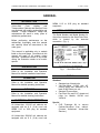
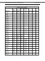
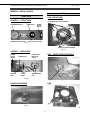
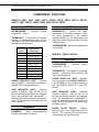
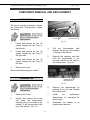
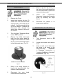
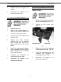
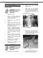
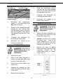
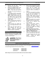
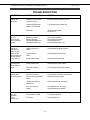
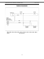
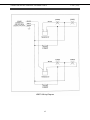
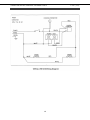
SERVICE MANUAL V SERIES FOOD HOLDING & TRANSPORTATION CABINETS AND BANQUET CARTS MODELS: VB90 VB96 VB150 VBP5I VBP7I VBP13I VBP15I VBP33 VBP77I VBS15 VHA9 VHA18 VHDP5 VHFA9 VHFA18 VHP3 VHP7 VHP8 VHP15 VHP20 ML-126548 ML-126550 ML-126552 ML-138030 ML-126358 ML-126359 ML-126360 ML-138075 ML-126361 ML-138033 ML-138072 ML-138073 ML-138035 ML-138070 ML-138071 ML-126343 ML-126344 ML-126345 ML-126346 ML-126347 This manual is prepared for the use of trained Vulcan Service Technicians and should not be used by those not properly qualified. This manual is not intended to be all encompassing. You should read, in its entirety, the repair procedure you wish to perform to determine if you have the necessary tools, instruments, and skills required to perform the procedure. Reproduction or other use of this Manual, without the express written consent of Vulcan, is prohibited. VULCAN-HART DIVISION OF ITW FOOD EQUIPMENT GROUP, LLC WWW.VULCANHART.COM Vulcan © 2009 All Rights Reserved 3600 NORTH POINT BLDV. BALTIMORE, MD 21222 F-41141 (11-09) V SERIES FOOD HOLDING, TRANSPORT, AND BANQUET CARTS F-41141 (11-09) IMPORTANT FOR YOUR SAFETY THIS MANUAL HAS BEEN PREPARED FOR PERSONNEL QUALIFIED TO INSTALL ELECTRICAL EQUIPMENT, WHO SHOULD PERFORM THE INITIAL FIELD STARTUP AND ADJUSTMENTS OF THE EQUIPMENT COVERED BY THIS MANUAL. READ THIS MANUAL THOROUGHLY BEFORE OPERATING, INSTALLING OR PERFORMING MAINTENANCE ON THE EQUIPMENT. WARNING Failure to follow instructions in this manual can cause property damage, injury, or death. WARNING Always Perform the Lockout/Tagout procedure before removing any sheet metal panels or attempting to service this equipment. Failure to comply with this procedure can cause property damage, injury, or death. WARNING Improper installation, adjustment, alteration, service, or maintenance can cause property damage, injury, or death. WARNING Do NOT operate this equipment without properly placing and securing all covers and access panels. WARNING In the event of a power failure, do not attempt to operate this device. WARNING Electrical and grounding connections must comply with the applicable portions of the National Electric Code and/or all local electric codes. WARNING Appliances equipped with a flexible electric supply cord, are provided with a three-prong grounding plug. It is imperative that this plug be connected into a properly grounded threeprong receptacle. If the receptacle is not the proper grounding type, contact an electrician. Do NOT remove the grounding prong from the plug. 1 V SERIES FOOD HOLDING, TRANSPORT, AND BANQUET CARTS F-41141 (11-09) TABLE OF CONTENTS IMPORTANT FOR YOUR SAFETY . . . . . . . . . . . . . . . . . . . . . . . . . . . . . . . . . . . . . . . . 1 GENERAL . . . . . . . . . . . . . . . . . . . . . . . . . . . . . . . . . . . . . . . . . . . . . . . . . . . . . . . . . . . 3 INTRODUCTION . . . . . . . . . . . . . . . . . . . . . . . . . . . . . . . . . . . . . . . . . . . . . . . . . 3 INSTALLATION . . . . . . . . . . . . . . . . . . . . . . . . . . . . . . . . . . . . . . . . . . . . . . . . . . 3 OPERATION . . . . . . . . . . . . . . . . . . . . . . . . . . . . . . . . . . . . . . . . . . . . . . . . . . . . 3 CLEANING . . . . . . . . . . . . . . . . . . . . . . . . . . . . . . . . . . . . . . . . . . . . . . . . . . . . . . 3 ELECTRICAL REQUIREMENTS . . . . . . . . . . . . . . . . . . . . . . . . . . . . . . . . . . . . . 3 SERIAL NUMBER LOCATION . . . . . . . . . . . . . . . . . . . . . . . . . . . . . . . . . . . . . . 3 TOOLS REQUIRED . . . . . . . . . . . . . . . . . . . . . . . . . . . . . . . . . . . . . . . . . . . . . . . 3 SPECIFICATIONS . . . . . . . . . . . . . . . . . . . . . . . . . . . . . . . . . . . . . . . . . . . . . . . . . . . . . 4 COMPONENT LOCATION . . . . . . . . . . . . . . . . . . . . . . . . . . . . . . . . . . . . . . . . . . . . . . . 5 CONTROLS . . . . . . . . . . . . . . . . . . . . . . . . . . . . . . . . . . . . . . . . . . . . . . . . . . . . . 5 ELEMENTS . . . . . . . . . . . . . . . . . . . . . . . . . . . . . . . . . . . . . . . . . . . . . . . . . . . . . 5 PROBE . . . . . . . . . . . . . . . . . . . . . . . . . . . . . . . . . . . . . . . . . . . . . . . . . . . . . . . . 5 POWER CORD . . . . . . . . . . . . . . . . . . . . . . . . . . . . . . . . . . . . . . . . . . . . . . . . . . 5 CONTROLS (VHFA9, VHFA18) . . . . . . . . . . . . . . . . . . . . . . . . . . . . . . . . . . . . . 6 POWER CORD WRAP (VHFA9, VHFA18) . . . . . . . . . . . . . . . . . . . . . . . . . . . . . 6 FAN (VHFA9, VHFA18) . . . . . . . . . . . . . . . . . . . . . . . . . . . . . . . . . . . . . . . . . . . . 6 COMPONENT FUNCTION . . . . . . . . . . . . . . . . . . . . . . . . . . . . . . . . . . . . . . . . . . . . . . . 7 CONTROLS . . . . . . . . . . . . . . . . . . . . . . . . . . . . . . . . . . . . . . . . . . . . . . . . . . . . . 7 ELEMENTS . . . . . . . . . . . . . . . . . . . . . . . . . . . . . . . . . . . . . . . . . . . . . . . . . . . . . 7 PROBE . . . . . . . . . . . . . . . . . . . . . . . . . . . . . . . . . . . . . . . . . . . . . . . . . . . . . . . . 7 CONTROLS (VHFA9, VHFA18) . . . . . . . . . . . . . . . . . . . . . . . . . . . . . . . . . . . . . 7 FAN . . . . . . . . . . . . . . . . . . . . . . . . . . . . . . . . . . . . . . . . . . . . . . . . . . . . . . . . . . . 8 ELEMENTS (VHFA9, VHFA18) . . . . . . . . . . . . . . . . . . . . . . . . . . . . . . . . . . . . . . 8 PROBE . . . . . . . . . . . . . . . . . . . . . . . . . . . . . . . . . . . . . . . . . . . . . . . . . . . . . . . . 8 LOCKOUT / TAGOUT PROCEDURE . . . . . . . . . . . . . . . . . . . . . . . . . . . . . . . . . . . . . . 8 COMPONENT REMOVAL AND REPLACEMENT . . . . . . . . . . . . . . . . . . . . . . . . . . . . 9 COVER REMOVAL . . . . . . . . . . . . . . . . . . . . . . . . . . . . . . . . . . . . . . . . . . . . . . . 9 THERMOMETER . . . . . . . . . . . . . . . . . . . . . . . . . . . . . . . . . . . . . . . . . . . . . . . . . 9 THERMOSTAT . . . . . . . . . . . . . . . . . . . . . . . . . . . . . . . . . . . . . . . . . . . . . . . . . 10 THERMOSTAT CALIBRATION . . . . . . . . . . . . . . . . . . . . . . . . . . . . . . . . . . . . . 10 DUAL LIGHT INDICATOR . . . . . . . . . . . . . . . . . . . . . . . . . . . . . . . . . . . . . . . . . 11 FAN . . . . . . . . . . . . . . . . . . . . . . . . . . . . . . . . . . . . . . . . . . . . . . . . . . . . . . . . . . 11 ON / OFF SWITCH . . . . . . . . . . . . . . . . . . . . . . . . . . . . . . . . . . . . . . . . . . . . . . 12 ELEMENT . . . . . . . . . . . . . . . . . . . . . . . . . . . . . . . . . . . . . . . . . . . . . . . . . . . . . 12 POWER CORD . . . . . . . . . . . . . . . . . . . . . . . . . . . . . . . . . . . . . . . . . . . . . . . . . 13 DOOR AND HINGE . . . . . . . . . . . . . . . . . . . . . . . . . . . . . . . . . . . . . . . . . . . . . . 13 DOOR GASKET . . . . . . . . . . . . . . . . . . . . . . . . . . . . . . . . . . . . . . . . . . . . . . . . . 14 SERVICE & PARTS INFORMATION . . . . . . . . . . . . . . . . . . . . . . . . . . . . . . . . . . . . . . 14 TROUBLE SHOOTING . . . . . . . . . . . . . . . . . . . . . . . . . . . . . . . . . . . . . . . . . . . . . . . . 15 WIRE DIAGRAMS . . . . . . . . . . . . . . . . . . . . . . . . . . . . . . . . . . . . . . . . . . . . . . . . 16 – 19 2 V SERIES FOOD HOLDING, TRANSPORT, AND BANQUET CARTS F-41141 (11-09) GENERAL INTRODUCTION NEMA 6-15 or 6-20 plug as standard equipment. Vulcan-Hart Food Holding and Transportation Cabinets and Banquet Carts are produced with quality workmanship and material. Proper installation, usage and maintenance will result in many years of satisfactory performance. SERIAL NUMBER LOCATION The Serial Number and Model Number for the unit are located on the Serial Data Plate, which is located by the electrical connection. (Fig. 1) Before performing maintenance on the cabinet/cart, thoroughly read this manual and carefully follow all instructions in the order given. This manual is applicable only to models listed on the cover page. Procedures in this manual will apply to all models unless specified. Illustrations can be of any model unless the illustration needs to be modelspecific. INSTALLATION Fig. 1 - Serial Data Plate Refer to the Installation and Operation Manual for detailed installation instructions. TOOLS OPERATION Standard • Standard set of hand tools. • Volt-Ohm-Meter (VOM) with AC current tester with sensitivity of at least 20,000 Ohms per volt. • Standard Thermometer • Pop Rivet Gun and 3/16” closed end rivets for Models VHFA9 and VHFA18. Refer to the Installation and Operation Manual for detailed operating instructions. CLEANING Refer to the Installation and Operation Manual for detailed cleaning instructions. ELECTRICAL REQUIREMENTS Special • CLR Treatment Kit to remove Calcium/Lime/Rust from cabinet. (Contact Authorized Vulcan-Hart Servicer.) All Vulcan-Hart 110/120 volt cabinets are equipped with an 8 ft. (2.4m) cord and NEMA 5-15 or 5-20 plug as standard equipment. All Vulcan-Hart 208/240 volt cabinets are equipped with an 8 ft. (2.4m) cord and 3 V SERIES FOOD HOLDING, TRANSPORT, AND BANQUET CARTS F-41141 (11-09) SPECIFICATIONS HEIGHT IN (mm) DEPTH IN (mm) WIDTH IN (mm) SHIPPING WT. Lb. (kg) VOLTS WATTS AMPS VB90 71.75" (1822) 42.75" (1086) 31.75" (806) 242# (110 kg) 120 2000 16.6 VB96 62" (1575) 29" (737) 51.5" (1308) 435# (197 kg) 120 2000 16.6 VB150 73" (1854) 29" (737) 61.25" (1556) 590# (268 kg) 120 2000 16.6 VBP5I 31.5" (800) 33.75" (857) 28.25" (718) 170# (77 kg) 120 1200 10 VBP7I 37.75" (959) 33.75" (857) 28.25" (718) 230# (104 kg) 120 1200 10 VBP13I 57.25" (1454) 33.75" (857) 28.25" (718) 340# (154 kg) 120 1200 10 VBP15I 67" (1702) 33.75" (857) 28.25" (718) 360# (163 kg) 120 1200 10 VBP33 43.5" (1105) 30.75" (782) 25.25" (643) 120 1200 10 VBP77I 72.5" (1842) 31.75" (806) 24.5" (622) 400# (182 kg) 120 2400 20 VBS7 37.625" (956) 30.25" (781) 23.75" (584) 195# (90 kg) 120 1200 10 VBS15 66" (1676) 30.25" (781) 23.75" (584) 315# (144 kg) 120 1200 10 VHA9 43.5" (1105) 30.75" (782) 25.25" (643) NA NA NA VHA18 71" (1804) 30.75" (782) 25.25" (643) NA NA NA VHDP5 62.25" (1582) 38" (966) 24.75" (629) 370# (169 kg) 120 2000 16.7 VHFA9 43.5" (1105) 30.75" (782) 25.25" (643) 190# (87 kg) 120 1200 10 VHFA18 71" (1804) 30.75" (782) 25.25" (643) 225# (102 kg) 120 2000 16.7 VHP3 23.5" (597) 23.75" (604) 18" (457) 80# (36.6 kg) 120 600 5 VHP7 28.5" (724) 25" (635) 18.25" (464) 80# (36.3 kg) 120 600 5 VHP8 31.5" (800) 25" (635) 18.25" (464) 90# (40.9 kg) 120 600 5 VHP15 61.25" (1556) 26.75" (680) 21.25" 540) 196# (89 kg) 120 1200 10 VHP20 61" (1549) 29" (737) 39.5" (1003) 264# (120 kg) 120 1200 10 MODEL NO. 4 V SERIES FOOD HOLDING, TRANSPORT, AND BANQUET CARTS F-41141 (11-09) COMPONENT LOCATION MODELS: VHP3, VHP7, VHP8, VHP15, VHP20, VBP5I, VBP7I, VBP13I, VBP15I, VBP77I, VBS7, VBS15, VHDP5, VB90, VB96, VB150, VBP33 CONTROLS CONTROL - FRONT VIEW THERMOMETER DIAL THERMOSTAT POWER INDICATOR LIGHT HEAT INDICATOR LIGHT Fig. 2 Fig. 4 CONTROL - INSIDE VIEWS POWER/HEAT INDICATOR LIGHTS THERMOSTAT PROBE THERMOMETER DIAL THERMOSTAT PROBE WIRE THERMOMETER Fig. 5 ELEMENT WIRE POWER WIRE POWER CORD Fig. 3 ELEMENTS Fig. 6 5 V SERIES FOOD HOLDING, TRANSPORT, AND BANQUET CARTS F-41141 (11-09) MODELS: VHFA9, VHFA18 FAN CONTROLS FAN - FRONT VIEW CONTROL - FRONT VIEW THERMOMETER DIAL (5) FAN MOUNTING PLATE SCREWS THERMOSTAT POWER INDICATOR LIGHT POWER ON/OFF SWITCH HEAT INDICATOR LIGHT Fig. 7 (4) FAN ATTACHING SCREWS Fig. 10 CONTROL - INSIDE VIEW POWER ON/OFF SWITCH ELEMENT WIRE THERMOSTAT PROBE WIRES FAN - INSIDE VIEW (HOUSING) POWER/HEAT INDICATOR LIGHTS THERMOMETER DIAL Fig. 8 Fig. 11 FAN POWER CORD WRAP Fig. 9 Fig.12 6 V SERIES FOOD HOLDING, TRANSPORT, AND BANQUET CARTS F-41141 (11-09) COMPONENT FUNCTION MODELS: VHP3, VHP7, VHP8, VHP15, VHP20, VBP5I, VBP7I, VBP13I, VBP15I, VBP77I, VBS7, VBS15, VHDP5, VB90, VB96, VB150, VBP33 CONTROLS THERMOMETER: temperature. (Fig. 2) Indicates PROBE interior THERMOSTAT: Controls the output temperature of the heating element. Once the output temperature of the heating element reaches the set temperature, the thermostat sensor removes power from the heating element. THERMOSTAT: Turns power on to heating element. Thermostat setting is from 1 to 10. The greater the thermostat setting number, the higher the temperature. Thermostat Setting 1 2 3 4 5 6 7 8 9 10 THERMOMETER: Senses the temperature in the cabinet. Approximate Temperature 100⁰F (37⁰C) 110⁰F (43⁰C) 120⁰F (49⁰C) 130⁰F (54⁰C) 140⁰F (60⁰C) 150⁰F (66⁰C) 160⁰F (71⁰C) 170⁰F (77⁰C) 180⁰F (82⁰C) 190⁰F (88⁰C) MODELS: VHFA9, VHFA18 CONTROLS THERMOMETER: temperature. (Fig. 7) Indicates interior THERMOSTAT: Turns power on to heating element. Thermostat setting number, the higher the temperature. POWER INDICATOR LIGHT: Indicates unit is plugged in and ON/OFF SWITCH is in the ON position. The red light will stay on until the ON/OFF Switch is in the OFF position. POWER INDICATOR LIGHT: Indicates unit is plugged in. As long as the cabinet is plugged in, the red light will stay on. HEAT INDICATOR LIGHT: Indicates element is heating. Light will stay on as long as the heating elements are engaged. Once the predetermined temperature is achieved, the heating elements will begin to cycle. During this period the amber light will turn on and off. HEAT INDICATOR LIGHT: Indicates element is heating. Light will stay on as long as the heating elements are engaged. Once the predetermined temperature is achieved, the heating elements will begin to cycle. During this period, the amber light will turn on and off. ELEMENTS POWER ON/OFF SWITCH: Supplies electrical power to the cabinet and turns on the fan. The cabinet will not have power unless switch is in the ON position. ELEMENTS: Heat element/elements located at the bottom of cabinet. 7 V SERIES FOOD HOLDING, TRANSPORT, AND BANQUET CARTS F-41141 (11-09) MODELS: VHFA9, VHFA18 (continued) PROBE FAN THERMOSTAT: Monitors/sensors the output temperature of the heating elements. Once the output temperature of the heating element reaches the set temperature, the thermostat sensor removes power from the heating element. The fan is located on top of the unit. The fan and air tunnel provide even heat distribution. The fan is turned on and off with the POWER ON/OFF SWITCH. THERMOMETER: Senses the temperature in the cabinet. ELEMENTS There are 2 heating elements located at the bottom of the cabinet. LOCKOUT / TAGOUT PROCEDURE Always perform the LOCKOUT / TAGOUT WARNING PROCEDURE before removing any sheet metal panels or attempting to service this equipment. FAILURE TO COMPLY WITH THIS PROCEDURE CAN CAUSE PROPERTY DAMAGE, INJURY OR DEATH. The Lockout / Tagout Procedure is used to protect personnel working on an electrical appliance. Before performing any type of maintenance or service on an electrically operated appliance, follow these steps: 1. In electrical box, place unit’s circuit breaker into OFF position. 2. Place a lock or other device on electrical box cover to prevent someone from placing circuit breaker ON. 3. Place a tag on electrical box cover to indicate that unit has been disconnected for service and power should not be restored until tag is removed by maintenance personnel. 4. Disconnect unit power cord from electrical outlet. 5. Place a tag on cord to indicate that oven has been disconnected for service and power should not be restored until tag is removed by maintenance personnel. 8 V SERIES FOOD HOLDING, TRANSPORT, AND BANQUET CARTS F-41141 (11-09) COMPONENT REMOVAL AND REPLACEMENT COVER REMOVAL The Cover must be removed to access the Thermostat, Thermometer, Lights, and Wiring. SCREWS ACCESS HOLE Fig. 13 1. 2. Locate and remove the two (2) screws holding the top cover to the left side. 4. Locate and remove the two (2) screws holding the top cover to the right side. Pull the thermometer bulb through the access hole located in the top of the cabinet. 5. Remove the retaining nuts that hold the thermometer to the housing located on the back of the control panel. (Fig. 14) 3. Locate and remove the two (2) screws holding the top cover to the back. 4. Remove the cover. (Reverse the above steps to install.) THERMOMETER THERMOMETER RETAINING NUTS Fig. 14 6. Remove the thermometer by pushing it from the rear through the control panel. 1. Remove the Cover. 7. 2. Identify and remove the screw that holds the thermometer sensing bulb on the inside of the cabinet. It will be mounted to the top of the cabinet. (Fig. 13) Install the replacement thermometer by reversing the above steps. 8. Reconnect the cabinet to its power source and test. 9 V SERIES FOOD HOLDING, TRANSPORT, AND BANQUET CARTS THERMOSTAT 1. Remove the Cover. 2. Identify and remove the two (2) screws that hold the thermostat sensing bulb on the inside of the cabinet. It will be mounted to the top of the cabinet. Push/pull the thermostat bulb through the access hole located in the top of the cabinet 3. Turn the black Thermostat Knob to the “OFF” position. 4. Remove the black thermostat knob from the control panel by using an allen wrench to loosen the two (2) set screws that hold it to the thermostat stem. (Fig. 15) F-41141 (11-09) 7. Remove the two (2) screws on the front of the control panel that hold the thermostat in place and remove the thermostat. 8. Install the replacement thermostat temperature sensing probe by reversing the steps above. 9. Reconnect the cabinet to its power source and test. THERMOSTAT CALIBRATION 1. Turn thermostat knob to Off position. 2. Loosen set screws and remove knob. 3. Using a small screw driver, turn the screw in the center of the thermostat stem: “clockwise to Decrease” temperature or “counter-clockwise to Increase” temperature. (Fig. 16) THERMOSTAT KNOB SET SCREWS Fig.15 5. Refer to the wiring diagram to identify the electrical leads that connect to the thermostat. 6. Disconnect the wire leads connected to the thermostat. Fig. 16 10 V SERIES FOOD HOLDING, TRANSPORT, AND BANQUET CARTS 5. Replace knob and tighten set screws. 6. Reconnect the cabinet to its power source and test. F-41141 (11-09) FAN VHFA9, VHFA18 DUAL LIGHT INDICATOR 1. Remove the cover. 2. Refer to the wiring diagram to identify the electrical leads that connect to the indicator light. 3. Disconnect the wire leads to the indicator light. 4. Depress the side mounted retaining clips on the indicator light housing and remove the light from the front of the control panel. 5. Complete the installation reversing the above steps. 7. Reconnect the cabinet to its power source and test. Remove the five (5) screws from the fan mounting plate. (Fig. 10) 2. Unplug the (Fig. 17) FAN POWER CORD fan power cord. CONNECTOR Fig. 17 Install the replacement indicator light by pushing it into the control panel opening and the retaining clips snap into place. 6. 1. 3. Remove the four (4) fan attaching screws and remove fan. (Fig. 10) 4. Install the replacement fan and complete the installation by reversing the above steps. 5. Reconnect the cabinet to its power source and test. by 11 V SERIES FOOD HOLDING, TRANSPORT, AND BANQUET CARTS ON / OFF SWITCH VHFA9, VHFA18 F-41141 (11-09) 2. Remove the bottom mounted element cover. 3. Remove the two (2) retaining screws that hold each element to the mounting plate and the one (1) screw for the element clip. (Fig. 18) MOUNTING PLATE RETAINING SCREWS 1. Remove the cover. 2. Refer to the wiring diagram to identify the electrical leads that connect to the switch. 3. Disconnect the wire leads to the switch. 4. Depress the top/bottom mounted retaining clips on the switch housing and remove it from the front of the control panel. NOTE: To expedite removal – cutting the retaining clips off with a knife or snips will make removal of the switch easier. (The switch will not be reusable if this is done.) 5. Install the replacement switch by pushing it into the control panel opening and the retaining clips snap into place. 6. Complete the installation reversing the above steps. 7. Reconnect the cabinet to its power source and test. ELEMENT CLIP SCREWS 4. Fig. 18 Gently pull the element away from the inner liner of the cabinet until the electrical lead wires are exposed. (Fig. 19 & 20) by ELEMENT Fig. 19 1. 5. Open the door to the cabinet. 12 Disconnect the element wires at the electrical lead connectors. V SERIES FOOD HOLDING, TRANSPORT, AND BANQUET CARTS LEAD WIRES LEAD CONNECTORS ELEMENT WIRES 6. 7. 8. 9. Fig. 20 F-41141 (11-09) 6. Install the replacement cord by inserting the cord and threaded portion of the strain relief through the opening in the cover. 7. Complete the installation reversing the above steps. 8. Reconnect the cabinet to its power source and test. Reconnect the replacement element to the lead wires with New wire connectors. DOOR INSTALLATION Gently tuck the residual wire back through the wire housing hole until the backing plate is lined up with the mounting holes, and is flush against the inner liner of the cabinet. Complete the installation reversing the above steps. 1. by POWER CORD 2. Remove the cover. 2. Refer to the wiring diagram to identify the electrical leads that connect to the power cord. 3. Disconnect the wire leads to the power cord. 4. Unscrew the retaining nut that holds the power cord strain relief to the cover. 5. Remove the power cord. Using a flat head screwdriver, pry the hinge cover away from the hinge until it snaps out. Caution: Use care not to scratch the hinge cover. Look for the small indentation on the inner portion of the hinge cover, as the location to pry the cover. Reconnect the cabinet to its power source and test. 1. by Remove the three (3) phillips head screws that attach the hinge to the door. Remove six (6) phillips head screws to replace hinge. (Fig. 21) Fig. 21 13 V SERIES FOOD HOLDING, TRANSPORT, AND BANQUET CARTS 3. 4. 5. 6. 7. 8. Remove the old door. You may need to open the latch. Remove the phillips head screws that attach the latch to the door. Note: There may be anywhere from two (2) to four (4) screws on the latch. If necessary, drill the new holes using a #19 drill bit (or 11/16” bit.) Note: When drilling holes into the cabinet frame, use a long drill bit (2”) as you need to drill through both sides of the 1” frame tubing. Apply a thread locker material to any screw/screws you are reinstalling. Using a screw gun, attach the door to the hinge and latch to the door. Close the door and check for gaps between the door and gasket. Adjust as necessary. Adjust the latch, if necessary. F-41141 (11-09) 1. 2. 3. 4. 5. DOOR GASKET 6. Before removing the old gasket, verify that the replacement gasket(s) are the correct size and length. Remove the old gasket by pulling it out of the aluminum J-channel. Verify that all gasket and adhesive has been completely removed before proceeding to step 3. Install the new gasket by starting at one end and pressing the gasket into the J-channel. A slotted screw driver may be needed to fully seat the gasket. You can also use “Pam Cooking Spray.” Note: Be careful not to puncture the gasket with the screw driver. Repeat until all gaskets have been replaced. Using a “food grade” sealant / adhesive, seal the corners to eliminate any gaps, and to prevent the gasket from sliding in the J-channel. Wipe away any excess sealant. Note: Allow 30 minutes for the sealant / adhesive to cure. When the sealant/adhesive has cured, close the door and check for gaps between the door and gasket. Adjust the gasket extusion, if necessary. SERVICE & PARTS INFORMATION To obtain Service and Parts information concerning this model, contact Vulcan-Hart Service Department at the address listed on the front cover of this manual or refer to our website: www.vulcanhart.com for a complete listing of Authorized Service and Parts depots. Customer Service Technical Service Service Parts 1-800-814-2028 1-800-814-2028 1-800-814-2028 When calling for service, have the model number and serial number available 14 V SERIES FOOD HOLDING, TRANSPORT, AND BANQUET CARTS F-41141 (11-09) TROUBLESHOOTING SYMPTOMS POSSIBLE CAUSES REMEDY Cabinet not operating. Cabinet not connected to power source. Connect cabinet to power source. Cabinet lighted power switch not turned ON. Turn lighted power switch ON. No power. Check circuit breaker. Check GFCI. GFCI or Ground Fault Circuit Indicator tripped Moisture problem. Shorted element. Pinched/damaged wire. Damaged power cord. Dry moisture problem. Check/replace element. Check/replace wire. Check/replace power cord. Cabinet is connected to power source, switch is ON, circuit breaker is ON but cabinet is not heating. Heating element is faulty. Check/replace heating element. Thermometer is faulty. Check/replace thermometer. . Thermostat is faulty. Check/replace thermostat. Power switch faulty. Check/replace power switch. Dual light indicator faulty. Check/replace Dual Light Indicator. Defective: element, thermometer, thermostat, switch. Check/replace: element, thermometer, thermostat, power switch. Thermostat requires adjustment. Perform thermostat calibration. Door not properly sealed. Check/adjust door and hinge. Check/replace door gasket. Fan not operating. Power switch not ON. Turn power switch on. (VHFA9, VHFA18 only) Fan faulty. Check/replace fan. Lighted power switch ON but not lit. Cabinet does not heat properly. 15 V SERIES FOOD HOLDING, TRANSPORT, AND BANQUET CARTS WIRING DIAGRAMS 16 F-41141 (11-09) V SERIES FOOD HOLDING, TRANSPORT, AND BANQUET CARTS 17 F-41141 (11-09) V SERIES FOOD HOLDING, TRANSPORT, AND BANQUET CARTS 18 F-41141 (11-09) V SERIES FOOD HOLDING, TRANSPORT, AND BANQUET CARTS 19 F-41141 (11-09)