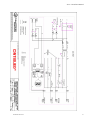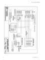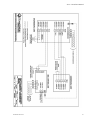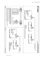
1
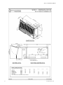
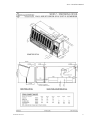
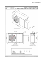
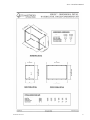
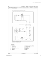
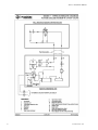
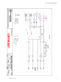
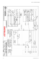
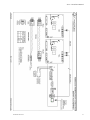
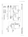
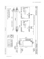
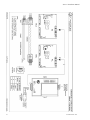
MISSION CRITICAL Air Conditioning Systems
Series 7, Wall Mount Units
Installation Manual
ClimateWorx International Inc.
S7-IM2014.DOC 2014
14 Chelsea Lane, Brampton, Ontario, Canada, L6T 3Y4
Series 7 Installation Manual
2
S7-IM2014.DOC 2014
Series 7 Installation Manual
Table of Contents
Table of Contents ................................................................................................................. 3
Site Preparation.................................................................................................................... 4
Location Consideration ....................................................................................................... 4
Positioning of Indoor units ................................................................................................ 4
Positioning of Condensing Unit ......................................................................................... 4
Positioning of Remote Controller Unit or Thermostat ....................................................... 5
Electrical Installation ........................................................................................................... 5
Power Feeding ................................................................................................................... 5
Interconnecting Wiring M52 only ...................................................................................... 5
Pipe Installation.................................................................................................................... 5
Recommended Pipe Size for Remote Condenser ................................................................ 6
Evacuation ......................................................................................................................... 6
Head Pressure Control System ........................................................................................... 7
Normal Charging ................................................................................................................. 9
Operating the Thermostat ................................................................................................... 9
Dimensional Details............................................................................................................ 14
Appendix A: Dimensional Drawings ................................................................................ 15
Appendix B: Piping Schematic Drawings ........................................................................ 20
Appendix C: Electrical Schematic Drawings................................................................... 24
S7-IM2014.DOC 2014
3
Series 7 Installation Manual
Site Preparation
In order to maximize operating efficiency and performance, the following areas should be observed at the
site-planning stage:
-
The room should be surrounded with a vapor seal to eliminate moisture migration through the
building structure. Windows should be sealed and at least double-glazed to prevent sweating. All
door jams should fit tightly and should not have any grilles in them. Polyethylene film type ceiling,
vinyl wallpaper or plastic based paint on the walls and slabs are recommended to minimize
absorption and transmission of moisture into the room.
-
Owing to a generally small population, a typical room should have fresh air kept at only about 5% of
the re-circulated air. This provides enough ventilation for personnel and pressurizes the room to
prevent dust from entering through leaks. The incoming fresh air must be filtered very closely, and
preferably pretreated. Otherwise heating, cooling, humidifying and dehumidifying loads of the
incoming fresh air should be taken into account in determining total loading requirements.
Location Consideration
Positioning of Indoor units
The Series 7 unit is designed for mounting on a vertical wall. Care should be taken to ensure that the
supply and return air-paths are not blocked by equipment.
The room layout should provide 508mm (20”) service clearance in the front of the unit for the routine
service and maintenance.
Positioning of Condensing Unit
The condensing unit should be located as close to the indoor unit as possible. From a security and
environment standpoint, the condensing units should be installed away from public access and occupied
spaces where low ambient sound level is required.
In order to avoid short circuit and inter unit re-circulation, condensing units should be located at least 1m
(3.3 ft.) away from any walls, obstructions or adjacent units. To ensure maintenance-free operation,
condensing units should be located away from the areas that are continuously exposed to loose dirt and
foreign materials that may clog the coil.
The condensing units should be firmly secured on steel supports or concrete plinths.
4
S7-IM2014.DOC 2014
Series 7 Installation Manual
Positioning of Remote Controller Unit or Thermostat
The remote mounted controller or thermostat should be located in an easily accessible area within reach
of operating personnel. Consideration should be given to interconnecting wiring between indoor unit and
controller. (Cables supplied pre-made from factory when unit is ordered with M52 controller). The
maximum distance between indoor unit and controller should be 15 ft. (4.5 M)
Electrical Installation
Power Feeding
All models are fitted with a 3-terminal connection block, for live, neutral and earth connections, which
are located at the lower right corner of the power panel.
The power cables should be sized in accordance with local and national codes. Refer to the unit nameplate
for circuit ampacity, and wiring diagrams packed with each unit.
Interconnecting Wiring M52 only
Pre-made control cable sets are supplied with each unit for connecting both the outdoor unit and remote
mounted controller to the indoor unit. All connectors are terminated with standard crimp connectors. Each
cable will be clearly marked and care should be taken to ensure cables are connected correctly. See drawing
No. S7ED500A – Interconnecting Wiring
Pipe Installation
Condensate Drain
For proper drainage a P-trap MUST be installed. Total height for the trap should be measured from the
bottom of the drain pan (4” above unit bottom), to the bottom of the “U” in the trap. Minimum recommended
height is 3.5” to ensure proper drainage.
Refrigerant Piping
Good practice should always be followed when connecting refrigerant piping in direct expansion systems.
As many of the operational problems encountered in a refrigeration system can be traced back to
improper design and installation of refrigerant piping, it is essential that the following guidelines be
observed:
S7-IM2014.DOC 2014
5
Series 7 Installation Manual
-
Use clean and dehydrated refrigeration quality tubing with both ends sealed.
-
Cut and form tubes carefully to avoid getting dirt or metal particles into the refrigeration lines. Never
use a hacksaw to cut the tubing.
-
Once the system is open, complete the work as quickly as possible to minimize ingress of moisture
and dirt into the system. Always put caps on ends of tubes and parts not being worked on.
-
To prevent scaling and oxidation inside the tubing, pass an inert gas such as nitrogen through the line
while carrying out brazing, silver soldering or any other welding processes.
-
It is recommended that quality refrigeration solder (95% tin, 5% silver) is used for its excellent
capillary action.
-
Use minimum amount of solder flux to prevent internal contamination of the piping. Use flux with
care as it is usually acidic in nature.
-
Install a trap on the bottom of a vertical riser of the suction line and one every 6m (20ft.) in elevation
to collect refrigerant and lubrication oil during off cycle.
-
Insulate the suction line. Insulate liquid lines that may be subjected to high heat gains.
-
Design and arrange refrigerant piping for the evaporator in such a way that it minimizes pressure
drop to 3 psig and allows adequate velocity of refrigerant to prevent oil trapping. Recommended pipe
sizes are tabulated as follows:
Recommended Pipe Size for Remote Condenser
Models
Liquid Line
25 ft. equivalent pipe length
50 ft. equivalent pipe length
7A1.5
7A2.0
7A2.5
3/8”
3/8”
3/8”
3/8”
3/8”
3/8”
5/8”
5/8”
5/8”
3/4”
5/8”
3/4”
Suction Line
25 ft. equivalent pipe length
50 ft. equivalent pipe length
Consult Factory for additional distances
Evacuation
The procedure for leak testing and evacuation of the system is as follows:
6
S7-IM2014.DOC 2014
Series 7 Installation Manual
1.
Connect a gauge manifold to the compressor suction and liquid service valves.
2.
Open all service valves.
3.
Charge the system with dry nitrogen to approximately 150 psig.
4.
Leave pressure in system for at least 12 hours. If pressure holds, continue with next step. If the
pressure drops detect and seal leak before continuing.
5.
Release all pressure.
6.
Connect a vacuum pump to the suction and liquid service valves with refrigerant or high vacuum
hoses. Provide an isolating valve and a pressure gauge for pressure checking.
7.
Evacuate the system to an absolute pressure not exceeding 1500 microns. Break the vacuum to 2psig
with dry nitrogen. Repeat the evacuation process and then re-break the vacuum with dry nitrogen.
8.
Open the liquid and suction ports. Evacuate to an absolute pressure not exceeding 500 microns. Let
the vacuum pump run without interruption for minimum two hours.
9.
Stop the vacuum pump. Let the system remain in vacuum for 30 minutes. If the vacuum holds, break
the vacuum and weigh in the system charge with vapor R22/R407C (see nameplate for operating gas)
through the suction side of the compressor. If the vacuum doesn’t hold, repeat leak test and continue
from the top.
10. Allow the pressure to equalize.
Head Pressure Control System
For condenser or condensing units, possibly subjected to extremely low ambient temperatures, it is
recommended that a head pressure control system be installed to avoid starving the evaporator coil
resulting in oil logging; short cycling by low pressure control; reduction of the system capacity and erratic
expansion valve operation.
A drop in the condensing pressure often occurs in air-cooled systems as a result of low ambient
conditions encountered during fall-winter-spring operation. Head pressure control renders part of the
condenser surface inactive. The reduction of active condensing surface results in a rise in condensing
pressure and hence provides a sufficient liquid line pressure for normal system operation. The head
pressure control system allows operation at extremely low ambient temperature down to -40°F.
S7-IM2014.DOC 2014
7
Series 7 Installation Manual
ClimateWorx uses a single valve head pressure control, with a heated receiver for factory ordered
condensers. The OROA is located in the liquid drain line between the condenser and the receiver, and has
a bypass line from the hot gas line.
During periods of low ambient temperature, the condensing pressure falls until it approaches the setting of
the OROA valve. The valve (non-adjustable) then throttles, restricting the flow of liquid from the
condenser. This causes refrigerant to back up in the condenser thus reducing the active condenser surface.
This raises the condensing pressure. Since it is really the receiver pressure that needs to be maintained,
the bypass line is required to heat up the cold liquid being passed by the OROA. Thus the liquid reaches
the receiver warm and with sufficient pressure to assure proper expansion valve operation. As long as
sufficient refrigerant charge is in the system, the valve modulates the flow automatically to maintain
proper receiver pressure regardless of outside ambient.
Charging
When head pressure control is utilized, there must be enough refrigerant to flood the condenser at the
lowest expected ambient and still have enough charge in the system for proper operation. After
completing the evacuation procedures follow these guidelines for charging:
1.
Close the main power and allow the compressor crankcase heater to operate for at least one hour.
2.
Connect the gauge manifold to both suction and liquid service valves, with the common connection
to the refrigerant drum. Purge the lines and open the refrigerant drum vapor valve.
3.
Start the compressor using the test mode to energize the main fan and compressor.
4.
Open the suction connection on the gauge manifold. Modulate the rate of charging with the gauge
manifold valve. Watch the discharge pressure closely during the charging operation to ensure that the
system is not overcharged. It is a good practice to weigh the amount of gas added.
5.
Charge the system until the sight glass is clear of bubbles. The system is now correctly charged for
operating under head pressure control at the ambient temperature charging is being carried out.
6.
If the system is designed to operate at ambient below the ambient that exists during the charging, additional
charge will have to be added now.
7.
Read from the following table the percentage of condenser to be flooded at charging and that at expected
minimum ambient temperature, then calculate the difference:
Ambient Temperature in °F
70
65
60
55
50
45
40
35
8
Percentage of Condenser to be Flooded
0
0
10
24
33
41
46
52
S7-IM2014.DOC 2014
Series 7 Installation Manual
30
25
20
10
0
-10
-20
-30
-40
55
59
62
66
70
73
76
77
79
8.
The flooded condenser capacity on all Series 7 condensing units is 4.4 lbs.
9.
Multiply the value found in Step 8 by the difference in percentages calculated in Step 7; this gives the
additional charge needed.
10. Fill in the required charge to the receiver.
Normal Charging
Proper performance of the system depends largely on proper charging. Adhere to the following guidelines
for charging:
1.
Close the main isolator and allow the compressor crankcase heater to operate for at least one hour.
2.
Connect the gauge manifold to both liquid and suction service valves, with a common connection
to the refrigerant cylinder. Purge the lines and open the refrigerant cylinder vapor valve.
3.
Start the compressor using the test mode to energize the main fan and compressor valve.
4.
Open the suction connection on the gauge manifold. Modulate the rate of charging with the gauge
manifold valve. Watch the discharge pressure closely during the charging operation to ensure that
the system is not overcharged.
5.
Charge the system until the sight glass is just clear of bubbles.
6.
Compare the temperature of the liquid line leaving the condenser with the saturation temperature
equivalent to the condensing temperature. Continue charging until the liquid line temperature is
approximately 5°F below the condensing temperature.
Operating the Thermostat
S7-IM2014.DOC 2014
9
Series 7 Installation Manual
Setting the Current Day and Time
1.
Press the CLOCK Button. The display will flash a day of the week.
2.
Press the up or down arrow buttons until the current day shows.
3.
Press the CLOCK button again. The display will flash the hour. (Note the AM/ PM indicator.)
4.
Press the up or down arrow buttons until the current hour shows.
5.
Press the CLOCK button again. The display will flash the minutes.
6.
Press the up or down arrow buttons until the current minutes show.
7.
Press the CLOCK button and the current day and time are now set.
* Note: If a button is not pushed in 15 seconds, the thermostat will automatically return to normal
operation.
Setting your Program Temperatures
With your specific program determined, you are ready to begin programming. You will now enter the
individual program period temperatures for the heating program.
1.
Press the MODE button until HEAT is displayed.
2.
Press the SET TEMP button. The first program period (Morning) will be displayed.
3.
Press the up or down arrow buttons to adjust that program period’s temperature for heating.
4.
Repeat Steps 2 and 3 for the Day, Evening and Night program periods. Remember, if your
thermostat was set for two program periods, you will only have to repeat Steps 2 and 3 for the Night
program period.
5.
Press the MODE button until COOL is displayed. You now will enter the individual program period
temperatures for the cooling program.
6.
Repeat Steps 2, 3 and 4 for the cooling temperatures.
7.
Press the MODE button until your desired mode of operation appears: HEAT- AUTO- OFF- COOL.
8.
Press the RESUME button to return to normal operation.
Note: If a button is not pushed in 15 seconds, the thermostat will automatically return to normal
operation. You may go back into the programming portion simply by repeatedly pressing the SET TEMP
button until you get back to where you left off.
Setting your Program Times
Referring to your Schedule Planner, you now will enter the times for the program periods.
10
S7-IM2014.DOC 2014
Series 7 Installation Manual
1.
Press the PROGRAM button. The display will flash a day of the week.
2.
Press the up or down arrow buttons to select the day you wish to program. (We suggest starting with
Monday.)
3.
Press the PROGRAM button. The display will flash the hour of the first period (Morning). (Note the
AM/ PM indicator.)
4.
Press the up or down arrow buttons to adjust the desired hour for the first program period.
5.
Press the PROGRAM button again. The display will flash the minutes.
6.
Press the up or down arrow buttons to adjust the desired minutes for the first period. (Note the
minutes are in increments of 10.)
7.
Repeat Steps 3- 6 for the Day, Evening and Night periods. Remember that if your thermostat was set
for two program periods, you will only have to repeat Steps 3- 6 for the Night period.
8.
After entering the Night period, press the PROGRAM button. COPY will be displayed. The copy
function will allow program times to be copied to sequential days. If you do not wish to copy the
program times to another day (or block of days), proceed to Step 11.
9.
Press the up or down arrow buttons to select the next individual day, or block of days, to copy the
program times to.
10. Press the PROGRAM button to copy the program times to the selected days of the week.
11. Repeat Steps 1- 10 for any remaining unprogrammed days of the week.
12. When finished, you can verify that all program periods are programmed correctly by repeatedly
pressing the PROGRAM button. When COPY appears, press the PROGRAM button to skip to the
next day.
* Note: If a button is not pushed in 15 seconds, the thermostat will automatically return to normal
operation. You may go back into the programming portion simply by repeatedly pressing the
PROGRAM button until you get back to where you left off.
Temperature Override
Temporary Override (3 hours)
You may change the temperature setting temporarily at any time without affecting the program.
Press the up or down arrow buttons. The current event temperature and mode of operation will be
displayed. Press the up or down arrow buttons again to adjust the temperature. This temperature will be
maintained for three hours. To cancel, simply press the RESUME button.
Temporary Override with Keyboard Locked (1 hour) (300- 225, 300- 227, 300- 229)
S7-IM2014.DOC 2014
11
Series 7 Installation Manual
You may change the temperature setting temporarily at any time without affecting the program, even
though the keypad is locked.
• Press the up or down buttons. The display will show the temperature for the first event. Press the up or
down buttons again to adjust the temperature +/- 3 degrees. This temperature will be maintained for one
hour.
Continuous Override (Hold)
You also may maintain a constant temperature setting at any time without affecting the program.
1.
Press and release the MODE button until the desired mode is displayed (HEAT – AUTO – OFF –
COOL)
2.
Press and release the HOLD button. HOLD will be displayed.
3.
Press the up or down buttons to adjust the temperature. This temperature will be maintained
indefinitely. To cancel, simply press the RESUME button.
Note: If the auto mode is used, press the MODE button, then press the up or down buttons to select a
heating setpoint. Press the MODE button, and then press the up or down buttons to select a cooling
setpoint.
Changing Fahrenheit (°F) to Celsius (°C)
This thermostat is preset to display the temperature in Fahrenheit. You may change the display to Celsius. To change
from one to the other, simultaneously press the up and down buttons. The display will change automatically.
Changing 12 Hour Time to 24 Hour Time
This thermostat is preset to display the standard 12 hour time format. You may change the display to the 24 hour time
format. To change from one to the other, press and release the CLOCK button, then press the MODE button. The
display will change automatically.
12
S7-IM2014.DOC 2014
Series 7 Installation Manual
Power Failures
This Robertshaw thermostat will maintain the program settings during any type of power failure. If power
fails, AC will be displayed for 30 minutes. After 30 minutes, the display will go blank. If power is
restored within the first 30 minutes, the thermostat will resume normal operation. If power is restored
after 30 minutes, 12: 00 AM will flash, and the thermostat will control to the night event setpoint until the
clock is reset. Once the clock is reset, the thermostat will resume normal operation.
S7-IM2014.DOC 2014
13
Series 7 Installation Manual
Dimensional Details
The following tables summarize the dimensional detail drawing number for Series 7 units with standard
options.
For units with a special option or configuration, please consult factory for details.
14
Model
Indoor Unit
-15
S7DD101
-20
S7DD101
-25
S7DD101
Outdoor Unit
S7DD302
S7DD302
S7DD302
S7-IM2014.DOC 2014
Series 7 Installation Manual
Appendix A: Dimensional Drawings
SERIES 7 – Wall Mount Indoor Unit
S7DD101
13
SERIES 7 - Humidifier Unit w/ Evap Unit Dimensional Detail
S7DD102
14
SERIES 7 – Outdoor Air-cooled Condensing Unit Dim. Detail
S7DD302
15
SERIES 7 – Water-cooled Condensing Unit Dim. Detail
S7DD401
16
S7-IM2014.DOC 2014
15
Series 7 Installation Manual
16
S7-IM2014.DOC 2014
Series 7 Installation Manual
S7-IM2014.DOC 2014
17
Series 7 Installation Manual
18
S7-IM2014.DOC 2014
Series 7 Installation Manual
S7-IM2014.DOC 2014
19
Series 7 Installation Manual
Appendix B: Piping Schematic Drawings
20
Drawing Title
Drawing No.
SERIES 7 – Air-Cooled System Schematic
S7DS102
Page No.
18
SERIES 7 – Water-Cooled System Schematic
S7DS201
19
SERIES 7 – Glycol-Cooled System Schematic
S7DS301
20
SERIES 7 – Chilled Water System Schematic
S7DS401
21
S7-IM2014.DOC 2014
Series 7 Installation Manual
S7-IM2014.DOC 2014
21
Series 7 Installation Manual
22
S7-IM2014.DOC 2014
Series 7 Installation Manual
S7-IM2014.DOC 2014
23
Series 7 Installation Manual
Appendix C: Electrical Schematic Drawings
Drawing Title
Drawing No.
Page No.
SERIES 7 – Interconnecting Wiring Thermostat Control, Chilled WaterS7ES603
24
SERIES 7 – Interconnecting Wiring Thermostat Control, Direct Exp.
25
S7ES609
SERIES 7 - Interconnecting Wiring Thermostat Control, Chilled Water S7ES611
With Optional Modulating Valve
24
26
SERIES 7 - Interconnecting Wiring M52 Controller, Direct Exp.
With Optional Humidifier
S7ES500
27
SERIES 7 - Interconnecting Wiring M52 Controller, Direct Exp.
Without Optional Humidifier
S7ES501
28
SERIES 7 – Interconnecting Wiring M52 Controller, Chilled Water
S7ES502
29
SERIES 7 - Electric Schematic – Co-Work I2C Interconnection Link
M52ES13
30
SERIES 7 – Electric Schematic – Field Wiring Standby Start/
Standby Enable, For automatic change over
M52ES05
31
SERIES 7 - Electric Schematic – Embedded Web Browser Connection, M52ES20
Serial to Ethernet Communication Link
32
SERIES 7 - Electric Schematic – Embedded Connection,
Serial to Ethernet Communication Link
M52ES25
33
SERIES 7 - Electric Schematic – Embedded Connection,
Serial to Ethernet (Lonworks) Communication Link
M52ES26
34
SERIES 7 - Electric Schematic – Embedded Connection,
Serial to Serial Communication Link
M52ES27
35
S7-IM2014.DOC 2014
Series 7 Installation Manual
S7-IM2014.DOC 2014
25
Series 7 Installation Manual
26
S7-IM2014.DOC 2014
Series 7 Installation Manual
S7-IM2014.DOC 2014
27
Series 7 Installation Manual
28
S7-IM2014.DOC 2014
Series 7 Installation Manual
S7-IM2014.DOC 2014
29
Series 7 Installation Manual
30
S7-IM2014.DOC 2014
Series 7 Installation Manual
S7-IM2014.DOC 2014
31
Series 7 Installation Manual
32
S7-IM2014.DOC 2014
Series 7 Installation Manual
S7-IM2014.DOC 2014
33
Series 7 Installation Manual
34
S7-IM2014.DOC 2014
Series 7 Installation Manual
S7-IM2014.DOC 2014
35
Series 7 Installation Manual
36
S7-IM2014.DOC 2014