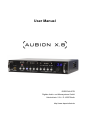
1
User Manual
DSPECIALISTS
Digitale Audio- und Messsysteme GmbH
Helmholtzstr. 2-9 L D-10587 Berlin
http://www.dspecialists.de
User Manual AUBION X.8
Table of contents
1
Introduction
1
2
Scope of delivery
2
3
System requirements
2
4
Installation and quickstart
2
5
Hardware
3
6
Configuring the X.8
5
6.1
Entering settings in the X.8 GUI
5
6.1.1 Device list
6
6.1.2 Connecting to an X.8
6
6.1.3 Line-Out settings
7
6.1.4 Mic/Line-In switchover
8
6.1.5 Mic settings
8
6.1.6 In 7/8 settings
9
6.1.7 Line-In settings
9
6.1.8 S/PDIF settings
10
6.1.9 Selecting the monitoring channel
10
6.1.10 Setting the audio cycle and the synchronization source
11
6.1.11 Loading and saving settings
11
6.1.12 Manually updating the X.8 software
12
6.1.13 Automatic recognition of outdated firmware
12
6.1.14 Advanced settings
13
6.1.15 Device information
14
6.1.16 GUI information
14
Settings on the X.8
15
6.2.1 Configuration of the input and output amplifications
15
6.2.2 Level displays
16
6.2.3 Line-Out mute
16
6.2.4 Status of the phantom power supply
16
6.2
7
General ASIO operation
17
8
Working in SysTune and EASERA
17
9
Technical reference
18
9.1
18
Technical data
User Manual AUBION X.8
9.2
Connections
19
9.2.1 Power supply
19
9.2.2 Network interfaces
20
9.2.3 Line-Outs
21
9.2.4 Mic-/Line-In 1 to 4
22
9.2.5 Line-In 1 to 8
24
9.2.6 S/PDIF input and output
25
9.2.7 Headphone socket
26
9.3
ASIO and X.8 channel assignment
26
9.4
Connection logic and status change
27
9.5
Configurations in X.8 GUI vs. X.8 device
27
9.6
Block diagram of X.8
28
10 Contact / Imprint
29
User Manual AUBION X.8
This page is intentionally left blank.
User Manual AUBION X.8
1 Introduction
Thank-you for choosing an AUBION X.8!
The X.8 is a professional multi-channel audio AD/DA converter with integrated microphone
amplifiers and real-time transport for eight Mic/Line/SPDIF input ports and four Line/SPDIF
output ports via a conventional Ethernet network (100 Mbit/s or 1 Gbit/s) from and to your
PC.
In combination with measuring software tools from AFMG (e.g. EASERA, SysTune) the X.8
is a measurement device for high-precision acoustic measurements. It therefore provides
you with a measurement solution on which you can carry out simultaneous measurements of
(room) impulse responses, frequency responses, echo times, STI, SPL, LEQ and NC in real
time on eight input ports.
The X.8 presents the audio channels on your PC in the form of a multi-client ASIO device
driver. In addition, the X.8 installation software installs a graphic user interface (X.8 GUI) on
your PC which does not require further configuration as well as an X.8 service (Windows
service) that exchanges all control information with the X.8 in the background. This means
that the X.8 can be used by all ASIO-capable audio applications on the market.
In summary, the AUBION X.8 has the following features:
·
Two fast Gigabit network interfaces (1000BaseT) with integrated network switches
provide for extremely simple cabling even across distances of up to 100 metres with
standard CAT5e cables for your measurement device, measurement PC and
network.
·
The integrated Zeroconf technology configures the IP network settings automatically.
In connection with the X.8 drivers, which are included in the package, you can
concentrate immediately on your measurement work without having to be a network
expert – a real plug-and-play system!
·
The included AUBION X.8 Multiclient ASIO driver allows you to use any, as well as
several, active PC measurement applications which you need for the simultaneous
real-time analysis of the eight AUBION X.8 input ports and the four output ports.
·
Synchronous sampling of the analog signals on all input connectors with premium
192 kHz/24 bit A/D and D/A converters and simultaneous presentation of the audio
data on your PC’s time line in your measurement application.
·
Sampling rates of 44.1 kHz, 48 kHz, 88.2 kHz and 96 kHz can be set. Primed for the
higher sampling rates 176.4 kHz and 192 kHz.
·
Four high-quality microphone preamplifiers with accurate dB amplification of up to
65 dB and excellent sound properties with down to 0.0003% THD+N.
+48V phantom power can be activated for connection to high-quality condenser
measurement microphones.
·
Primed for the audio synchronisation of several X.8 in a network for smooth scaling
of the audio channels.
·
Very robust and compact construction for mobile use. In addition to all audio
interfaces, the ½ 19“ / 1HE form factor of the casing contains a front panel that can
be operated intuitively and you can set all important measurement parameters
independent of your PC.
1/29
User Manual AUBION X.8
2 Scope of delivery
Your AUBION X.8 package includes the following components:
·
AUBION X.8 device
·
Mains adapter (power supply)
·
X.8 driver CD
3 System requirements
Minimum hardware requirements:
·
1.5 GHz processor speed or higher (multi-core processors are recommended)
·
1 GB RAM (2 GB or more recommended, especially for Vista and Windows 7)
·
900 x 500 display resolution (1024 x 768 or higher recommended display resolution)
·
100 Mbit/s or 1000 Mbit/s Ethernet port
Minimum software Requirements:
·
Windows XP (SP3), Windows Vista (SP2), Windows 7
·
Adobe Acrobat Reader 4.0 (or later)
4 Installation and quickstart
If you want to use the X.8 for the first time, you first of all have to install Bonjour, a PC
service provided by Apple to automatically recognize compatible devices, as well as the X.8
device driver with the control software on a compatible PC.
1. Download the software (Bonjour Print Services for Windows) from the following
website and install it: http://support.apple.com/kb/DL999
(Make sure that your firewall settings allow you to use the UDP port 5353.)
2. The X.8 device driver and control software (X.8 GUI) can be found on the CD
provided. Start the setup.exe file on the CD and follow the instructions that appear
on your screen. After the software has been successfully installed, the X.8 GUI
(Aubion.X8.exe) can be found in the \AUBION\X.8\bin folder in Program
Files. Start the software by clicking the desktop symbol or go to the Windows start
menu, to the AUBION\X.8 folder and click AUBION X.8.
3. Connect the network cable to one of the two X.8 network interfaces and connect the
device to the network in which the software installation is also located. Connect the
mains adapter provided to the X.8 and switch it on. Two lines (--) first of all appear on
the two-digit display and, after ten seconds, a numerical value is displayed. The
network activity LEDs on the back of the device should flash.
4. If everything has been correctly installed, the X.8 name appears in the main window
of the X.8 GUI in max. 60 seconds after you have switched on the X.8 device list
(Device:)
5. After selecting the X.8 in the list, you can configure it using the X.8 GUI. An ASIOcapable application (e.g. EASERA SysTune) can be started to carry out
measurements after the X.8 ASIO driver has been selected in this application (ASIO:
AUBION X.8).
2/29
User Manual AUBION X.8
5 Hardware
Front panel of the X.8:
·
Setting and display of the input and output gains, the phantom power supply and the
signal level.
·
Port for stereo monitoring headphones; electrically asymmetric
Rear side of the X.8:
·
·
Ethernet ports 1+2: a 10/100/1000BaseT each on two RJ45 sockets;
o
The two network ports can be seen as connections of a 2-port Ethernet
switch; this means, for example, that the X.8 can be connected between PC
and network.
o
The connections serve to transmit eight audio channels from the X.8 and four
audio channels to the X.8 and are also used for configuration, and firmware
updates via an Ethernet network.
Input channels 1 to 8:
o
4 symmetric Mic/Line inputs to 4 XLR/TRS combo sockets (in 1 to 4)
o
4 Line inputs (IN 1 to 4) as well as 4 more symmetrical Line inputs to DSUB25 socket (IN 1 to 8)
o
Alternatively to Line-In 7/8, you have the option of S/PDIF-In 7/8; S/PDIF-In
can be connected to an RCA/cinch socket; the status of the current setting for
In-7/8 is shown by an LED on the rear side (IN 7/8: off = Line-In / on = S/PDIFIn)
o
Mic/Line changeover switch (for In 1 to 4) in X.8-GUI
o
The gain regulator (for IN 1 to 8) can be controlled on the front panel of the
X.8 or in the GUI
§
For MIC IN: 0, +10, +11, ..., +65 dB
§
For LINE IN: 0, +9, +15, +18 dB
3/29
User Manual AUBION X.8
·
·
·
Output channels 1/2:
o
2 line outputs to 2 TRS jack plugs
o
Reference level for digital full scale level (0 dBFSpeak): +3 dBu, +6 dBu,
+12 dBu and +21 dBu can be adjusted in the X.8 GUI
o
The gain regulator (0..-100 dB) can be controlled on the front panel of the X.8
or in the GUI
Sampling rates and synchronization:
o
Synchronization either on internal master (44.1 kHz, 48 kHz, 88.2 kHz and
96 kHz can be set in the X.8 GUI) or on the S/PDIF-IN master clock1.
o
The synchronization status is shown by an LED on the rear side (EXT SYNC:
off = internal / on = S/PDIF-In).
Mains connection 17 to 27 VDC for the mains adapter provided: max. 20W
The technical data for the X.8 can be found in section 9.1.
An enlarged block diagram can be found in section 9.1.
1
The synchronisation source S/PDIF-In will be available in a future firmware version.
4/29
User Manual AUBION X.8
6 Configuring the X.8
An X.8 can be extensively configured on the device's front panel or on your PC. While the
X.8 GUI shows you all setting options and status displays, gain settings can be done on the
front panel and some of the operating states are displayed there.
Gain changes can be made at the same time on the front operating panel of the X.8 and in
the X.8 GUI. The gain settings are displayed simultaneously on both.
All settings, no matter whether you have activated them in the X.8 GUI or on the front
operating panel, are always saved on the X.8 device. As such, an X.8 always starts with the
last settings when you switch it on.
6.1 Entering settings in the X.8 GUI
The X.8 GUI is set up like a typical graphic user interface for controlling external sound
cards. It consists of the following elements:
·
Settings for input and output gains with slide controls for individual channels and the
corresponding level displays.
·
A number of individual configuration switches.
·
A menu with additional functions.
·
A status display along the bottom shows information on the GUI version and the X.8
service as well as on the hardware and firmware of any device connected.
On the left-hand side there is a drop-down list in which the X.8 devices available in the
network are shown. As soon as the X.8 GUI or the X.8 service working in the background is
connected to an X.8, the levels of the input and output channels as well as all device
configurations are displayed in real time.
The slide control, which can be used to set the input and output amplification on every
channel individually, is on the right-hand side. On the slide controls for the two analog output
channels, you can use the Mute button to mute both channels simultaneously.
Above each of the slide controls for the input channels, there are two switch elements - one
ON/OFF switch for the phantom power supply and one switch for configuring the respective
channel as a Line or Mic channel.
The SPDIF In 7/8 button is located above the last pair of channels. As soon as this is activated,
channels 7 and 8 instead of the last two Line-In channels are occupied by the two S/PDIF
input channels.
5/29
User Manual AUBION X.8
If the X.8 GUI is closed by clicking the [X] button in the corner of the window, the software
does not terminate, but is only minimized in the Windows system tray. Clicking the X.8
Systray symbol with the left-hand mouse button opens the software again. With the righthand mouse button, click Exit or File / Exit in the menu in the main window to terminate the
application.
6.1.1 Device list
After the X.8 GUI has started, the control software lists all
X.8 devices found in the network in the Device List
(Device:) . The devices are each displayed with the prefix
"AubionX8_" and the last three octets of their MAC
addresses as a suffix, for example, "00-00-48".
X.8 devices separated from or added to the network are updated in the Device List within
max. 60 seconds.
When this happens, the X.8 icon in the System Tray automatically gives you information
about the change in the connection statuses:
·
New X.8 in the network
·
Previously connected X.8 has returned to the network
·
Previously connected X.8 no longer in the network
·
X.8 has been transferred to another X.8 GUI
All status changes are shown in section 9.4.
6.1.2 Connecting to an X.8
You can select exactly one X.8 you have found in the Device List (see section 6.1.1)
manually so that the X.8 service running in the background connects immediately to this
device. As soon as the connection has been established, the X.8 GUI shows you all
currently set device parameters (input and output gains, source selection, etc.) and the signal
level in real time. In addition, further X.8 GUI devices and GUI information are shown at the
bottom (6.1.15 and 6.1.16).
If the X.8 is already connected at the moment of selection to another PC or X.8 service, the
connection will not take place immediately; a selection window (Device is busy) will appear
informing you about what PC-IP address the X.8 in question is currently connected to. If you
answer the question Do you want to take over? with Yes, the local X.8 service takes over the
device. On the active X.8 GUI of the remote PC, a System Tray information appears (Device
has taken over by User IP <IP-Address>) saying that the X.8 has been taken over by your PC,
stating the corresponding IP address and informing the users the X.8 has been separated
from the remote X.8 service.
If a connected X.8 is physically cut off from the network, your activated X.8 GUI informs you
about this. The System Tray message Device disappeared appears. However, the X.8 service
notes the previously connected X.8 and connects itself automatically to this X.8 as soon as
it is re-connected physically to the network. In this case, the System Tray message Device
appeared is displayed.
You can find an overview of all possible status changes in section 9.4.
It is important to know that, for measurements or other audio processes based on your X.8
ASIO driver, the X.8 GUI does not have to be active or open. This means you can connect
to an X.8 device in the X.8 GUI and close the GUI (System Tray: Exit or X.8 GUI: File/Exit) –
the X.8 remains connected with the X.8 service in the background and the ASIO driver
6/29
User Manual AUBION X.8
remains loaded. This also works if the X.8 is separated from the network temporarily. As
soon as it is once again connected with the network, the X.8 service automatically
reconnects to the last connected X.8. This also works, however, when your PC is rebooted,
as the X.8 service notes which X.8 in the network it was connected to before the X.8 was
disconnected. The X.8 service and ASIO driver are activated automatically by the PC
system start after the software package has been installed.
6.1.3 Line-Out settings
An analog full scale level as well as a digital attenuation can be configured for each of the
two Line-Out channels (see also the block diagram in section 9.4).
For the two line outputs, Out 1 and Out 2, four analog full scale levels can be set up on each,
independent of one another. The full scale level should be selected in such a way that the
output signals are set to maximum level so that, for example, over-amplification of a
connected amplifier or active speaker is avoided without the need for input attenuation, in
order to achieve a maximum signal to noise ratio.
If both ASIO channels are at full scale level with a sine signal that is emitted from the Line
outputs, Out 1 and Out 2, the unloaded electrical level measured differentially at the TRS
connections is +3 dBu, +6 dBu, +12 dBu or +21 dBu depending on the setting.
The Line-Out full scale level can be reached in the X.8 GUI in the File menu using the subitem Device Settings <F9>. In the AUBION X.8 window that opens, select the Device tab which
takes you to a mask in which the aforementioned reference level can be selected for every
Line-Out. If the settings are changed, this has an immediate effect on the level setting on the
X.8 and any changes are always saved there.
Please note that you can only set the full scale level using the GUI.
Using the two faders in the main window of the control
software, you can set the digital level of the ASIO channels
for the two Line-Outs in the range between 0 dB and -100
dB in increments of 0.1dB (1 dB increments using the
PgDn/PgUp keys). The set attenuation is displayed below
the corresponding fader as a numerical value.
On the device itself, the actual attenuation value you have
set is displayed as a whole number. In comparison to the
GUI, changes to the Line-Out gain on the device are set in
whole 1.0 dB increments.
There is a joint Mute button above the Line-Out faders
which is used for both Line-Out channels. There is a
corresponding button on the device itself.
7/29
User Manual AUBION X.8
The red LED lamp informs you about the mute status.
The full scale level set in each case is therefore reached when the associated attenuation
fader is at 0 dB and a full scale sine signal is emitted via ASIO.
6.1.4 Mic/Line-In switchover
On the first four audio input channels, you can
choose whether they should be supplied by the
respective XLR connection as a Mic signal or by
the integrated TRS connection or the D-SUB25
socket as a Line signal.
To do so, the control software has one switch each
above the Mic/Line-In faders (In 1 to 4) which you
can use to switch between the Mic and Line
settings.
The switchover is carried out immediately by the
connected X.8. At the same time, the X.8 saves
the current setting for the input type.
Independent of what input type you have currently
selected, the level settings remain saved in each
case so that, for example, an input still has the parameters of the previously set Mic level
when you switch back from Line to Mic.
You can only choose the input type for the first four input channels using the X.8 GUI.
6.1.5 Mic settings
The Mic settings for the corresponding input channel can only be carried out if the input has
been configured as a Mic channel (see section 6.1.4).
You will find the respective input amplification and the (de)activation of the phantom power
supply in the Mic settings.
The four Mic inputs (In 1 to 4) have one fader each
which you can use to set a level from among 57
different analog input amplification levels. 0 dB,
+10 dB, +11 dB, ..., +65 dB. These amplification
levels are sine input levels from +9 dBu, -1 dBu,
-2 dBu, ..., -57 dBu, each of which go up to the full
scale of the AD-converted digital input signal
(= -3 dBFSrms level display).
The P48 switches above the Mic/Line switchover
buttons activate or deactivate the phantom power
supply for the respective input channel.
The input amplifications can also be set on the
device itself. It is only possible to set the phantom
power supply in the X.8 GUI.
Warning: You must take care that the Line-Out channels do not get connected to the
phantom-powered microphone channels, because this could damage the Line-Out amplifier.
8/29
User Manual AUBION X.8
6.1.6 In 7/8 settings
The input channels 7-8 can be supplied either by the corresponding
two Line-In connections (D-SUB25 sockets) or by the S/PDIF-In
connection.
You can select this in the X.8 GUI using the changeover switch
above the Line-In 7-8 fader. If you have selected the SPDIF-in 7/8
there, the two faders for setting the input amplifications of Line-In 7-8
are faded out and the input channels 7-8 are supplied by the S/PDIFIn connection.
6.1.7 Line-In settings
The Line settings on the first four Line-In channels for the corresponding input channel can
only be carried out if the input has been configured as a Line channel (see section 6.1.4).
Line inputs 5-6 can be set at all times, while it is only possible to set the Line inputs 7-8 when
SPDIF-in 7/8 is not activated.
All eight Line inputs (In 1 to 8) have one fader each which you can use to set a level from
among four different input amplification levels - 0 dB, +9 dB, +15 dB and +18 dB. These
amplification levels are sine input levels from +21 dBu, +12 dBu, +6 dBu and +3 dBu, each of
which go up to the full scale of the AD-converted digital input signal (= -3 dBFSrms level
display).
The input amplifications can also be set on the device itself when the respective input
channel is configured as Line.
9/29
User Manual AUBION X.8
6.1.8 S/PDIF settings
For the S/PDIF-In, you can only select the source for the two input channels 7-8 with the
changeover switch: S/PDIF-In 7-8 or Line-In 7-8 (see section 6.1.6).
Otherwise, both the two S/PDIF input channels as well as the two S/PDIF output channels
(Out 3-4) are input/output at an unchanged level and are each available as ASIO channels
on your PC.
When you set the synchronization master source Master (see section 6.1.10), the sample
rates of the two ingoing S/PDIF channels are converted to the local master rate (sample rate
conversion).
6.1.9 Selecting the monitoring channel
For the stereo headphone output, one of the following ten signal sources can be selected for
monitoring: Out 1, Out 2, In 1 to In 8. These signal sources are output equally on two
headphone channels.
The monitoring channel is supplied from the channel that
was configured last – either by sliding the respective fader,
by clicking the In/Out switches below the fader, by using the
Mic/Line switchover or by changing the phantom power
supply setting.
The monitoring channel source signal for the two Line-Out
channels is located behind the digital attenuator and in front
of the analog setting for the full scale (see section 6.1.3 as well as the total block diagram in
section 0).
The monitoring channel source signal for the input channels is located behind the analog
input amplifiers.
You can also select the respective monitoring channel on the device itself.
Warning: The headphone level may be so high, that even after a short exposure a hearing
damage may occur. To avoid a hearing damage, do not expose your ears for a long period
with a high audio volume.
10/29
User Manual AUBION X.8
6.1.10 Setting the audio cycle and the synchronization source
The X.8 hardware is equipped with two basic masters to set the sampling rate. In the X.8
GUI menu File, in the Device Settings option on the Device tab page, you can choose between
the sampling rates 44.1 kHz, 48 kHz, 88.2 kHz and 96 kHz. Once you have made your
selection, this activates a switchover in the X.8 which is always saved there.
From the point of view of the ASIO driver on your PC, the audio cycle of the X.8 is the
master for the ASIO data.
You can select the synchronization source in the X.8 GUI above the In 7/8 channel selector
(see section 6.1.6). At the present time, only Master can be selected here: The X.8
configured in each case is the clock master. This setting also influences the treatment of the
sampling rate of the two S/PDIF-In channels (IN 7/8) (see section 6.1.8).
Future firmware versions will also have an additional option “Slave”
master).
(S/PDIF-In clock
Please notice: Some ASIO-applications do not automatically detect a change of the sample
rate. Before changing the device´s sample rate please close any open measurement or
streaming software that is making use of the X.8 (e.g. SysTune). Perform the change and
then reopen the software. This assures the program will identify the sample rate change.
6.1.11 Loading and saving settings
The actual X.8 GUI settings can be saved in a file so that they can be reproduced for
different measurement scenarios.
To get to the GUI dialogs for opening and saving the settings, go to menu option File/Open
Setup... or File/Save Setup....
11/29
User Manual AUBION X.8
6.1.12 Manually updating the X.8 software
The X.8 firmware can be updated by the X.8 GUI when required. To do so, select the menu
option File/Install Firmware... An update dialog appears that first of all displays the device
name, the device IP address and the installed firmware version.
An X.8 update file has the file extension “*.ax8”. An update file of this kind should first of
all be copied on to a local hard drive, as Windows may not allow an update from another
network drive under certain circumstances.
Select the update file you
want by clicking Open
Update File.... If the file is
recognized as an X.8
update file, the dialog
informs the update file of
this via the firmware
version (e.g. r876). If it is
the version you want,
activate
the
update
process by clicking Install
New Firmware. The progress
bar now shows you the
update status.
If your update has been
successful, the X.8 device
will restart and reconnect
with the GUI automatically.
6.1.13 Automatic recognition of outdated firmware
As soon as the X.8 GUI connects to an X.8 device, it compares the firmware status of the
device with the firmware status of the update file in the AUBION installation sub-directory
/firmware.
If the update file is more up to date than the device firmware, the X.8 GUI opens a query
dialog – “A new firmware version is available“ - and leaves it to the user to decide whether the
more up-to-date version should be installed on the device. If the user confirms the
suggestion, the update process is activated by clicking the Install New Firmware button. It runs
as described in section 6.1.12.
12/29
User Manual AUBION X.8
6.1.14 Advanced settings
A dialog for advanced settings for the X.8 can be found in the File/Device Settings... menu item
below the Connection tab.
When you see the green
button labeled Stable Audio
Connection, the data connection
is working free of errors. If the
message
Audio
Drop-Outs
Detected appears in red, please
increase the I/O Buffer until the
connection is stable. There are
other events in the network
connection that can lead to
errors in the data transport.
If an error of this type occurs, then Audio Drop-Outs Detected appears in red. This message can
be reset using the Reset button. If the error occurs several times, then the I/O Buffer should
also be increased here.
In normal cases, the AUBION X.8 Setup / Connection is not open. An error text appears below
the Device: box in the main window. If this message occurs during a measurement, the
measurement must be repeated.
If a connection error occurs repeatedly, you can find out the specific error parameters using
Show Statistics. Hide Statistics closes the window again. So that you do not have to write down
all values of the connection parameters, you can create a log file using Logging activated. The
log file “dev_log_AubionX8_...log“ is written under Windows 7 in the
C:\ProgramData\AUBION\X.8\ file (path of the standard installation under Windows 7).
The best thing is to send all files in this folder to Support if you are requested to do so.
Please deactivate Logging activated during normal operation to avoid performance losses.
Please notice: Some ASIO-applications do not automatically detect latency changes. Before
changing the device´s I/O Buffer please close any open measurement or streaming software
that is making use of the X.8 (e.g. SysTune). Perform the change and then reopen the
software. This assures the program will identify the buffer change.
13/29
User Manual AUBION X.8
6.1.15 Device information
The status of a connected X.8 can be found along the bottom of your screen in the X.8 GUI.
The following text is generally shown there:
Connected to: AubionX8_00-00-3b IP: 10.0.10.201 Version: v2-r553-r876 Sample Rate: 48000 Hz
The information displayed comprises the following:
·
AubionX8_00-00-3b : unique identification of the X.8
·
10.0.10.201: automatically allocated IP address of the X.8
·
v2: hardware version of the X.8
·
r553: boot loader version on the X.8
·
r876: firmware version on the X.8
·
48000 Hz: currently set sampling rate of the X.8
6.1.16 GUI information
In addition, the GUI shows the version information of the GUI itself and of the underlying X.8
services in the right-hand part of the bottom bar, e.g.:
GUI: v1.0.4.82 Service: r870
14/29
User Manual AUBION X.8
6.2 Settings on the X.8
While the X.8 GUI allows complete access to the X.8 configuration, some of these settings
can also be carried out on the front operating panel of the X.8 device in standalone
operation even without the X.8 GUI:
·
Configuration of the input and output amplifications
·
Unmute/Mute for the Line-Out channels
The front panel also provides the following:
·
ON/OFF switch disconnects the X.8 from the external mains adapter
·
Two-digit display of the input and output amplification
·
Signal lamps to display the digital input and output levels
·
Mute status on Line-Out channels 1-2
·
Status of the phantom power supply to the Mic-In channels 1-4
6.2.1 Configuration of the input and output amplifications
To configure an input and/or output amplification, you first of all choose the corresponding
channel selector button - OUT 1 - 2, MIC / LINE IN 1 – 4 or LINE IN 5 – 8. The respective button of
each channel lights up blue to confirm. At the same time, the two-digit number display shows
the amplification factor set for this channel. By turning the control knob (LEVEL) the input
and/or output amplification is adjusted immediately. The settings are always saved in the
device.
The Line-Out amplifications in the range 0 to 99 are displayed with negative prefixes in dB
thus displaying an attenuation. As the Line-Out amplifications can be set in increments of 0.1
dB, the front panel display shows the Line-Out amplification factors rounded off to the next
whole dB-increment, although its actual amplification setting has 0.1-dB precision. Settings
can only be made on the front panel with 1-dB precision.
Depending on the setting of the source for the input channels (see section 6.1.4), for this
channel, either the microphone amplification factors can be set in the 0, 10, 11, ..., 65 range
in dB or the Line-In amplification factors 0, 9, 15, 18 in dB.
The full scale level references for the Line-Out channels can only be set in the X.8 GUI (see
section 6.1.3).
15/29
User Manual AUBION X.8
6.2.2 Level displays
The level of the analog input and output channel is displayed in the upper row of lamps (SIG)
on the front operating panel of the X.8. In addition, there is one lamp per channel, each of
which can display three statuses:
1. SIG-LED off: signal level £ -50 dBFSrms
2. SIG-LED green: -50 dBFSrms < signal level < -3 dBFSrms
3. SIG-LED red: signal level ³ -3 dBFSrms (full scale)
The unit dBFSrms is a level measurement that refers to the digital full scale (FS) and is given
as an effective value (RMS). Thus, a signal level of –3 dBFSrms or 0 dBFSpeak means digital
full scale for a sine signal.
6.2.3 Line-Out mute
There is a MUTE button above the two Line-Out channel selector switches which lights up red
when the Mute status is active. If this button is pressed, the two Line-Out signals are
switched off.
6.2.4 Status of the phantom power supply
Four lamps with 48V on them are located above the four input channel selector buttons IN 1 - 4
which are activated yellow as soon as the phantom power supply to the XLR socket is
switched on for the respective channel.
The phantom power supply can only be configured in the X.8 GUI.
Care must be taken to ensure that the Line-Out channels are not connected to the
microphone channels supplied with phantom power, because this can cause damage to the
Line-Out amplifier!
16/29
User Manual AUBION X.8
7 General ASIO operation
Section 9.3 shows the allocation of the ASIO playback and record channels to the physical
X.8 connections.
The X.8 ASIO driver is multiclient. This means that several ASIO-capable audio applications
can process audio data from the X.8 at the same time. No further settings are necessary for
this feature.
However, the following points are important:
·
You must make sure that all applications are set to the same sampling rate.
·
You must avoid simultaneous playback of more than one application on the same
ASIO playback channel, as this can lead to artifacts.
8 Working in SysTune and EASERA
SysTune and EASERA are used in the same way as other sound cards with an ASIO driver.
The ASIO driver comes under the name of AUBION X.8 and is simple to select.
In SysTune, the driver is selected using the Select Device command in the Configure menu.
From version 1.2 onwards, SysTune also supports calibration of the set gains; this means
that, when the device’s input gain is changed, all measurements are compensated
automatically with a precision of approx. +/- 0.5 dB.
In EASERA, the driver is selected on the Measure tab in the Select Device Window for Input and
Output if the driver type ASIO has been selected. The automatic compensation of the input
gains will also be possible here in the near future.
17/29
User Manual AUBION X.8
9 Technical reference
9.1 Technical data
Dynamic range AD:
110 dB RMS unweighted
THD+N AD:
< 0.001%
Crosstalk attenuation AD:
> 110 dB
Dynamic range DA:
110 dB RMS unweighted
THD+N DA:
< 0.001%
Cross-talk attenuation DA:
> 110 dB
Input level Line @ 0 dBFSpeak (Clip)
+21 dBu, +12 dBu, +6 dBu, +3 dBu (i.e. 4 steps)
Input level Mic @ 0dBFSpeak (Clip)
+9 dBu, -1 dBu, -2 dBu...-56 dBu (i.e. 57 steps)
Output level Line @ 0dBFSpeak (Clip)
+21 dBu, +12 dBu, +6 dBu, +3 dBu (i.e. 4 steps)
Sample frequency (fs ) internal:
44.1 kHz, 48 kHz, 88.2 kHz and 96 kHz
(176.2 kHz, 192 kHz optional)
Clock synchronization
Internal master, external via S/PDIF In
S/PDIF input data sample frequency:
28 kHz - 200 kHz
Frequency response AD/DA, -0,1 dB:
20 Hz - 20 kHz @ fs = 48 kHz
Power Supply:
DC-Plug 24 V DC / 20 W max., supplied by external
mains power supply (EU, US and UK jacks
available)
Device control and display:
Gain control and display for all analog channels;
level display per channel (signal/clip); mute for
outputs; status 48V phantom power for Mic-Ins
PC Driver support:
Windows XP/Vista/7, ASIO 2.0 Multiclient
Housing:
218 mm x 44 mm x 160 mm, 1.8 kg
More detailed technical data can be found in the following sections.
18/29
User Manual AUBION X.8
9.2 Connections
9.2.1 Power supply
The AUBION X.8 is supplied with 24 V direct current. This supply is secured by the external
mains adapter provided, which is equipped with one of three country-specific cables
depending on the order number:
·
EUR: CEE 7/16-plug fitting to sockets in all continental European countries and
several areas in the Middle East, Africa, South America, Asia and Russia and former
Soviet republics
·
US: NEMA 1-15 plug for sockets in the United States and a further 38 countries
outside North America
·
UK: BS 1363 plug for sockets in Great Britain.
Technical data of power input socket
Input voltage
24 V DC
Power
£ 20 W
Socket
5.5 mm / 2.5 mm pin , pin = + / sleeve = GND
Notice:
Please use no other than the provided power supply.
19/29
User Manual AUBION X.8
9.2.2 Network interfaces
The two network interfaces (RJ45) of the AUBION X.8 behave like a triple-speed Ethernet
layer-2 switch. This means it can be connected directly to a PC or be cabled via the local
network infrastructure (switched network).
Technical data of Ethernet interfaces
Specification
Two independent Auto-Crossover Gigabit Ethernet
transceivers fully compliant with the applicable sections
of IEEE802.3 and IEEE802.3ab.
Speed
Each port works at 10 Mbps, 100 Mbps or 1000 Mbps
in full-duplex mode.
Rx/Tx mapping
Auto MDI-(X) integrated; thus no requirement if crosslink or straight cables used
Mates with
Standard CAT5e with RJ45 connectors.
LED 1
on = Gigabit link
LED 2
on = link; flickering = data activity
LED 1
LED 2
Pin# 10/100BaseT
8 7 6 5 4 3 2 1
1 2 3 4 5 6 7 8
LED 1
LED 2
1000BaseT
1
TxD+
D1+
2
TxD-
D1-
3
RxD+
D2+
4
unused
D2-
5
unused
D3+
6
RxD-
D3-
7
unused
D4+
8
unused
D4-
20/29
User Manual AUBION X.8
9.2.3 Line-Outs
The two Line-Out connections are designed as 6.3 mm jacks (¼“ TRS jack sockets).
Technical data of Line-Out sockets
Specification
Two independent symmetrically balanced line level outputs;
DC-coupled.
Max. level
(0 dBFSpeak)
+21 dBu, +12 dBu, +6 dBu, +3 dBu dependent on analog gain
(i.e. full-scale level, refer to section 6.1.3)
Frequency response
@fs = 48 kHz: 20 Hz...20 kHz (<0.1 dB)
THD+N
< 0.001% @21 dBu over full bandwidth
(<0.0003% @ 21 dBu and f > 10 kHz)
Output Impedance
200 Ohm
Mates with
¼“ TRS jacks
Tip: Non-inverted signal (hot)
Ring: Inverted signal (cold)
Sleeve: Shield
Please be careful not to connect a phantom-powered Mic-Input
with one of the Line-Outs!
Non-inverted
T - Non-inverted S - Shield
Inverted
R - Inverted
21/29
User Manual AUBION X.8
9.2.4 Mic-/Line-In 1 to 4
The four combined Mic/Line inputs are designed as XLR-Combo (XLR + TRS) jacks. In
addition, Line-In 1 to 4 can also be connected to the D-SUB25 socket (see section 9.2.5).
Technical data of Mic-In of XLR-Combos
Specification
Four balanced microphone inputs at XLR-socket
contacts; AC-coupled.
Max. level (0 dBFSpeak)
+9 dBu, -1 dBu, -2 dBu...-56 dBu dependent on mic-in
gain (refer to section 6.1.5).
Frequency response
@fs = 48 kHz: 20 Hz...20 kHz (<0.2 dB)
THD+N (full bandwidth)
< 0.003% @9 dBu
< 0.03% @-56dBu (i.e. 65 dB gain)
(<0.0003% @ 9 dBu and f > 10 kHz)
Input Impedance
5.2 kOhm
Phantom power
+48 V (± 1V); source impedance 6.8 kOhm per rail
Mates with
XLR male plugs
1: Shield
2: Non-inverted signal (hot)
3: Inverted signal (cold)
Please be careful not to connect a phantom-powered Mic-Input
with one of the Line-Outs!
2 – Normal
(non-inverted)
1 – Shield
3 – Inverted
Line-In TRS
22/29
User Manual AUBION X.8
Technical data of TRS Line-In of XLR-Combos
Specification
Four balanced line inputs at TRS-socket
contacts; AC-coupled.
Max. Level (0 dBFSpeak)
+21 dBu, +12 dBu, +6 dBu, +3 dBu dependent
on Line-In gain (refer to section 6.1.7).
Frequency Response
@fs = 48 kHz: 20 Hz...20 kHz (<0.2 dB)
THD+N (full bandwidth)
< 0.003% @21 dBu
< 0.001% @12 dBu and 6 dBu
< 0.002% @3 dBu
Input Impedance
Dependent on Max. Level (or gain resp.):
1.9 kOhm @21 dBu, 2.5 kOhm @12 dBu,
5.0 kOhm @6 dBu, 15.0 kOhm @3 dBu
Mates with
TRS male plugs
Tip: Non-inverted signal (hot)
Ring: Inverted signal (cold)
Sleeve: Shield
Non-inverted
T - Non-inverted S - Shield
Inverted
R - Inverted
23/29
User Manual AUBION X.8
9.2.5 Line-In 1 to 8
All eight Line-Inputs are available on the D-SUB25 socket on the rear of the device. LineIn 1 to 4 can also be connected to the Mic-/Line-Ins 1 to 4 (see section 9.2.4).
Technical data of Line-In of 25-contact D-type connector
Specification
Eight balanced line inputs at D-type-socket
contacts; AC-coupled.
Max. Level (0 dBFSpeak)
+21 dBu, +12 dBu, +6 dBu, +3 dBu dependent on
Line-In gain (refer to section 6.1.7).
Frequency Response
@fs = 48 kHz: 20 Hz...20 kHz (<0.2 dB)
THD+N (full bandwidth)
< 0.003% @21 dBu
< 0.001% @12 dBu and 6 dBu
< 0.002% @3 dBu
(<0.0003% @ 21 dBu and f > 10 kHz)
Input Impedance
Dependent on Max. Level (or gain resp.):
1.9 kOhm @21 dBu, 2.5 kOhm @12 dBu,
5.0 kOhm @6 dBu, 15.0 kOhm @3 dBu
Mates with
AES59 (TASCAM) D-type male connector.
Different from AES59: Channel order reversed for
device serial numbers SN “11-1029-…”!
13 12 11 10
9
8
7
6
5
4
3
2
1
25 24 23 22 21 20 19 18 17 16 15 14
Line-In
Pin#
1+ 1- 2+ 2- 3+ 3- 4+ 4- 5+ 5- 6+ 6- 7+ 7- 8+ 824 12 10 23 21
9
7
20 18
6
4
Shield-Pin#
2, 5, 8, 11, 16, 19, 22, 25
n.c.
13
17 15
3
1
14
Valid for device serial numbers SN “11-1029-…”:
Line-In
Pin#
1+ 1- 2+ 2- 3+ 3- 4+ 4- 5+ 5- 6+ 6- 7+ 7- 8+ 81
14 15 3
4
17 18
6
7
20 21
Shield-Pin#
2, 5, 8, 11, 16, 19, 22, 25
n.c.
13
24/29
9 10 23 24 12
User Manual AUBION X.8
9.2.6 S/PDIF input and output
The connections for the S/PDIF input and the output are designed as cinch (RCA) sockets on
the rear of the device.
Technical data of S/PDIF In and Out RCA sockets
Specification
One S/PDIF input RCA socket.
One S/PIDF output RCA socket.
Standards conformance
AES3, S/PDIF, IEC 60958, EIAJ CP-1201
Electrical interface
75 Ohm, unbalanced, AC transformer coupled
Input sample rates
28 kHz...200 kHz @ Aubion clock master
(i.e. sample rate conversion active)
44.1 kHz, 48 kHz, 88.2 kHz and 96 kHz @ Aubion clock
slave
Output sample rates
44.1 kHz, 48 kHz, 88.2 kHz and 96 kHz (related to
internal sample rate)
Mates with
RCA male plugs and 75 Ohm coax cable
Digital signal
Digital signal
Shield / GND
25/29
User Manual AUBION X.8
9.2.7 Headphone socket
The headphone socket is located on the front panel and is designed as a 6.3 mm jack
(¼“ TRS jack socket).
Technical data of Headphone Socket
Specification
One stereo unbalanced headphone output; DC-coupled.
Frequency response
@fs = 48 kHz: 20...20 kHz (<0.1 dB)
THD+N
< 0.001% @21 dBu over full bandwidth
Output Impedance
20 Ohm
Mates with
¼“ TRS jacks
Tip: Left
Ring: Right
Sleeve: Shield / GND
GND
Left
Left
Right
Right
9.3 ASIO and X.8 channel assignment
The following table documents the assignment of the physical X.8 audio channels to the
ASIO channels.
ASIO-Playback
Channel
AUBION X.8
Channel
ASIO-Record
Channel
AUBION X.8
Channel
1
2
3
4
Line-Out 1
Line-Out 2
S/PDIF-Out L
S/PDIF-Out R
1
2
3
4
5
6
Mic-/
Mic-/
Mic-/
Mic-/
Line-In 5 Line-In 6
Line-In 1 Line-In 2 Line-In 3 Line-In 4
26/29
7
8
Line-In 7 Line-In 8
SPDIF- SPDIFIn-R
In-L
User Manual AUBION X.8
9.4 Connection logic and status change
The following overview shows all status changes in the connection logic of the X.8.
9.5 Configurations in X.8 GUI vs. X.8 device
The following table compares possibilities of configuration in the X.8 GUI and at the device:
X.8 GUI
X.8 device
- no status display -
Curent headphone channel
Device List, System Tray
Service name, IP/MAC address,
HW, boot loader and firmware
versions + sampling rate in bar at
bottom
Activated channel button
Signal level
Per channel with 0.1dB precision
Connection status
Device information
Gain settings
Mic-/Line-In switchover
Phantom supply
Serial number, MAC address on the
label on the bottom of the device
Activated channel button
3-level per channel:
·
< -50 dBFSrms: LED off
·
³ -3 dBFSrms: LED red
·
other: LED green
Line-Out reference level, Mic/Line-In
Mic/Line-In and Line-Out gains
and Line-Out gains
Per channel 1 to 4
- no configuration Per channel 1 to 4
Mute Line-Out
One button for Mute-On/Off of the
Line-Out channels 1-2.
In 7/8 input selection
“Line In 7/8” and “S/PDIF In 7/8”
selection
Master
“Master”, “Auto-Master” or “Slave
In 7/8” selection
Advanced settings and device IO latency, device statistics,
firmware update
information
27/29
- no configuration One button for Mute-On/Off of the
Line-Out channels 1-2.
Status display on LED in button (on
= Mute-on Out 1-2, off = Mute off
Out 1-2 )
- no configuration Status display on LED with rear
S/PDIF-In/Out-RCAs (on = In 7-8 –
S/PDIF-In, off = In 7 - 8 – Line-In)
- no configuration Status display on LED with rear
S/PDIF-In/Out-RCAs (on = S/PDIFIn Slave, off = local Master)
- none -
User Manual AUBION X.8
9.6 Block diagram of X.8
28/29
User Manual AUBION X.8
10 Contact / Imprint
DSPECIALISTS Gesellschaft für Audio- und Messsysteme GmbH
Berlin, Germany
Email:
[email protected]
Website:
http://www.dspecialists.de
AFMG Technologies GmbH
Berlin, Germany
Email:
[email protected]
Website:
http://www.afmg.eu
Notice
All rights reserved. It is prohibited to copy this document in parts or as a whole. Technical
data and equipment may be subject to change without prior notice.
Trademarks
All trademarks are the property of their respective owners:
“Windows”, “Windows XP”, “Windows Vista” and “Windows 7” are trademarks of Microsoft
Corporation.
“ASIO” is a trademark of Steinberg Media Technologies GmbH.
“TASCAM” is a trademark of TEAC Corporation.
“EASERA” and “SysTune” are trademarks of AFMG Technologies GmbH.
“AUBION” is a joint trademark of DSPECIALISTS GmbH and AFMG Technologies GmbH.
V1.2 / October 2012 - Copyright 2011-2012, DSPECIALISTS GmbH / AFMG GmbH
29/29