1
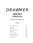
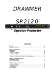
DRAWMER
MX50
DUAL DE-ESSER
OPERATORS MANUAL
CONTENTS
SAFETY CONSIDERATIONS
page 1
INTRODUCTION
page 2
INSTALLATION
•
Audio Connections
•
Power Connection
page 3
page 3
page 5
CONTROL DESCRIPTIONS and OPERATION
•
Linking
page 6
page 7
IF A FAULT DEVELOPS
page 8
CONTACTING DRAWMER
page 8
TECHNICAL SPECIFICATION
page 9
BLOCK DIAGRAM
page 10
SESSION RECALL
page 11
i
COPYRIGHT
This manual is copyrighted © 2011 by Drawmer Electronics, Ltd. With all rights
reserved. Under copyright laws, this manual may not be duplicated in whole or in part
without the written consent of Drawmer.
ONE YEAR LIMITED WARRANTY
Drawmer Electronics Ltd., warrants the Drawmer MX50 audio processor to conform
substantially to the specifications of this manual for a period of one year from the
original date of purchase when used in accordance with the specifications detailed
in this manual. In the case of a valid warranty claim, your sole and exclusive remedy
and Drawmer’s entire liability under any theory of liability will be to, at Drawmer’s
discretion, repair or replace the product without charge, or, if not possible, to refund
the purchase price to you. This warranty is not transferable. It applies only to the
original purchaser of the product.
For warranty service please call your local Drawmer dealer. Alternatively call
Drawmer Electronics Ltd. at +44 (0)1709 527574. Then ship the defective product,
with transportation and insurance charges pre-paid, to Drawmer Electronics Ltd.,
Coleman Street, Parkgate, Rotherham, S62 6EL UK. Write the RA number in large
letters in a prominent position on the shipping box. Enclose your name, address,
telephone number, copy of the original sales invoice and a detailed description of the
problem. Drawmer will not accept responsibility for loss or damage during transit.
This warranty is void if the product has been damaged by misuse, modification or
unauthorised repair.
THIS WARRANTY IS IN LIEU OF ALL WARRANTIES, WHETHER ORAL OR
WRITTEN, EXPRESSED, IMPLIED OR STATUTORY. DRAWMER MAKES NO
OTHER WARRANTY EITHER EXPRESS OR IMPLIED, INCLUDING, WITHOUT
LIMITATION, ANY IMPLIED WARRANTIES OF MERCHANTABILITY, FITNESS FOR
A PARTICULAR PURPOSE, OR NON-INFRINGEMENT. PURCHASER’S SOLE AND
EXCLUSIVE REMEDY UNDER THIS WARRANTY SHALL BE REPAIR OR
REPLACEMENT AS SPECIFIED HEREIN.
IN NO EVENT WILL DRAWMER ELECTRONICS LTD. BE LIABLE FOR ANY
DIRECT, INDIRECT, SPECIAL, INCIDENTAL OR CONSEQUENTIAL DAMAGES
RESULTING FROM ANY DEFECT IN THE PRODUCT, INCLUDING LOST PROFITS,
DAMAGE TO PROPERTY, AND, TO THE EXTENT PERMITTED BY LAW, DAMAGE
FOR PERSONAL INJURY, EVEN IF DRAWMER HAS BEEN ADVISED OF THE
POSSIBILITY OF SUCH DAMAGES.
Some states and specific countries do not allow the exclusion of implied warranties
or limitations on how long an implied warranty may last, so the above limitations may
not apply to you. This warranty gives you specific legal rights. You may have
additional rights that vary from state to state, and country to country.
In the interests of product development, Drawmer reserve the right to modify or
improve specifications of this product at any time, without prior notice.
ii
MX50 OPERATORS’ MANUAL
1
DRAWMER MX50
Dual De-Esser
SAFETY CONSIDERATIONS
CAUTION - MAINS FUSE
TO REDUCE THE RISK OF FIRE REPLACE THE MAINS FUSE ONLY WITH
THE SAME TYPE, WHICH MUST BE A CLASS 3, 230 VOLT, TIME DELAY
TYPE, RATED AT 63mA WHERE THE MAINS INPUT VOLTAGE SWITCH IS
SET TO 230 VOLTS AC. AND 125mA WHERE THE MAINS INPUT VOLTAGE
IS 115 VOLTS AC.
ALL FUSES MUST COMPLY WITH IEC 127-2.
THE FUSE BODY SIZE IS 20mm x 5mm.
CAUTION - MAINS CABLE
DO NOT ATTEMPT TO CHANGE OR TAMPER WITH THE SUPPLIED MAINS
CABLE.
CAUTION - SERVICING
DO NOT PERFORM ANY SERVICING. REFER ALL SERVICING TO
QUALIFIED SERVICE PERSONNEL.
WARNING
TO REDUCE THE RISK OF FIRE OR ELECTRIC SHOCK DO NOT EXPOSE
THIS EQUIPMENT TO RAIN OR MOISTURE.
2
MX50 OPERATORS’ MANUAL
INTRODUCTION
The MX50 is a flexible, simple to set up dual De-Esser designed to fulfil the needs of
professional studio, theatre and live sound applications. It may be used in balanced
systems at +4dBu operating levels using the XLR connectors, or unbalanced at -10dBu
using the TRS stereo jacks.
Though De-essers are most often used with the human voice, there are other instances
where a De-esser is a valuable asset to an engineer, for example, reducing the level of
overtones or string squeaks from acoustic guitars, or for making dynamic timbral
alterations to cymbal sounds. For example, too harsh crash cymbals could be
'de-middled' by suitably adjusting the frequency control.
The MX50 has two modes of operation, one in which it emulates a conventional full-band
de-esser, and a more sophisticated mode in which only that part of the spectrum
containing sibilant sounds is subjected to gain reduction. At its most basic, a De-esser
is a Limiter with a fast release time which reduces the overall signal level in response
to a precise band of frequencies, then recovers quickly. The upper cutoff frequency of
the sibilance band is generally around 8kHz and in the case of the MX50, the lower
cutoff is variable from 800Hz to 8kHz allowing the process to be optimised to various
voice types.
Even when working in this basic full-band mode, the MX50 provides extra features to
improve ease of control and flexibility. Specifically, the circuitry includes a floating
threshold system that adapts to the dynamics and level of the incoming signal, so no
manual threshold adjustment is necessary. De-essing is set via a single control and is
independent of signal levels over a 60dB range. Very low level signals, however, are not
subjected to de-essing as experimentation has shown that this produces the most
natural sounding result.
For more transparent de-essing, the Split Band mode confines the gain reduction
process to frequencies above those set by the Frequency control. Furthermore, as
sibilance rarely occurs above 10kHz, an additional Air switch has been fitted to add back
any frequencies in excess of 12kHz so as maintain maximum signal transparency at all
times. By using a combination of Split Band mode with the Air switch set to on, the
de-essing process can be made very transparent.
MX50 OPERATORS’ MANUAL
3
INSTALLATION
The MX50 is designed for standard 19" rack mounting and occupies 1U of rack space.
Avoid mounting the unit directly above power amplifiers or power supplies that radiate
significant amounts of heat. Always connect the mains earth to the unit. Use fibre or
plastic washers to prevent the front panel becoming marked by the mounting bolts.
AUDIO CONNECTIONS
Input and Output connections are provided for use at +4dBu via balanced XLRs or at
-10dBu via unbalanced jacks. It is permissible to use both +4dBu and -10dBu outputs
simultaneously. If unbalanced operation at +4dBu is required, simply connect the
unused terminal to Ground inside the XLR cable plugs. This applies to both inputs and
outputs. The wiring convention for XLR being: pin 1 Ground, pin 2 Hot and pin 3 Cold.
For use with unbalanced systems, the Cold pin 3 must be grounded at both input and
output XLRs.
Interference:
If the unit is to be used where it maybe exposed to high levels of
disturbance such as found close to a TV or radio transmitter, we
suggest that the unit be operated using the XLR connectors. The
screens of the signal cables should be connected to the chassis
connection on the XLR connector as opposed to connecting to
pin1. The MX50 fully conforms to the EMC standards.
Ground Loops:
If ground loop problems are encountered, never disconnect the
mains earth, but instead, try disconnecting the signal screen on
one end of each of the cables connecting the outputs of the MX50
to the patchbay. If such measures are necessary, balanced (XLR)
operation is recommended.
Level Conversion:
It is possible to apply an input to the MX50 at only one of the two
possible levels, say !10dB via the jack socket, and utilise both of
the output levels and cable options of !10dB and +4dB
simultaneously.
One useful example of this connection option would be if the unit
was used to process a keyboard - commonly these have an output
level of !10dB, and are terminated with jack sockets. It is feasible
using the MX50s dual output capability to use the !10dB jack input
to feed from the keyboard and the !10dB output onwards to the
amplifier, and the +4dB balanced XLR connector for a direct feed
to the mixing console. This removes the need for any DI box or
cable splitter. In this example, ground loop considerations may be
required.
4
MX50 OPERATORS’ MANUAL
AUDIO CONNECTION DIAGRAM
MX50 OPERATORS’ MANUAL
5
POWER CONNECTION
If, for some reason, the unit is to be operated at a mains input voltage which is different
to that as supplied, the following procedure must be carried out by a qualified technical
engineer.
1:
Disconnect the unit from the mains.
2:
Using a number 1 size pozidrive screwdriver, remove the seven
self-tapping screws that retain the top cover.
Removing seven screws to access internal fuse
3. Set the voltage rating and
replace the fuse.
4. Replace the cover.
6
MX50 OPERATORS’ MANUAL
CONTROL DESCRIPTION AND OPERATION
Both channels of the MX50 are identical and may be used completely independently or
linked for stereo operation. In the linked mode, the left and right channel control settings
are averaged, though the channel bypass switches remain independent. In linked mode,
both de-essers of the two channels track together to avoid the inevitable image shifting
that would occur if the stereo signal were treated independently.
Frequency
This control determines the lower range of the frequency band
used to detect sibilance and should ideally be set as high as
possible while still allowing the de-esser to react to sibilant
program sounds. This will vary from voice to voice, but will usually
be around 3 to 4kHz.
The control is continuously variable from 800Hz to 8kHz and
covers the full sibilant range, including the hard sounding
harmonics or other side effects that can be generated when treble
frequencies are boosted or enhanced in some way in an attempt to
add more definition to low frequency.
De-Ess
This rotary adjusts the amount of gain reduction that will take place
when a sibilant sound has been detected, up to a maximum of
20dB, this can be seen on the G.R. meter. Using large amounts of
gain reduction may cause very obvious artifacts, especially on
broadband mixes, so de-ess individual tracks where possible, and
choose Split Band mode for the least obtrusive processing.
This control uses floating threshold circuitry which tracks the signal
level so that the same setting can be used for signal levels over a
40dB range.
GR Display
Shows how much gain reduction is being applied. In Full Band
mode, the gain reduction is applied to the whole signal, while in
Split Band mode, only frequencies above the value set on the
Frequency control are attenuated.
Air
The AIR switch allows frequencies above the sibilant band (above
12kHz) to remain unaffected by De-Essing, thus preserving upper
harmonics and greatly increasing the transparency of signals
undergoing de-essing. Normally we would recommend leaving this
switch depressed (In).
MX50 OPERATORS’ MANUAL
7
De-Ess Band
Full
Reduces the total signal level in response to signals in the selected
frequency band. This mode of operation produces less phase
shifting of broadband material and single vocals but is more
noticeable then Split band processing. Applying excessive gain
reduction in this mode can lead to the vocal sound taking on a
lisping quality.
Split
Split band operation will only reduce the selected frequencies
above the value set via the frequency control, which in most
situations produces fewer audible side effects during de-essing.
This is particularly useful for reducing string noise on guitars,
breath noise on flute, or composite material.
Bypass
The Bypass position routes the input signal to the output with no
processing. These switches are independent of any linking and will
only bypass their respective channel.
Linking
Link
Depressing this switch configures the unit for stereo operation
where the average left/right signal level is used as the floating
threshold. The two individual channels must still be set up as in
mono operation. Usually they will be set the same, but in some
circumstances, it is permissible to use different settings i.e. when
sibilants are excessive on one channel of a stereo programme.
In linked mode, the red status Link LED will be illuminated.
Setup
Start with the controls set as follows, and adjust as necessary:Frequency -- Clockwise at 6KHz
De-Ess
-- Anticlockwise
Air
-- Out
Band
-- Full
Bypass
-- Out
Process some sibilant material and increase the De-ess control. You will notice that
frequencies around 8KHz produce reductions in signal level, which can be monitored
using the G.R display.
Adjust the frequency and de-ess controls for optimum results. Use the “Air” and “Split
Band” switches as necessary to get the most transparent results.
8
MX50 OPERATORS’ MANUAL
IF A FAULT DEVELOPS
For warranty service please call Drawmer Electronics Ltd. Or their nearest authorised
service facility, giving full details of the difficulty. On receipt of this information, service
or shipping instructions will be forwarded to you. No equipment should be returned
under the warranty without prior consent from Drawmer or their authorised
representative.
For service claims under the warranty agreement a service Returns Authorisation (RA)
number will be given. Write this RA number in large letters in a prominent position on
the shipping box. Enclose your name, address, telephone number, copy of the original
sales invoice and a detailed description of the problem.
Authorised returns should be prepaid and must be insured. All Drawmer products are
packaged in specially designed containers for protection. If the unit is to be returned,
the original container must be used. If this container is not available, then the equipment
should be packaged in substantial shock-proof material, capable of withstanding the
handling for the transit.
CONTACTING DRAWMER
Drawmer Electronics Ltd., will be pleased to answer all application questions to enhance
your usage of this equipment. Please address correspondence to:
Drawmer (Technical Help line) : Coleman St.: Parkgate : Rotherham : S62 6EL : UK
or, E-mail us on :
[email protected]
Drawmer dealers, Authorised service departments and other contact information can be
obtained from our web pages on
http://www.drawmer.com
MX50 OPERATORS’ MANUAL
9
TECHNICAL SPECIFICATIONS
(Measurements taken using +4dBu balanced XLR input where applicable)
INPUT IMPEDANCE
20KS (bal), 20KS (unbal)
MAXIMUM INPUT LEVEL
+21dBu
INPUT CMR
>!40dB
OUTPUT BALANCE
>!46dB
OUTPUT IMPEDANCE
50 S (bal), 100 S (unbal)
MAXIMUM OUTPUT LEVEL
+21dBu
BANDWIDTH
12Hz to 51KHz -1dB
CROSSTALK
@ 35KHz
!88dB
@ 1KHz
Below Noise Level
NOISE
Wideband
22Hz - 22KHz
ref +4dBu
(worst case)
AV
!89dB
!95dB
DISTORTION
Typical Input
100Hz
1KHz
10KHz
Unity Gain, +4dBu input
< 0.03%
< 0.02%
<0.03%
+14dBu input, 10dB Gain Red.
< 0.2%
< 0.2%
< 0.2%
POWER REQUIREMENTS
115Volt or 230Volt at 50-60Hz,
FUSE RATING
T63mA for 230Volt,
9 W atts
T125mA for 115Volt
CONFORMING TO IEC 127-2
FUSE TYPE
20mm x 5mm, Class 3 Slo-Blo, 250Volt working
CASE SIZE
482mm (w) x 44mm (h) x 200mm (d)
WEIGHT (incl packaging)
3.2 Kgs
10
MX50 OPERATORS’ MANUAL
BLOCK DIAGRAM
MX50 OPERATORS’ MANUAL
11