1
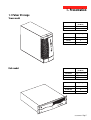
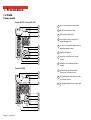
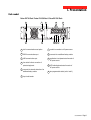
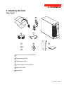
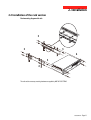
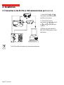
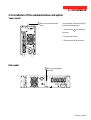
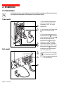
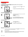
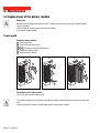
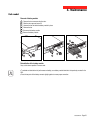
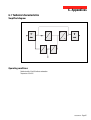
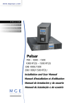
Pulsar EX
700 / 1000 / 1500
Installation and
user manual
e-mail: [email protected]
tel: 08-52 400 700 fax: 08-520 18121
51031604EN/AA
- Page 1
Introduction
Thank you for selecting an MGE UPS SYSTEMS product to protect your electrical equipment.
The Pulsar EX range has been designed with the utmost care. We recommend that you take the time to read this manual
to take full advantage of the many features of your UPS.
MGE UPS SYSTEMS pays great attention to the environmental impact of its products. Measures that have made Pulsar
EX a reference in environmental protection include:
◗ the eco-design approach used in product development;
◗ recycling of Pulsar EX at the end of its service life.
To discover the entire range of MGE UPS SYSTEMS products and the options available for the Pulsar EX range, we invite
you to visit our web site at www.mgeups.com or contact your MGE UPS SYSTEMS representative.
Page 2 - 51031604EN/AA
Safety
Safety rules
Safety of persons
A UPS has its own internal power source (the battery). Consequently, the power outlets may be energised even if the UPS
is disconnected from the AC-power source.
Dangerous voltage levels are present within the UPS. It should be opened exclusively by qualified service
personnel.
The UPS must be properly earthed. Measurements are required to ensure that the total leakage current of the UPS
and the protected equipment does not exceed 3.5 mA.
The battery supplied with the UPS contains small amounts of toxic materials. To avoid accidents, the directives
listed below must be observed:
◗ Never burn the battery (risk of explosion).
◗ Do not attempt to open the battery (the electrolyte is dangerous for the eyes and skin).
◗ Comply with all applicable regulations for the disposal of the battery.
◗ Batteries constitute a danger (electrical shock, burns). The short-circuit current may be very high. Precautions
must be taken for all handling.
Product safety
UPSs must be connected to a nearby wall outlet that is easily accessible.
The UPS can be disconnected from the AC-power source by removing the power cord.
◗ Never install the UPS near liquids or in an excessively damp environment.
◗ Never let a foreign body penetrate inside the UPS.
◗ Never block the ventilation grates of the UPS.
◗ Never expose the UPS to direct sunlight or a source of heat.
Special precautions
The UPS connection instructions contained in this manual must be followed in the indicated order.
Check that the indications on the rating plate correspond to your AC-power system and to the actual electrical consumption
of all the equipment to be connected to the UPS.
If the UPS must be stored prior to installation, storage must be in a dry place.
The admissible storage temperature range is -20° C to +45° C.
If the UPS remains de-energised for a long period, we recommend that you energise the UPS for a period of 24 hours, at
least once every month. This charges the battery, thus avoiding possible irreversible damage.
Prior to handling the battery:
◗ remove all watches, rings, bracelets and any other metal objects;
◗ use tools with insulated handles.
51031604EN/AA
- Page 3
Foreword
Using this document
Information may be found primarily by consulting:
◗ the contents,
◗ the index.
Pictograms
Important instructions that must always be followed.
Information, advice, help.
Visual indication.
Action.
Audio indication.
In the illustrations on the following pages, the symbols below are used:
LED off.
LED on.
LED flashing.
Page 4 - 51031604EN/AA
Contents
1.
Presentation
1.1
Pulsar EX range .......................................................................................................................... 7
Tower model .................................................................................................................................... 7
Rack model ..................................................................................................................................... 7
1.2
Back ............................................................................................................................................. 8
Tower model .................................................................................................................................... 8
Rack model ..................................................................................................................................... 9
1.3
2.
Control panel ............................................................................................................................... 10
Installation
2.1
Unpacking and checks ............................................................................................................... 11
Tower model .................................................................................................................................. 11
Rack model ................................................................................................................................... 12
2.2
Installation of the rack version .................................................................................................. 13
2.3
Connection to the RS 232 or USB communications port (optional) ........................................ 14
2.4
Installation of the communications-card option ...................................................................... 15
Tower model .................................................................................................................................. 15
Rack model ................................................................................................................................... 15
2.5
Connections ................................................................................................................................ 16
Tower model .................................................................................................................................. 16
Rack model ................................................................................................................................... 16
3.
Operation
3.1
Start-up ........................................................................................................................................ 17
3.2
Bargraph indications .................................................................................................................. 17
3.3
Operation on battery power (following failure of AC input power) ............................................. 18
Transfer to battery power .............................................................................................................. 18
Threshold for the low-battery warning ........................................................................................... 18
End of backup time ....................................................................................................................... 18
Sleep mode ................................................................................................................................... 18
51031604EN/AA
- Page 5
Contents
3.4
Personalisation (optional) ........................................................................................................... 19
Function ........................................................................................................................................ 19
"ON / OFF conditions" tab ............................................................................................................. 19
"Battery" tab .................................................................................................................................. 19
"Output" tab ................................................................................................................................... 20
"Bypass" tab .................................................................................................................................. 20
3.5
4.
Shutdown ..................................................................................................................................... 20
Maintenance
4.1
Troubleshooting .......................................................................................................................... 21
4.2
Replacement of the battery module .......................................................................................... 22
Tower model .................................................................................................................................. 22
Rack model ................................................................................................................................... 23
5.
Environment ............................................................................................................. 24
6.
Appendices
6.1
Technical characteristics ........................................................................................................... 25
Simplified diagram ........................................................................................................................ 25
Operating conditions ..................................................................................................................... 25
Page 6 - 51031604EN/AA
6.2
Glossary ....................................................................................................................................... 26
6.3
Index ............................................................................................................................................. 27
1. Presentation
1.1 Pulsar EX range
Tower model
Dimensions in mm
(H x W x D)
EX 700 / EX 1000
235.5 x 145 x 400
EX 1500
235.5 x 145 x 505
Weight in kg
EX 700
10
EX 1000
12
EX 1500
15
Rack model
Dimensions in mm
(H x W x D)
EX 700 Rack
88 (2U) x 482.6 x 430
EX 1000 Rack
88 (2U) x 482.6 x 430
EX 1500 Rack
88 (2U) x 482.6 x 493
Weight in kg
EX1000
EX 700 Rack
14
EX 1000 Rack
16
EX 1500 Rack
20
Rack
51031604EN/AA
- Page 7
1. Presentation
1.2 Back
Tower model
Pulsar EX 700 / Pulsar EX 1000
1
RS232
USB
2
3
4
5
1
slot for communications-card option.
2
RS232 communications port.
3
USB communications port.
4
four outlets for direct connection of
protected equipment.
5
connector for automatic detection of an
additional battery module.
6
input circuit breaker.
7
socket for connection to AC-power
source.
8
connector for an additional battery
module.
9
pushbutton to test phase/neutral
inversion of AC-power source.
6
1
7
2
8
9
10
11
Pulsar EX 1500
1
RS232
USB
2
3
10 LED indicating phase/neutral inversion
of AC-power source.
4
11 two programmable outlets (outlet 1 and
2).
5
1
8
9
2
10
6
7
11
Page 8 - 51031604EN/AA
1. Presentation
Rack model
Pulsar EX 700 Rack / Pulsar EX 1000 Rack / Pulsar EX 1500 Rack
3
7
1
4
11
USB
1
2
RS232
2
6
10 9
5
8
1
slot for communications-card option.
7
socket for connection to AC-power source.
2
RS232 communications port.
8
connector for an additional battery module.
3
USB communications port.
9
pushbutton to test phase/neutral inversion of
AC-power source.
4
four outlets for direct connection of
protected equipment.
5
6
connector for automatic detection of an
additional battery module.
10 LED indicating phase/neutral inversion of
AC-power source.
11 two programmable outlets (outlet 1 and 2).
input circuit breaker.
51031604EN/AA
- Page 9
1. Presentation
1.3 Control panel
Alarms
%
% battery ␣ ␣ ␣ ␣ ␣
remaining
% load
100%
100%
13 electronics fault.
80%
80%
50%
14 battery fault.
50%
50%
20%
15
20%
20%
100%
12 UPS overload.
80%
%
16 hold down to display percent load:
- lamp test or buzzer OFF.
test
17 - forced transfer to bypass and back
by pressing button 3 times in less than
5 seconds.
1
18 status of programmable outlet 1:
Supplied with power
2
19 status of programmable outlet 2:
Status change in
progress.
by-pass
20
operation on bypass
(no backup power available).
21
operation in ON-LINE mode
(backup power available).
22 operation on battery power.
23 ON / OFF.
Page 10 - 51031604EN/AA
2. Installation
2.1 Unpacking and checks
Tower model
24
25
26
27
28
29
24 two cords for connection of the protected equipment.
25 RS 232 communications cable.
26 USB communications cable.
27 "UPS Driver" diskette for UPS personalisation.
28 "Solution Pac" CD ROM.
29 documentation.
51031604EN/AA
- Page 11
2. Installation
Rack model
24
00 Rack
EX10
24
27
25
26
28
␣ 24 two cords for connection of the protected equipment.
␣ 25 RS 232 communications cable.
␣ 26 USB communications cable.
␣ 27 "UPS Driver" diskette for UPS personalisation.
␣ 28 "Solution Pac" CD ROM.
␣ 29 documentation.
␣ 30 telescopic rails for mounting in 19" bay with mounting hardware.
Page 12 - 51031604EN/AA
29
30
2. Installation
2.2 Installation of the rack version
Rack mounting diagram with rails.
1
3
3
3
4
3
2
k
Rac
000
EX1
The rails and the necessary mounting hardware are supplied by MGE UPS SYSTEMS.
51031604EN/AA
- Page 13
2. Installation
2.3 Connection to the RS 232 or USB communications port (optional)
1 - Connect the RS 232 25 or USB 26
communications cable to the serial port or
the USB port on the computer.
25
RS232
2
USB
3
26
2 - Connect the other end of the
communications cable 25 or 26 to the RS
232 2 or USB 3 communications port
on the UPS.
The UPS can now communicate with all
MGE UPS SYSTEMS supervision, set-up or
safety software.
3
2
The RS 232 and USB communications ports cannot operate simultaneously.
Page 14 - 51031604EN/AA
2. Installation
2.4 Installation of the communications-card option
Tower model
1 Slot for the communications-card
It is not necessary to shut down the UPS to
install the communications card:
option.
U-Talk
USB
1 - Remove the slot 1 cover secured by
two screws.
2 - Insert the card in the slot.
3 - Secure the card with the two screws.
1
2
Rack model
1 Slot for the communicationscard option.
USB
1
2
RS232
51031604EN/AA
- Page 15
2. Installation
2.5 Connections
Check that the indications on the rating plate on the back of the UPS correspond to your AC-power system and to
the actual electrical consumption of all the equipment to be connected to the UPS.
Tower model
4
7
es
p
e
1
2
24
11
Rack model
7
4
2
1
11
24
Page 16 - 51031604EN/AA
2 - Connect the cord to the AC-power socket
␣ ␣ 7 , then to the AC-power wall outlet.
r
t
s
res
?
1 - Remove the power cord supplying the
equipment to be protected. Check cord
characteristics (> 250 V, 10 A, see the
technical sheet).
3 - Connect the protected equipment to the
UPS using the two cords 24 . It is advised to
connect priority loads to the four outlets 4
and any non-priority loads to the two
programmable outlets 11 (If the UPS is
connected to a computer running MGE
communications software, it is possible to
program the interruption of power to the two
programmable outlets 11 during operation
on battery power, thus reserving backup
power for the priority loads).
As soon as the UPS is energised,
the battery begins charging. Eight
hours are required to charge to the
full rated backup time.
3. Operation
3.1 Start-up
The protected equipment connected to the UPS can be energised, whether AC input power is available or not.
21
22
Press the ON / OFF button 23 .
The buzzer beeps and all the LEDs go ON.
The buzzer beeps twice, then:
- If AC input power is available, LED 21 goes ON, indicating operation
in ON-LINE mode.
- If AC input power is not available and the UPS is configured for
automatic restart mode, the buzzer beeps three times and LED 22 goes
ON, signalling operation on battery power.
23
All connected equipment is energised.
If LEDs 21 or 22 do not go ON or if LEDs 12 to 14 flash,
there is a fault (see section 4.1).
3.2 Bargraph indications
LEDs 12 to 15 provide three different indications:
%
100%
80%
12
13
50%
20%
16
test
18
1
2
19
by-pass
2 - Percent load drawn by the protected equipment, when button 16 is
pressed.
14
15
%
1 - Remaining backup time in percent (during normal operation).
3 - Operating faults (flashing LED and beeps):
␣ 12 Overload.
␣ 13 UPS fault.
␣ 14 Battery fault.
Status LEDs 18 and 19 for programmable outlets 1 and 2:
- LEDs OFF: the outlets are not supplied with power.
- LEDs flashing: status change in progress.
- LEDs ON: the outlets are supplied with power.
Outlets 1 and 2 can be remotely programmed and controlled. They may
be used for sequential start-up of the protected applications, shedding of
non-priority applications during operation on battery power, and priority
management at the end of battery backup time to reserve the longest
possible backup time for the most sensitive applications. These outlets
are programmed using Solution Pac software.
51031604EN/AA
- Page 17
3. Operation
3.3 Operation on battery power (following failure of AC input power)
Transfer to battery power
The AC-power source is outside tolerances, LED 23 is ON, the buzzer
beeps three times.
1
2
The equipment connected to the UPS is supplied by the battery.
by-pass
22
Threshold for the low-battery warning
The low-battery warning threshold can be set by the user, with the "UPS
Driver" software (see section 3.4).
LED 22 flashes.
The buzzer beeps every three seconds.
1
2
by-pass
22
There is very little remaining battery backup time. Close all
applications because UPS automatic shutdown is imminent.
End of backup time
The buzzer sounds continuously.
Press button 17 to turn the buzzer OFF.
%
test
17
The equipment is no longer supplied with power.
1
2
by-pass
Sleep mode
The UPS goes to sleep mode at the end of the battery backup time (LEDs 12 to 15 ON) until complete shutdown due to
tripping of the battery-protection function against deep discharge.
Return of AC input power:
If, in spite of the return of AC input power, the UPS does not restart, check that the automatic-restart function
(activated by return of AC input power) has not been disabled (see section 3.4).
Page 18 - 51031604EN/AA
3. Operation
3.4 Personalisation (optional)
Function
Personalisation parameters can be set and modified using the "UPS Driver" software installed on a computer that is
connected to the UPS (see section 2.3 Connection to the RS 232 (or USB) communications port).
Check that the RS 232 25 or USB 26 cable is properly connected.
"UPS Driver" installation:
1 - Insert the "UPS Driver" diskette in the drive of a PC running Windows.
2 - Select the disk drive (A:\).
3 - Double-click "upsdriv.exe".
Once "UPS Driver" has been installed, UPS parameters can be modified in a window containing a number of tabs, each
presenting a set of parameters.
"ON / OFF conditions" tab
Personalisable function
Default setting
Options
Automatic start
Enabled
Disabled
Cold start (battery power)
Enabled
Disabled
Forced shutdown
Enabled
Disabled
Sleep mode
Disabled
Enabled
UPS ON / OFF via software
Enabled
Disabled
Personalisable function
Default setting
Options
Automatic "Battery test" intervals
Every day
Once a week
Once a month
No test
"Battery" tab
"Low-battery warning" threshold
20% remaining battery backup time 40% remaining battery backup time
51031604EN/AA
- Page 19
3. Operation
"Output" tab
Personalisable function
Default setting
Options
Rated UPS voltage
230 V
200 V - 208 V - 220 V - 240 V
Rated UPS frequency
F = 50 Hz
60 Hz
UPS tolerance for AC-power
source frequency
F ± 5%
F ± 1% to ± 10%, in 1% steps
Overload alarm threshold
110%
0 to 110%, in 10% steps
UPS restart following short-circuit
Disabled
Enabled (click to add check)
Personalisable function
Default setting
Options
Transfer to bypass if overload
Enabled
Disabled (click to remove check)
Transfer to bypass following a fault, whatever the
conditions on the AC-power source
Disabled
Enabled (click to add check)
"Bypass" tab
3.5 Shutdown
by-pass
Press button 23 (return to the OFF position).
The connected equipment is no longer supplied with power.
23
Page 20 - 51031604EN/AA
4. Maintenance
4.1 Troubleshooting
If any of LEDs 12 , 13 or 14 flash, there is a operating anomaly or an alarm.
If a LED flashes, the bargraph data is no longer displayed.
Troubleshooting not requiring MGE UPS SYSTEMS after-sales support
Indication
Signification
Correction
LED 12 flashes and the
buzzer beeps.
UPS overload. Overload is too long or too high.
Check the power drawn by the
The buzzer sounds continuously.
equipment and disconnect any non◗ If AC power is present and within tolerances, the UPS priority devices.
goes to bypass mode (supply directly by the AC-power
source). LED 20 flashes.
◗ If AC power is not present or not within tolerances,
the connected applications are no longer supplied.
LED 14 flashes.
A battery fault was detected during the automatic
battery test.
Connect that the battery connector
is fully pushed in.
◗ Replace battery module (see the
Maintenance section).
◗
Troubleshooting requiring MGE UPS SYSTEMS after-sales support
Indication
Signification
LED 13 flashes and the
buzzer sounds
continuously.
UPS electronics have detected a UPS fault.
Depending on the UPS personalisation parameters
(see section 3.4), there are two possibilities:
◗ the equipment connected to the UPS continues to be
supplied, but directly from the AC-power source (via
the automatic bypass (LED 20 ON);
◗ the connected equipment is no longer supplied.
Correction
Call the after-sales support
department.
The equipment connected to the UPS is no
longer protected.
51031604EN/AA
- Page 21
4. Maintenance
4.2 Replacement of the battery module
Safety rules:
Batteries constitute a danger (electrical shock, burns). The short-circuit current may be very high. Precautions must be
taken for all handling:
◗ remove all watches, rings, bracelets and any other metal objects;
◗ use tools with insulated handles.
Tower model
Removal of battery module
A
B
C
F
G
- Press to open door.
- Slide the door open and remove it.
D E - Procedure to remove the protective cover.
- Disconnect the battery module.
- Remove the battery module.
F
B
C
G
D
A
E
Reinstallation of the battery module
Carry out the above operation in reverse order.
◗ To maintain an identical level of performance and safety, use a battery module identical to that previously mounted in the
UPS.
◗ Press the two parts of the battery connector tightly together to ensure proper connection.
Page 22 - 51031604EN/AA
4. Maintenance
Rack model
Removal of battery module
A
B
C
D
E
F
- Remove the two screws securing the door.
- Slide the door open and remove it.
- Unscrew the bar that holds the battery module in place.
- Remove the bar.
- Disconnect the battery module.
- Remove the battery module.
E
C
B
A
D
F
Reinstallation of the battery module
Carry out the above operation in reverse order.
◗ To maintain an identical level of performance and safety, use a battery module identical to that previously mounted in the
UPS.
◗ Press the two parts of the battery connector tightly together to ensure proper connection.
51031604EN/AA
- Page 23
5. Environment
This product has been designed to respect the environment:
It does not contain CFCs or HCFCs.
UPS recycling at the end of service life:
MGE UPS SYSTEMS undertakes to recycle, by certified companies and in compliance with all applicable regulations, all
UPS products recovered at the end of their service life (contact your MGE branch office).
Packing:
UPS packing materials must be recycled in compliance with all applicable regulations.
Warning:
This product contains lead-acid batteries. Lead is a dangerous substance for the environment if it is not properly recycled
by specialised companies.
Web site: www.mgeups.com
Page 24 - 51031604EN/AA
6. Appendices
6.1 Technical characteristics
Simplified diagram
Operating conditions
Relative humidity: 20 to 90% without condensation.
Temperature: 0 to 40° C.
51031604EN/AA
- Page 25
6. Appendices
6.2 Glossary
Authorised voltage range for
transfer to bypass if fault or
overload
Upper and lower voltage thresholds within which the UPS can operate on the automatic
bypass in the event of a UPS fault or overload.
Automatic bypass
Automatic switch controlled by the UPS, used to connect the equipment directly to the
AC-power source in the event of a UPS failure or an overload.
Automatic start following
return of AC input power
This function automatically starts the UPS when AC input power returns following
shutdown at the end of the battery backup time. It can be enabled or disabled.
Backup time
Time that the connected equipment can operate on battery power.
Bargraph
Device on the front panel indicating the percent remaining backup time or the percent
load.
Battery test
Internal UPS test on battery status.
Dialog box
A window in a computer program displayed for selection by the user of various options
and parameter settings.
Double conversion
The power supplied to the connected equipment is completely regenerated by
continuous double conversion, i.e. the AC power from the AC-power source is rectified
(AC - DC), then converted back (DC - AC) to AC power.
Equipment
Devices or systems connected to the UPS output.
Forced shutdown
Ten-second interruption in the supply of power to the connected equipment following a
system shutdown, even if AC input power returns during the interruption period.
Percent load
Ratio between the power drawn by the connected equipment and the total power that
the UPS can supply.
Personalisation
A number of UPS functions can be modified using the «UPS Driver» software to better
meet the user’s needs.
Programmable outlets
Outlets that can be automatically shed during operation on battery power (a shedding
time delay may be programmed using Solution-Pac software.
Start on battery power
This function makes it possible to energise the connected equipment even when AC
input power is not available (operation exclusively on battery power).
UPS
Uninterruptible Power Supply
UPS ON / OFF via software
It is possible to enable or disable use of UPS ON / OFF controls by the computersystem protection software.
Page 26 - 51031604EN/AA
6. Appendices
6.3 Index
A
M
AC power
Failure .................................................................... 18
Frequency tolerance ............................................... 20
Return ..................................................................... 18
Automatic start ............................................................... 19
Mode
ON LINE mode ....................................................... 10
B
Bargraph ................................................................... 10-17
Battery
Battery test ............................................................. 19
End of backup time ................................................. 18
Fault .................................................................. 10-17
Handling precautions ................................................ 3
Low-battery warning ............................................... 19
Recycling ............................................................. 3-24
Replacement ..................................................... 22-23
Transfer to battery power ....................................... 18
Buttons ..................................................................... 8-9-10
Buzzer ....................................................................... 17-18
Bypass
Automatic bypass ......................................... 10-20-21
C
Communication .................................................. 8-9-14-15
Connection
Additional battery module ...................................... 8-9
Communications card ............................................. 14
RS 232 communications port ................................. 14
USB communications port ...................................... 14
O
Overload ............................................................. 10-20-21
S
Safety ............................................................................... 3
Shutdown
Buzzer .............................................................. 10-18
Forced shutdown .................................................... 19
UPS ON / OFF via software ................................... 19
UPS shutdown .................................................. 10-20
Sleep mode .............................................................. 18-19
Automatic restart .............................................. 19-20
Software
UPS Driver ............................................................. 19
Start-up .......................................................................... 17
T
Technical characteristics ................................................ 25
Temperature
Excessive ambient temp. ....................................... 25
Transfer (forced) ........................................................... 10
U
UPS Driver .................................................................... 19
UPS fault ............................................................. 10-17-20
UPS storage .................................................................... 3
D
Dimensions ...................................................................... 7
W
E
Web site ........................................................................... 2
Weight .............................................................................. 7
Environnement ......................................................... 2-3-24
F
Fault (UPS) .......................................................... 10-17-21
L
LEDs ....................................................................... 8-9-10
Lamp test ................................................................ 10
51031604EN/AA
- Page 27
Page 28 - 51031604EN/AA