1
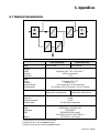
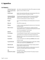
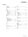
MGE UPS SYSTEMS
www.mgeups.com
Pulsar EXtreme
2200C / 3200C
Installation and user
manual
P
P
O
W
E
D E R
V I
O
R
R
T H E
U N
I N
T E
R
R
U
P
T
I
B
L
E
34007532EN/AA
- Page 1
Introduction
Thank you for selecting an MGE UPS SYSTEMS product to protect your electrical equipment.
The Pulsar EXtreme C range has been designed with the utmost care. We recommend that you take the time to read this
manual to take full advantage of the many features of your UPS.
MGE UPS SYSTEMS pays great attention to the environmental impact of its products. Measures that have made
Pulsar EXtreme C a reference in environmental protection include:
◗ the eco-design approach used in product developmen,
◗ recycling of Pulsar EXtreme C at the end of its service life.
To discover the entire range of MGE UPS SYSTEMS products and the options available for the Pulsar EXtreme C range,
we invite you to visit our web site at www.mgeups.com or contact your MGE UPS SYSTEMS representative.
Page 2 - 34007532EN/AA
Foreword
Using this document
Information may be found primarily by consulting:
◗ the contents,
◗ the index.
Pictograms
Important instructions that must always be followed.
Information, advice, help.
Visual indication.
Action.
Audio indication.
In the illustrations on the following pages, the symbols below are used:
LED off.
LED on.
LED flashing.
34007532EN/AA
- Page 3
Page 4 - 34007532EN/AA
Contents
1.
Presentation
1.1
Standard positions ....................................................................................................................... 7
Rack position .................................................................................................................................. 7
Tower position ................................................................................................................................. 7
1.2
Back ............................................................................................................................................... 8
Pulsar EXtreme 2200C .................................................................................................................. 8
Pulsar EXtreme 3200C .................................................................................................................. 8
Pulsar EXB 2200 / 3200 ................................................................................................................. 8
1.3
2.
3.
Control panel ................................................................................................................................. 9
Installation
2.1
Unpacking and checks ............................................................................................................... 10
2.2
Installation in rack position ....................................................................................................... 11
2.3
Installation in tower position ..................................................................................................... 12
2.4
Connection to the RS232 or USB communications port (optional) ......................................... 13
2.5
Installation of the communications-card option ...................................................................... 13
2.6
Connections ................................................................................................................................ 14
operation
3.1
Start-up ........................................................................................................................................ 15
3.2
Bargraph indications .................................................................................................................. 15
3.3
Operation on battery power (following failure of AC input power) ............................................. 16
Transfer to battery power .............................................................................................................. 16
Threshold for the low-battery warning ........................................................................................... 16
End of backup time ....................................................................................................................... 16
3.4
Personalisation (optional) ........................................................................................................... 17
Function ........................................................................................................................................ 17
"ON / OFF conditions" tab ............................................................................................................. 17
"Battery" tab .................................................................................................................................. 17
"Output" tab ................................................................................................................................... 18
"Bypass" tab .................................................................................................................................. 18
3.5
UPS Shutdown ............................................................................................................................ 18
3.6
UPS remote power off ................................................................................................................ 19
34007532EN/AA
- Page 5
Contents
4.
5.
6.
Page 6 - 34007532EN/AA
Maintenance
4.1
Troubleshooting .......................................................................................................................... 20
4.2
Replacement of the battery module .......................................................................................... 22
Environment ..................................................................................................................................... 24
Appendices
6.1
Technical characteristics ........................................................................................................... 25
6.2
Glossary ....................................................................................................................................... 26
6.3
Index ............................................................................................................................................. 27
1. Presentation
1.1 Standard positions
Rack position
438 mm (19")
654 mm
86.5 mm
(2U)
P U L S A R
EXtreme
BYPASS
2
1
test
%
100%
20% 50% 80%
%
www.mgeups.com
Pulsar EXtreme 2200C: 35.3 Kg
Pulsar EXtreme 3200C: 35.7 Kg
BYPASS
2
1
test
%
20% 50% 80% 100%
%
Tower position
P U L S A R
EXtrem e
www.mgeups.com
34007532EN/AA
- Page 7
1. Presentation
1.2 Back
Pulsar EXtreme 2200C
3
8
2
9 10 11 12
5
1
4
1
Slot for communications-card option.
2
RS232 communications port.
3
USB communications port.
4
Four outlets for direct connection of
protected equipment.
5
Two programmable outlets
(outlet 1 and 2).
6
Output circuit breakers.
7
Socket for connection to AC-power
source.
8
Connector for an additional battery
module.
9
Connector for automatic detection of an
additional battery module.
7
Pulsar EXtreme 3200C
3
8
2
5
Pulsar EXB 2200 / 3200
14
15
6
9 10 11 12
4
1
7
10 Pushbutton to test phase/neutral
inversion of AC-power source.
11 LED indicating phase/neutral inversion
of AC-power source.
12 Connector for remote power off.
13 Battery module connectors (to the UPS
or to other battery modules).
14 Connectors for automatic detection of
additional battery modules.
13
13
15 Circuit breaker for battery ON/OFF and
protection.
Page 8 - 34007532EN/AA
1. Presentation
1.3 Control panel
16
17
18
1
2
BYPASS
19
20
21
16
ON / OFF.
17
Operation on battery power.
18
Operation in ON-LINE mode (backup power available).
test
%
22
23
24
Alarms
19
Operation on bypass (no backup power available).
20
Status of programmable outlet 2:
Supplied with power.
%
20% 50% 80% 100%
27 UPS
25
26
27
%
battery
remaining
%
load
100%
100%
80%
80%
50%
50%
20%
20%
overload
21
Status of programmable outlet 1:
Status change in
progress.
26 Electronics
fault
22
Lamp test or buzzer OFF.
Forced transfer to bypass and back
by pressing button 3 times in less
than 5 seconds.
◗
◗
23
Hold down to display
percent load:
(*) :
◗
◗
Press simultaneously at
least 3 seconds to reset
the “End of battery life”
alarm.
25 Battery
fault *
24
flashing LED + buzzer: battery fault (battery must be replaced).
flashing LED + long buzzer (once per hour): theoretical end of battery life (replacement recommended).
34007532EN/AA
- Page 9
2. Installation
2.1 Unpacking and parts check
30
28
29
31
20% 50% 80% 100%
%
32
BYPASS
2
1
test
%
33
34
www.mgeups.com
P U L S A R
EXtreme
35
28 Cord for connection to the AC-power source for Pulsar EXtreme 3200C versions only
(for the Pulsar EXtreme 2200C version, use the power cord of the protected equipment).
29 Two cords for connection of the protected equipment.
30 RS232 communications cable.
31 USB communications cable.
32 Telescopic rails for mounting in 19" bay with mounting hardware.
33 Securing system for equipment power cords.
34 CD-ROM with the Solution-Pac and UPS Driver software.
35 Product documentation.
36 Two supports for the upright position.
Page 10 - 34007532EN/AA
36
2. Installation
2.2 Installation in rack position
Follow steps 1 to 6 for rack mounting of the UPS on the rails.
1
2
2
2
4
2
3
6
%
2
1
100%
80%
50%
20%
BYPASS
%
test
3
5
The rails and the necessary mounting hardware are supplied by MGE UPS SYSTEMS.
Note for step 3: It is possible to adjust the positions of the front brackets.
34007532EN/AA
- Page 11
2. Installation
2.3 Installation in tower position
BYPASS
2
1
test
%
20% 50% 80% 100%
%
Connect the two supports for the upright position.
www.mgeups.com
om
www.mgeups.c
P U L S A R
EXtreme
P U L S A R
EXtreme
Page 12 - 34007532EN/AA
2. Installation
2.4 Connection to the RS232 or USB communications port (optional)
1 - Connect the RS232 30 or USB 31
communications cable to the serial port or
the USB port on the computer.
30
2 - Connect the other end of the
communications cable 30 or 31 to the
RS232 2 or USB 3 communications
port on the UPS.
31
The UPS can now communicate with all
MGE UPS SYSTEMS supervision, set-up or
safety software.
3
2
The RS232 and USB communications ports cannot operate simultaneously.
2.5 Installation of the communications-card option
Slot for the
communicationscard option.
1
It is not necessary to shut down the UPS to
install the communications card:
1 - Remove the slot 1 cover secured by
two screws.
2 - Insert the card in the slot.
3 - Secure the card with the two screws.
34007532EN/AA
- Page 13
2. Installation
2.6 Connections
Check that the indications on the rating plate on the back of the UPS correspond to your AC-power system and to
the actual electrical consumption of all the equipment to be connected to the UPS.
7
28
29
4
5
33
1 - Remove the power cord supplying the
equipment to be protected.
2 - Pulsar EXtreme 2200C: connect the
power cord (1) just removed from the
equipment to the AC-power socket 7 and
then to the AC-power wall outlet.
- Pulsar EXtreme 3200C: connect the
supplied power cord 28 (250 V, 16 A) to the
AC-power socket 7 and then to the ACpower wall outlet.
3 - Connect the protected equipment to the
UPS using the two cords 29 . It is advised to
connect priority loads to the four outlets 4
and any non-priority loads to the two
programmable outlets 5 (If the UPS is
connected to a computer running MGE UPS
SYSTEMS communications software, it is
possible to program the interruption of power
to the two programmable outlets 5 during
operation on battery power, thus reserving
backup power for the priority loads).
4 - Lock the connections using the securing
system 33 .
As soon as the UPS is energised,
the battery begins charging. Eight
hours are required to charge to the
full rated backup time.
(1) Make sure the cord has the following
characteristics: 250 V, 10 A, cross-sectional
area 1 mm2, type HO5.
Page 14 - 34007532EN/AA
3. Operation
3.1 Start-up
The protected equipment connected to the UPS can be energised, whether AC input power is available or not.
BYPASS
2
Caution: the AC input power source must be present when energising
for the first time.
Press the ON / OFF button 16 .
The buzzer beeps and all the LEDs go ON.
The buzzer beeps twice, then:
◗ If AC input power is available, LED 18 goes ON, indicating operation
in ON-LINE mode.
◗ If AC input power is not available and the UPS is configured for
automatic restart mode, the buzzer beeps three times and LED 17 goes
ON, signalling operation on battery power.
1
test
%
100%
20% 50% 80%
%
All connected equipment is energised.
16 17 18 25 26 27
If LEDs 17 or 18 do not go ON or if LEDs 25 to 27 flash, there is a
fault (see section 4.1).
3.2 Bargraph indications
BYPASS
2
LEDs 24 to 27 provide three
different indications:
1
test
16
17 18
19
20 21
22
%
23
20% 50% 80% 100%
%
24 25 26 27
1 - Remaining backup time in percent
(during normal operation).
2 - Percent load drawn by the protected
equipment, when button 23 is pressed.
3 - Operating faults (flashing LED and
beeps):
27 Overload.
26 UPS fault.
25 Battery fault or end-of-life warning.
Status LEDs 20 and 21 for programmable outlets 1 and 2:
LEDs OFF: the outlets are not supplied with power.
LEDs flashing: status change in progress.
◗ LEDs ON: the outlets are supplied with power.
Outlets 1 and 2 can be remotely programmed and controlled. They may
be used for sequential start-up of the protected applications, shedding of
non-priority applications during operation on battery power, and priority
management at the end of battery backup time to reserve the longest
possible backup time for the most sensitive applications. These outlets
are programmed using Solution Pac software.
◗
◗
34007532EN/AA
- Page 15
3. Operation
3.3 Operation on battery power (following failure of AC input power)
Transfer to battery power
BYPASS
2
The AC-power source is outside tolerances, LED 17 is ON, the buzzer
beeps three times.
1
The equipment connected to the UPS is supplied by the battery.
test
17
Threshold for the low-battery warning
BYPASS
2
The low-battery warning threshold can be set by the user, with the UPS
Driver software (see section 3.4).
LED 17 flashes.
The buzzer beeps every three seconds.
1
test
%
17
There is very little remaining battery backup time. Close all
applications because UPS automatic shutdown is imminent.
End of backup time
BYPASS
2
The buzzer sounds continuously.
Press button 22 to turn the buzzer OFF.
1
The equipment is no longer supplied with power.
test
%
22
The UPS goes to sleep mode at the end of the battery backup time until complete shutdown due to tripping of the batteryprotection function against deep discharge.
Return of AC input power:
If, in spite of the return of AC input power, the UPS does not restart, check that the automatic-restart function
(activated by return of AC input power) has not been disabled (see section 3.4).
Page 16 - 34007532EN/AA
3. Operation
3.4 Personalisation (optional)
Function
Personalisation parameters can be set and modified using the UPS Driver software installed on a computer that is
connected to the UPS (see section 2.4 Connection to the RS232 communications port).
Check that the RS232 30 cable is properly connected.
UPS Driver installation:
1 - Insert the Solution-Pac CD-ROM containing the UPS Driver software in the computer drive.
2 - Open the Windows file manager or explorer and select the CD drive.
3 - Run "\Emb\Config\UPSDRVxx.exe", where xx is the software version.
It is also possible to download the UPS Driver software from the www.mgeups.com site.
Once the UPS Driver software has been installed, the parameters listed below can be modified.
"ON / OFF conditions" tab
Personalisable function
Default setting
Options
Automatic start
Enabled
Disabled
Cold start (battery power)
Enabled
Disabled
Forced shutdown
Enabled
Disabled
Sleep mode
Disabled
Enabled
UPS ON / OFF via software
Enabled
Disabled
Personalisable function
Default setting
Options
Every weeks
Once a day
Once a month
No test
"Battery" tab
Automatic "Battery test" intervals
"Low-battery warning" threshold
Protection against deep discharges
20% remaining battery backup time From 0% to 100% of the remaining
battery backup time
Enabled
Disabled
34007532EN/AA
- Page 17
3. Operation
"Output" tab
Personalisable function
Default setting
Options
Rated UPS voltage
230 V
200 V - 208 V - 220 V - 240 V - 250 V
Frequency mode
Autoselect
Converter
Rated UPS frequency
F = 50 Hz
60 Hz
UPS tolerance for AC-power
source frequency
F ± 5%
F ± 1% to ± 10%, in 1% steps
Overload alarm threshold
110%
0 to 110%, in 10% steps
UPS restart following short-circuit
Disabled
Enabled (click to add check)
"Bypass" tab
Personalisable function
Default setting
Options
Transfer to bypass if overload
Enabled
Disabled (click to remove check)
Transfer to bypass following a fault, whatever the
conditions on the AC-power source
Disabled
Enabled (click to add check)
3.5 UPS shutdown
BYPASS
2
Press button 16 (return to the OFF position).
1
The connected equipment is no longer supplied with power.
test
16
Page 18 - 34007532EN/AA
3. Operation
3.6 UPS remote power off
Pulsar EXtreme C is equipped with a remote power off function (RPO) that can cut power to all the devices connected to
the UPS using a remote user-operated contact.
The function is implemented by opening a contact connected to the two terminals of connector 12 on the back of the UPS.
12
37 38
Installation and test of the remote power off function
1 - Check that the UPS is shut off and disconnected to the AC-power source.
2 - Remove the RPO connector 12 by undoing the screws 37 .
3 - Connect an insulated dry contact (NC, 60 V DC, 30 V AC max., 20 mA max., cable size 0.75 mm2) to the two terminals
of the RPO connector 38 .
4 - Put the RPO connector 12 back in place on the back of the UPS.
5 - Connect the UPS to the AC-power source and restart it as indicated previously.
6 - Activate the RPO external contact to test the function.
7 - To return to normal operation, deactivate the RPO external contact and restart the UPS using button 16 (press OFF,
then ON).
34007532EN/AA
- Page 19
4. Maintenance
4.1 Troubleshooting
If any of LEDs 25 , 26 or 27 flash, there is a operating anomaly or an alarm.
If a LED flashes, the bargraph data is no longer displayed.
Indication
Correction
Diagnostic
LED 27 flashes and the
buzzer beeps.
UPS overload. Overload is too long or too high.
Check the power drawn by the
◗ If AC power is present and within tolerances, the UPS equipment and disconnect any nongoes to bypass mode (supply directly by the AC-power priority devices.
source). LED 19 flashes.
The buzzer beeps every seconds.
◗ If AC power is not present or not within tolerances,
the connected applications are no longer supplied.
The buzzer sounds continuously.
LED 25 flashes and the
buzzer beeps.
A battery fault was detected during the automatic
battery test.
◗
LED 25 flashes and the
buzzer emits a long beep
once per hour.
The battery has reached the theoretical end of its
service life.
◗
The yellow LED 24
flashes, the red indicator
light 11 behind the UPS
comes on and the buzzer
sounds continuously.
The function for monitoring the phase and neutral
position of your electrical network has detected a
reversal.
Directly earthed neutral type
networks: to correct cabling, unplug
and turn the network socket, of the
DIN-SCHUKO type, by 180 degrees
or contact an electrician to modify
your electrical network.
Check that the battery connector is
fully pushed in.
◗ Replace battery module (see the
Maintenance section).
Reset the alarm by pressing
buttons 22 and 23 simultaneously
for 3 seconds.
◗ It is advised to replace the battery.
See the section on maintenance.
For all other network types, deactivate the detection function (this
function is only operational for
directly earthed neutral electrical
networks):
Press for at least 5 seconds the
pushbutton 10 behind the UPS
(UPS stopped and connected to the
network for less than 30 minutes).
Page 20 - 34007532EN/AA
4. Maintenance
Indication
Signification
Correction
Check that there is not a shortcircuit on the outlets.
◗ Eliminate any overloads on the
outlets by modifying the distribution
of devices on the outlets.
◗ Restart the UPS.
The outlets are not
One of the protection circuit breakers 6 for the
supplied with power, even outlets on the back of the UPS is open.
though button 16 is ON
(version 3200C only).
◗
LED 26 flashes and the
buzzer sounds
continuously.
Call the after-sales support
department.
UPS electronics have detected a UPS fault.
Depending on the UPS personalisation parameters
(see section 3.4), there are two possibilities:
◗ the equipment connected to the UPS continues to be
supplied, but directly from the AC-power source (via
the automatic bypass (LED 19 ON);
◗ the connected equipment is no longer supplied.
The equipment connected to the UPS is no
longer protected.
34007532EN/AA
- Page 21
4. Maintenance
4.2 Replacement of the battery module
Safety rules:
Batteries constitute a danger (electrical shock, burns). The short-circuit current may be very high. Precautions
must be taken for all handling:
◗ remove all watches, rings, bracelets and any other metal objects;
◗ use tools with insulated handles.
Removal of battery module
A - Slide a finger in the slot to remove the
MGE UPS SYSTEMS logo from the front of
the UPS.
B - Remove the two screws.
S
BYPAS
2
1
A R
P U L S
me
EXtre
%
20% 50%
80%
100%
%
test
B
A
ups.com
www.mge
C - Remove the left side of the front panel.
D - Remove the connector.
S
BYPAS
2
1
%
test
D
A R
P U L S
me
EXtre
C
Page 22 - 34007532EN/AA
20% 50%
80%
100%
%
4. Maintenance
E - Remove the screws for the battery
cover.
F - Remove the cover.
BYPAS
1
2
S
%
20% 50%
80%
%
100%
test
E
F
G - Remove the battery units and replace
them.
BYPAS
S
2
1
%
20% 50%
80%
100%
%
test
G
G
Reinstallation of the battery module
Carry out the above operation in reverse order.
To maintain an identical level of performance and safety, use a battery module identical to that previously
mounted in the UPS.
◗ Press the two parts of the battery connector tightly together to ensure proper connection.
◗
34007532EN/AA
- Page 23
5. Environment
This product has been designed to respect the environment:
It does not contain CFCs or HCFCs.
UPS recycling at the end of service life:
MGE UPS SYSTEMS undertakes to recycle, by certified companies and in compliance with all applicable regulations, all
UPS products recovered at the end of their service life (contact your MGE UPS SYSTEMS branch office).
Packing:
UPS packing materials must be recycled in compliance with all applicable regulations.
Warning:
This product contains lead-acid batteries. Lead is a dangerous substance for the environment if it is not properly recycled
by specialised companies.
Web site: www.mgeups.com
Page 24 - 34007532EN/AA
6. Appendices
6.1 Technical characteristics
Pulsar EXtreme 2200C
Rating
AC input
◗ Voltage
◗ Frequency
◗ Power factor
Output
◗ Voltage
◗ Frequency
◗ Harmonic distortion
◗ Overload capacity
Battery
2200 VA / 1540 W
Single phase, 120 V / 140 V / 160 V to 284 V (1)
50/60 Hz (auto-selection)
≥ 0.95
Single phase, 230 V ± 3% (2)
50/60 Hz ± 5% (3)
< 4% for linear loads, < 6% for non-linear loads
110% continuous, 130% for 12 seconds, > 130% for 1.5 seconds
6 x 12 V - 7 Ah,
sealed lead-acid, maintenance free
Environment
◗ Noise level
◗ Operating temperature
◗ Relative humidity
Standards and certification
◗ Safety
◗ Performance
◗ EMC
◗
Marking
Pulsar EXtreme 3200C
3200 VA / 2080 W
6 x 12 V - 9 Ah,
sealed lead-acid, maintenance free
< 50 dBA
0 to 40°C
20 to 90% (without condensation)
IEC/EN 62040-1-1, EN 60950-1 (RD)
IEC/EN 62040-3
EN 50091-2/IEC 62040-2 class B
IEC 61000-4-2/-3/-4/-6-8/-11, IEC 61000-3-2/-3
CE, TÜV/GS, UL, cUL, CB report
(1) Values indicated for 33%, 66% and 100% of UPS rated output.
(2) Adjustable from 200 V to 250 V using UPS Driver software.
(3) Frequency-converter mode can be set using the UPS Driver software.
34007532EN/AA
- Page 25
6. Appendices
6.2 Glossary
Authorised voltage range for
transfer to bypass if fault or
overload
Upper and lower voltage thresholds within which the UPS can operate on the automatic
bypass in the event of a UPS fault or overload.
Automatic bypass
Automatic switch controlled by the UPS, used to connect the equipment directly to the
AC-power source in the event of a UPS failure or an overload.
Automatic start following
return of AC input power
This function automatically starts the UPS when AC input power returns following
shutdown at the end of the battery backup time. It can be enabled or disabled.
Backup time
Time that the connected equipment can operate on battery power.
Bargraph
Device on the front panel indicating the percent remaining backup time or the percent
load.
Battery test
Internal UPS test on battery status.
Dialog box
A window in a computer program displayed for selection by the user of various options
and parameter settings.
Double conversion
The power supplied to the connected equipment is completely regenerated by
continuous double conversion, i.e. the AC power from the AC-power source is rectified
(AC - DC), then converted back (DC - AC) to AC power.
Equipment
Devices or systems connected to the UPS output.
Forced shutdown
Ten-second interruption in the supply of power to the connected equipment following a
system shutdown, even if AC input power returns during the interruption period.
Percent load
Ratio between the power drawn by the connected equipment and the total power that
the UPS can supply.
Personalisation
A number of UPS functions can be modified using the UPS Driver software to better
meet the user’s needs.
Programmable outlets
Outlets that can be automatically shed during operation on battery power (a shedding
time delay may be programmed using Solution-Pac software.
Remote Power Off
External dry contact can be used to stop the unit, during an emergency situation for
example. All power is removed from the load.
Start on battery power
This function makes it possible to energise the connected equipment even when AC
input power is not available (operation exclusively on battery power).
UPS
Uninterruptible Power Supply.
UPS ON / OFF via software
It is possible to enable or disable use of UPS ON / OFF controls by the computersystem protection software.
Page 26 - 34007532EN/AA
6. Appendices
6.3 Index
A
L
Remote power off ........................................................... 19
Automatic bypass ................................................... 9-18-20
Automatic start ............................................................... 17
Lamp test ........................................................................ 9
LEDs ............................................................................ 8-9
B
Bargraph ..................................................................... 9-15
Battery
End of backup time ................................................. 16
Fault .................................................................... 9-15
Low-battery warning ............................................... 17
Recycling ................................................................ 24
Replacement ..................................................... 22-23
Transfer to battery power ....................................... 16
Buttons .......................................................................... 8-9
Buzzer ....................................................................... 15-16
Buzzer shutdown ............................................................. 9
C
Connection
Additional battery module ......................................... 8
Communications card ............................................. 13
RS232 communications port .................................. 13
USB communications port ..................................... 13
Communication ........................................................... 8-13
D
Dimensions ...................................................................... 7
E
Environment ................................................................ 2-24
Excessive ambient temperature ..................................... 25
O
ON LINE mode ................................................................. 9
Overload ............................................................... 9-18-20
P
Personnalisation ........................................................... 17
Battery .................................................................... 17
By-pass .................................................................. 18
On/Off conditions .................................................... 17
Output .................................................................... 18
Programmable outlets ............................................. 8-9-15
S
Sleep mode .................................................................... 17
Automatic restart ............................................... 17-18
Start-up .......................................................................... 15
T
Technical characteristics ................................................ 25
Transfer (forced) ............................................................. 9
U
UPS Driver .................................................................... 17
UPS fault .......................................................... 9-15-20-21
UPS ON / OFF via software ........................................... 17
UPS shutdown ............................................................... 18
W
F
Forced shutdown ........................................................... 17
Web site ........................................................................... 2
Weight .............................................................................. 7
34007532EN/AA
- Page 27
Page 28 - 34007532EN/AA