1
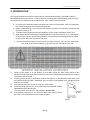
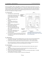
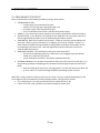
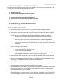
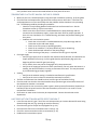
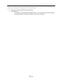
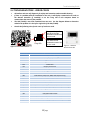
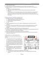
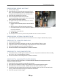
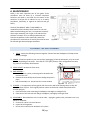
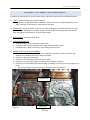
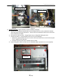
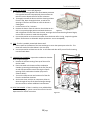
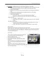
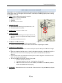
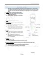
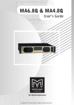
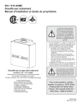
Troubleshooting Guide 910 / 910 ASME (T‐M50 / T‐M50 ASME) On‐Demand Water Heater Troubleshooting Guide 910 / 910 ASME (T‐M50 / T‐M50 ASME) A.O. Smith Water Products Company 500 Tennessee Waltz Parkway Ashland City, TN 37015 Toll Free: 1‐877‐737‐2840 9/12/11 1|Page 321925‐000 Troubleshooting Guide Table of Contents Troubleshooting Guide 1. SPECIFICATIONS.……………………………………………………………………………..……………………3 2. INTRODUCTION.…………………………………………………………………………………..………………4 3. NORMAL OPERATION…………….………………………………………………………………………..…..5 Activation………………………………………………………………………………………………….5 Operation.………………………………………………………………………………………………..5 Shutdown……….………….………………………………………………………………………..…..5 4. INSTALLATION….…………………………………………………………………………….…………………….6 Venting…………….………………………………………………………………………………..…..…6 Gas Line…………….………………………………………………………………………………………6 Water Line………………… ………………………………………………………………………..…..6 Power Supply..…………………………………………………………………………………………..6 5. TROUBLESHOOTING.....…………………………………………………………………………………………7 Preliminary Checklist.………………………………………………………………………..…..…7 General Problems..……………………………………………………………………………………8 Error Codes.………………………….……………………………………………………………..…. 12 Procedures.……..……………………………………………………………………………………….20 Verifying proper Dipswitch settings.....……………………………………….…20 Draining the unit….………………………………………………………………………..22 Cleaning the filter…………………………………………….……………………………22 Checking for a Cross Connection…………………………………………….……..22 Check for Reverse Connection…………………………………………….…………22 Check gas supply pressure…………………………………………….……………….23 Purge the gas line of air…………………………………………….…………………..23 Adjusting manifold pressure…………………………………………….…………...24 Resetting the computer board…………………………………………….………..24 Checking the OHCF……………………………….……………………………………….25 6. MAINTENANCE….…..…………………………………………………………………………….………….……26 Rod Assembly..…………………………………………………………………………………..…..…26 Burner & Rod Assembly…..………………………………………………………………………..27 Heat Exchanger…..….…………….……………………………………………………………..…..31 Flow Sensor….….………………………………………………………………………………………..36 Descaling the Unit……………………………………………………………………………………..37 ... 2|Page Troubleshooting Guide 1. Table 1 ‐ SPECIFICATIONS Unit Model 910 / 910 ASME (T‐M50 / T‐M50 ASME) Unit dimensions H25.3"×W24.8"×D11.8" Weight 102 lbs. Combustion INPUT BTU/h Water control Operation 380,000 Min 15,000 Combustion System Power vent Installation Indoor, Outdoor, Direct vent Fan motor PWM Turbo fan Manifold Pressure* Features Max LP 3.7” WC Natural 2.7”WC LP 0.9” WC Natural 0.7” WC Max Min Flow rate 0.5 to 14.5 GPM Available set temp. 100°F to 185°F default set 120°F Temperature dipswitch setting Bypass valve 100°F, 115°F, 120°F, 135°F, 145°F, 155°F, 165°F, 185°F Yes Thermistors 3 thermistors (In, Out, Mixing) Available remote controller TM‐RE30 PCB Model Central board: MC50 (Part # EM306) / Right and left computer board:910 (T‐M50) (Part # EM307) Indicators Red LED on PCB during operation & 7‐Seg LED Power supply control GFI (Excluding surge absorber) Freeze protection Ceramic heaters, Auto‐FM system and Auto‐firing system Self‐combustion improvement Air Fuel Ratio detection system Easy‐link system Yes Multi‐unit system Yes *The manifold pressure measurement is base on conditions without front cover. 3|Page Troubleshooting Guide 2. INTRODUCTION This manual provides the necessary information for troubleshooting the 910 / 910 ASME (T‐M50 / T‐ M50 ASME) tankless water heaters. It will be effective in helping your troubleshooting needs as long as the instructions are followed in the intended order. Here is how to use this manual: • First refer to the Installation Manual as the primary source of information. Refer to it along side this manual throughout the troubleshooting process. • Before troubleshooting, if you are unfamiliar with how a tankless unit operates, read the Normal Operation section (p. 5). • To double‐check/troubleshoot a new installation, use the Proper Installation section (p. 6). • When beginning troubleshooting, first go through the Preliminary Checklist (p. 7); it is designed to fix the most common and frequent problems, and provide you with background information to help narrow down the information you need. • After the Preliminary Checklist, move to the Error Codes section (p. 12) if you have received an error code, or to General Problems (p. 8) if you have not received an error code. IMPORTANT • • WARNING Installation and service must be performed by a qualified installer (for example, a licensed plumber or gas fitter). Otherwise the warranty will be void. The installer/service agent (licensed professional) is responsible for correctly installing or servicing your water heater and for compliance with all national, state/provincial, and local codes. *For all units installed in the state of Massachusetts, it is required that the installer either be a licensed plumber or licensed gas fitter. GENERAL INSTALLATION GUIDELINES 1. 2. 3. 4. 5. Follow all local codes, or in the absence of local codes, follow the most recent edition of the National Fuel Gas Code: ANSI Z223.1/NFPA 54 in the USA or CAN/CSA B149.1 Natural Gas, Propane Installation Code in Canada. Properly ground the unit in accordance with all local codes or in the absence of local codes, with the National Electrical Codes: ANSI/NFPA 70 in the USA or CSA standard C22.1 Canada Electrical Code Part 1 in Canada. Carefully plan where you intend to install your water heater. Check the rating plate for the correct GAS TYPE, GAS PRESSURE, WATER PRESSURE and ELECTRIC RATING. *If this unit does not match your requirements, do not install. RATING If any problem should occur, turn off all hot water taps and turn off the PLATE gas. Then call a trained technician or the gas company. Figure 1 4|Page Troubleshooting Guide 3. NORMAL OPERATION The 910 / 910 ASME (T‐M50 / T‐M50 ASME) is a combination of two tankless water heaters in one case, as pictured below. When troubleshooting this unit, it is important to identify which major assembly, left or right, is the side that the problem is located. Once it is determined which side contains the problem, unless specifically stated, the procedures for troubleshooting and maintenance are exactly the same for both the left and right heat exchanger assemblies. 1) ACTIVATION a. A hot water tap is opened enough that the flow sensor detects a flow rate through the heater greater than the activation point of 0.5 gpm. b. The fan activates after flow is detected. c. The computer checks for any problems with the unit before startup. d. Igniter activates. You can hear the buzzing of the spark igniter. e. Main gas valve, proportional valve, and solenoid gas valves will open. You will hear a deep “clunk clunk” noise. f. Once a flame is detected, the red LED located on the computer Figure 2 board will activate. g. In a multi‐heater setup, the controller will activate the next heater in 2‐4 gpm increments, depending on the set temperature. *This diagram illustrates the tankless water heater design concepts only and is not accurate to the units description. 2) OPERATION a. The proportional gas valves will modulate based on the amount of hot water demanded and the temperature rise needed. The fan speed will modulate as well to create an efficient burn. b. You will notice that only partial sections of the burners will be lit. This is normal operation; there are three sections on the burner assemblies, and the computer controls the amount of sections needed based on the flow rate and temperature rise required. 3) SHUTDOWN a. The heater will shut down when the water flow rate drops below the deactivation point of 0.4 gpm. b. The heater will close the main gas valve and solenoid gas valves, extinguishing the flame. c. When the flame disappears the red LED will turn off. d. The fan will increase in speed to purge the venting of any remaining exhaust gases. The length of post‐purge can last up to 1 ½ minutes. e. The heater goes into standby waiting for the process to begin again. 5|Page Troubleshooting Guide 4. INSTALLATION 1. Follow all local codes, or in the absence of local codes, follow the most recent edition of the National Fuel Gas Code: ANSI Z223.1/NFPA 54 in the USA or CAN/CSA B149.1 Natural Gas, Propane Installation Code in Canada. 2. All gas water heaters require careful and correct installation to ensure safe and efficient operation. This manual must be followed exactly. Read the “Safety Guidelines” section in the installation manual. 3. The manifold gas pressure is preset at the factory. It is computer controlled and should not need adjustment. 4. Maintain proper space for servicing. Install the unit so that it can be connected or removed easily. Refer to the Clearances Section on p. 8 of the installation manual for proper clearances. 5. The water heater must be installed in a location where the proper amount of combustible air will be available to it at all times without obstructions. 6. The electrical connection requires a means of disconnection, to terminate power to the water heater for servicing and safety purposes. 7. Do not install the unit where the exhaust vent is pointing into any opening in a building or where the noise may disturb your neighbors. Make sure the vent termination meets the required distance by local code from any doorway or opening to prevent exhaust from entering a building. 8. Particles from flour, aerosols, and other contaminants may clog the air vent or reduce the functions of the rotating fan and cause improper burning of the gas. Regularly ensure that the area around the unit is dust‐ or debris‐free; regular maintenance is recommended for these types of environment. 9. If you will be installing the water heater in a contaminated area with a high level of dust, sand, flour, aerosols or other contaminants/chemicals, they can become airborne and enter and build up within the fan and burner causing damage to the water heater. 10. Direct‐vent conversion: • These units may be converted to a direct‐vent (sealed combustion) appliance by installing a direct‐vent conversion kit (Part No. 9007669005) which will bring in all required combustible air from outside the building. When installing the conversion kit, please follow all instructions included with the kit. • If the water heater is used as a direct‐vent appliance, the unit requires a 5” intake air pipe. The intake pipe must be sealed airtight. Air supply pipe can be made of ABS, PVC, galvanized steel, corrugated aluminum, corrugated stainless steel or Category III stainless steel. • Terminating the venting through a sidewall is recommended for the direct‐vent system. • Running the exhaust vent and the intake pipe parallel is recommended. • Terminating the exhaust and intake on the same wall / surface is recommended. Terminating in the same pressure zone allows for pressure balancing, which prevents nuisance shutdowns. Be sure to allow for proper clearance between the exhaust and intake. 6|Page Troubleshooting Guide 5. TROUBLESHOOTING 5.1 PRELIMINARY CHECKLIST Check all of these basic items before proceeding onto any other section: • GAS/WATER/ELECTRIC: o The gas supply valve should be fully open. o Verify the correct gas type is being used, NG or LP. o The water supply valve should be fully open. o The unit should be connected to a 120 VAC 60 Hz power supply. • REMOTE: If you are using a remote controller, the remote’s power button must be turned on. • HIGH ALTITUDE: Is your location at an altitude of over 3000 feet? This may cause a lack of air. See the high altitude procedure in the Troubleshooting Procedures section. • HARD WATER: What is the hardness of the water? A softener is always recommended, but if the water is above 7 grains of hardness or 70‐140ppm, one must be installed. If there is no water softener installed, existing installations will gradually accumulate scale buildup on the heat exchanger and cause a leak. Heat exchanger failures do to hard water scale are not covered under the warranty. • NEW INSTALLATIONS: Is this installation a few years old or brand new? o A unit that has worked properly for a while but is now struggling may have become scaled up or contains a dirty burner. o A new installation most likely is installed or plumbed incorrectly. • EXTERNAL PROBLEM: Test whether the problem is within the unit or external to the unit (i.e. in the plumbing system) by attempting to run hot water locally through the pressure relief valve (PRV). o Does the heater ignite and remain running properly? Or does the heater shut down into an error code? If it runs fine through the PRV the plumbing system is at fault. NEXT STEP: Finally, check to see if the unit has an error code. The error code will be displayed on the seven segment LED on the bottom left of the computer board. See figure 4 for location. • If it is displaying an error code, proceed to the Error Codes section (p. 12). • If there is no error code, proceed to the General Problems section (p. 8). 7|Page Troubleshooting Guide 5.2 TROUBLESHOOTING ‐ GENERAL PROBLEMS Proceed to the Error Codes section if an error code is identified. For other common problems that do not involve an error code, see if the following items help: The water is not hot enough. The water is too hot. Temperature fluctuates when a fixture is opened. Unit does not ignite when water goes through it. It takes a long time to get hot water at the fixtures. The fan motor is still spinning after operation has stopped. Abnormal sounds come from the unit. Loss of pressure at all sinks when the dishwasher fills. Unit has power, gas, and water but does not turn on. Multiple Heater Setup THE WATER IS NOT HOT ENOUGH • • • • • • The set temperature may be set too low. The temperature can be changed with the pushbuttons on the PCB or by the remote temperature controller, if one is installed. Check the flow and temperature right at the unit at the pressure relief valve with a handheld thermometer. If the flow rate and temperature are correct at the PRV, then the problem resides elsewhere in the plumbing line. The following could be plumbing line problems: o Check for cross plumbing between cold water lines and hot water lines. See the Procedures section (p. 22) for instructions. o Check to see that a check valve is installed between the pump discharge and the connection to the cold water supply. Inspect the check valve for proper operation. If there isn’t one installed, or if it is malfunctioning, cold water may be back‐feeding into the system. Unit may be hard water scaled. The scale acts as an insulator preventing the heat exchanger from transferring heat to the water. The unit may not be receiving enough gas. o The gas supply valve may not be fully open. o The gas line may be sized improperly. o The gas supply pressure may be too low. This may be caused by a malfunctioning gas supply regulator, so check to see if your regulator is working properly. Double‐check for a 101 error code. A 101 error code will reduce the amount of gas input into the heater. Output temperature will be affected if air flow is impeded. This could include blockage in the venting line, or a clogged/dirty burner from contaminated intake air. THE WATER IS TOO HOT • • • The set temperature may be set too high. The temperature can be changed with dipswitches on the PCB or by the remote temperature controller, if one is installed. The flow adjustment valve could be obstructed due to hard water scale or debris, causing lower than expected water flow. Verify water flow with a graduated container or with the remote temperature controller, if one is installed. The output thermistor could be compromised. This component may be checked by entering the Diagnostics Mode on a remote controller, if one is installed. Turn power off to the unit and run cold water through it; check to see if the inlet and outlet temperatures read the same on the 8|Page Troubleshooting Guide remote. For instructions on how to do this, refer to the Maintenance Sheet, packaged with every tankless water heater and located behind the front panel of the unit. TEMPERATURE FLUCTUATES WHEN A FIXTURE IS OPENED • • • • • • • • Make sure the unit is installed properly using the Proper Installation section (p. 6) of this guide. Check the flow and temperature right at the unit at the pressure relief valve. If the flow rate and temperature are correct at the PRV, then the problem resides elsewhere in the plumbing line. The following could be plumbing line problems: o Check for cross plumbing between cold water lines and hot water lines. See the Procedures section (p. 22) for instructions. o Check to see that a check valve is installed between the pump discharge and the connection to the cold water supply. Inspect the check valve for proper operation. If there isn’t one installed, or if it is malfunctioning, cold water may be back‐feeding into the system. o Problems with a recirculation system: Check that a check valve is installed between the pump discharge and the connection to the cold water supply. Check to see if the pump is operating properly. Check for air cavitation. The pump will be very hot or chattering. Check the directional indicator on the pump flange. Check the sizing of the pump – a minimum flow of 2 gpm is required. Check gas supply o Verify the gas supply lines are sized for the maximum Btu/h demand, as indicated in the Proper Installation section (p. 6) of this guide (See the specification page p.3 at the beginning of this manual for gas input rating). o For LP models, there may not be enough gas left in the propane tank. o Verify that the supply gas pressure is within specification, not only when the heater is in standby, but while the heater is running on maximum fire as well. This may be caused by a malfunctioning gas supply regulator. Venting o Verify that the exhaust venting is installed to manufacturer’s specification. o Verify that the vent run does not exceed the maximum limit (50 ft.) The filter on cold water inlet should be clean; look for signs of hard water scaling. Check to make sure that the clear tube between the proportional gas valve and the bottom of the combustion chamber is connected. On well systems or even on some city water systems, water pressure fluctuations (especially on low flow) of 8 to 10 psi will result in flow rate fluctuations, which will in turn result in minor temperature fluctuations. Flow sensor or water control valve may be compromised. Contact the technical service department. UNIT DOES NOT IGNITE WHEN WATER GOES THROUGH IT • • • • • Is the flow rate over 0.5 gpm? See if the unit initiates when you increase demand of water being drawn through the unit (e.g. opening up more hot fixtures). Check that the gas line is open and is purged of air (p. 23). Check that the filter on the cold water inlet is clean (p. 22). Check for reverse connection and cross connection (p. 22). Problems with recirculation system 9|Page Troubleshooting Guide See that a check valve is installed between the pump discharge and the connection to the cold water supply. A malfunctioning or missing check valve will cause cold water to back‐feed into the system. If you use the remote controller, is the remote power button turned on? Check to see if the Computer board is receiving power. This can be verified by observing the computer board red LED. o If it is not lit, the computer board is not being powered. Check to see if the ON/OFF switch below the fuse box is set to the on position, or if the fuse in the fuse box is blown. If the fan does not initiate at all and it is verified that the unit is powered (see above), the flow sensor may not be working properly. Check the flow sensor for proper impeller functionality. o • • • IT TAKES A LONG TIME TO GET HOT WATER AT THE FIXTURES • • The time it takes to deliver hot water to your fixtures depends on the length of piping between the two. The longer the distance or the bigger the pipes, the longer it will take to get hot water. If this is the case and you would like to receive hot water to your fixtures quicker, you may want to consider a hot water recirculation system. Problems with the recirculation system. o See that a check valve is installed between the pump discharge and the connection to the cold water supply. A malfunctioning or missing check valve will cause cold water to back‐feed into the system. THE FAN MOTOR IS STILL SPINNING AFTER OPERATION HAS STOPPED • This is normal. After operation has stopped, the fan motor keeps running from 5 to 50 seconds in order to re‐ignite quickly, as well as purge all the exhaust gas out of the flue. ABNORMAL SOUNDS COME FROM THE UNIT • • Check the fan for debris. Contact the technical service department. Figure 3 LOSS OF PRESSURE AT ALL SINKS DURING COMMERCIAL DISHWASHER FILLS • • • • Verify the capacity of the heater(s) versus the GPM demand of the dishwasher. Check the size of the supply lines to the dishwasher. Look for a water regulator on the dishwasher. Check the dishwasher rating plate to confirm the recommended supply water pressure. Unit may be hard water scaled. Scale can reduce pressure and flow of water through the unit; this can occur as quickly as a few months. UNIT HAS POWER, GAS, AND WATER BUT DOES NOT TURN ON • • • For new unit installs, check to make sure the unit is not plumbed in backwards. o Shut off cold water feed only. o Open nearest hot water tap. Water flow should stop. If not there is a cold water cross connection. o Open Pressure Relief Valve. Water flow should stop. If not unit is plumbed in backwards. Clean the filter (p. 22). If the fan never initiates, check for a fouled water flow sensor (p. 36). 10|Page Troubleshooting Guide EASY‐LINK SYSTEM SETUP (MULTIPLE HEATER SETUP) • • Refer to the Installation Manual for proper setup. Unit Numbering o The master unit will always be assigned number 1. The remaining units will be randomly assigned numbers 2‐4 (if there are 4 units in the Easy‐Link system). 11|Page Troubleshooting Guide 5.3 TROUBLESHOOTING ‐ ERROR CODES • • • All tankless units are self diagnostic for safety and convenience when trouble shooting. If there is a problem with the installation or the unit, it will display a numerical error code on the Remote Controller (if installed), or on the 7‐Seg LED on the computer board to communicate the source of the problem. The 910 (T‐M50) is two units combined into one case. See the diagram below to determine whether the problem is in the left or right side of the 910 (T‐M50). Consult the following chart for the cause of each error code. • Figure 4 – Error Code Location The top red lamp will flash when the right combustion section has an error code. The mid red lamp will flash when the left combustion section has an error code. 7-Seg LED Table 2 – Error Codes Error Code 031 101 111 121 311 321 331 391 441 510 551 611 631 651 661 681 701 721 741 761 991 Figure 5 – TM‐RE30 Remote Controller Malfunction Description Incorrect Dipswitch Settings Warning for 991 Error Code Ignition Failure Flame Loss Output Thermistor Inlet Thermistor Mixing Thermistor Air‐fuel Ratio Rod Failure Flow Sensor (Easy‐Link, Multi‐Unit System only) Abnormal Main Gas Valve Abnormal Solenoid Gas Valve Abnormal Fan Motor Pump Failure Flow Adjustment Valve ( Easy‐Link, Multi‐Unit System only) Bypass Valve Fault External Fan Motor Failure Computer Board Fault False Flame Detection Remote Controller Communication Failure Communication Failure (Easy‐Link, Multi‐Unit System only) Abnormal combustion 12|Page Troubleshooting Guide ERROR CODE 031: INCORRECT DIPSWITCH SETTINGS 1) Turn off the power supply. 2) Remove front cover and locate the dipswitches on the center of the computer board. 3) Check the dipswitch settings on the left and right banks. Refer to p.20 for the correct dipswitch positions. a. Gas type is a common dipswitch error. b. Most other switches should be on default setting UNLESS the particular setup requires otherwise. c. Easy‐Link systems: The master heater shall have the number 10 dipswitch on the right bank in the ON position (left). The remaining heaters (the slave heaters) will have the number 10 dipswitch in the OFF position (right) and the communication wires will be attached to the slave in/out plugs. ERROR CODE 101: ABNORMAL COMBUSTION 1) Blockage in the airway. Check the following areas: a. Venting length obstruction (Birds’ nests, trash, etc.) b. Backflow preventer installed backwards c. Heat exchanger d. Fan 2) Check the manifold pressure (p. 23‐24). Adjust the manifold pressure to the correct values if necessary. 3) If intake air is contaminated with dust, lint (laundry machine nearby), grease (kitchens), or other contaminants, clean the burner. See p. 26 on procedures for cleaning the burner & sensor assembly. 4) Weather related issues: high winds, frozen vent termination flap, etc. 5) Installations at altitudes around or over 3000 feet: Change dipswitches on the computer board for FM+ modes. See dipswitch explanations on page 20. 6) Make sure all dipswitches are set properly for the type of installation. 7) If the cause of the 101 error code has been determined and solved, reset the computer board to clear the error code (p. 24). ERROR CODE 111: IGNITION FAILURE Heater does not fire after three failed attempts at Hi‐Limit Switches ignition. 1) Verify that the hi‐limit switch is not tripped. Turn the power off to the unit. Push the white button in. The switch will reset when you hear and feel the button click. Turn the power back on and test the heater. If the unit fires on, the cause of the hi‐ limit trip must be determined. Please contact the technical service department for further technical support. 2) Check the gas supply. Verify that sufficient gas is being supplied to the heater and the gas line is clear of debris or any air. Purge the line of air if needed (p. 23). Figure 6 a. It is possible there is a faulty pressure regulator at the gas meter. b. For propane units, colder periods of the day result in a cold regulator and may cause this problem. 13|Page Troubleshooting Guide 3) Verify that the gas supply pressure is within specifications when the heater is in standby and when the heater is running. 4) Check that the clear plastic tube connecting the proportional gas valve to the combustion chamber is attached. 5) The overheat cutoff fuse (OHCF) may have been compromised. For procedures on how to check whether the OHCF is intact, refer to p. 25. If the OHCF has been compromised, contact the technical service department for further assistance. 6) If flame comes on for only 1‐2 seconds before going out, clean the flame sensor (p. 26). 7) Check the igniter for a spark. The spark may be viewed through the sight glass located next to the igniter and flame sensor. a. A strong blue spark will remain steady and in place, while a weak spark will jump around. b. If no spark or a weak spark is observed, check the igniter wire connections and make sure these are secure. If these are secure, a replacement igniter will be required. 8) Check for blockages in the venting, such as bird nests, animals, or trash. a. PC Board fault or Gas Solenoid fault. Contact the technical service department. ERROR CODE 121: FLAME LOSS This error code appears if the flames disappear while the unit is still supposed to be in operation. 1) Verify that the hi‐limit switch is not tripped. Turn the power off to the unit. Push the white button in. The switch will reset when you hear and feel the button click. Turn the power back on and test the heater. If the unit fires on, the cause of the hi‐limit trip must be determined. Please contact the technical service department for further technical support. 2) Check the gas supply. Verify that sufficient gas is being supplied to the heater and the gas line is cleared of debris. a. It is possible there is a faulty pressure regulator at the gas meter. b. For propane units, colder periods of the day result in a cold regulator and may cause this problem. 3) Verify that the gas supply pressure is within specifications when the heater is in standby and when the heater is running. 4) Check that the clear plastic tube connecting the proportional gas valve to the combustion chamber is attached. 5) If the flame comes on for 1‐2 seconds but then goes Clear pressure hose out, clean the flame sensor (p. 27). connection 6) The overheat cutoff fuse may have been compromised. For procedures on how to check whether the OHCF is intact, refer to p. 25. If it has, contact the technical service department for further assistance. 7) Check for blockages in venting, such as bird nests, animals, or trash. 8) PC Board fault or Gas Solenoid fault. a. If one of these is suspected to be the problem, contact the technical service department. Figure 7 14|Page Troubleshooting Guide ERROR CODE 311: OUTPUT THERMISTOR 1) Check that the wire connections are secure and free of burns or cuts. The output thermistor is located on the heat exchanger on the right side. 2) Check the resistance value; it should be about 9.0kΩ at room temperature (about 74°F). 3) Clean the thermistor. a. Drain the unit of water. See p. 22. b. Remove the fastener holding the output thermistor and pull out the sensor probe. Clean the probe to a silver finish. Do not lose the rubber o‐ring that wraps around this sensor. c. Replace and test. 4) If the error code persists, replace the thermistor. Output Thermistors Figure 8 ERROR CODE 321: INLET THERMISTOR 1) Check that the wire connections are secure and free of burns or cuts. The inlet thermistor is embedded in the water inlet connection. 2) Check the resistance value; it should be about 9.0kΩ at room temperature (about 74°F). 3) Clean the thermistor. a. Drain the unit of water. See p. 22. b. Remove the computer board to access the inlet thermistor. The computer is fixed in place by a single screw at the top of the board. c. Remove the screw, pull out the sensor probe. Clean the probe to a silver finish. Do not lose the rubber o‐ring that wraps around this sensor. d. Replace and test. 4) If the error code persists, replace the thermistor. Mixing Thermistor Inlet Thermistor Mixing Thermistor Figure 9 ERROR CODE 331: MIXING THERMISTOR 1) Check that the wire connections are secure and free of burns or cuts. The mixing thermistor is embedded in the water outlet connection. 2) Check the resistance value; it should be about 9.0kΩ at room temperature (about 74°F). 3) Clean the thermistor. a. Drain the unit of water. See p. 22. b. Remove the computer board to access the mixing thermistor. The computer is fixed in place by a single screw at the top of the board. c. Remove the screw, pull out the sensor probe. Clean the probe to a silver finish. Do not lose the red rubber o‐ring that wraps around this sensor. d. Replace and test. 4) If the error code persists, replace the thermistor. 15|Page Troubleshooting Guide ERROR CODE 391: AIR‐FUEL RATIO ROD FAILURE 1) Check that the wire connections are secure and free of burns or cuts. 2) Check that the clear plastic tube connecting the proportional gas valve to the combustion chamber is attached. 3) Clean the AFR (p. 26). ERROR CODE 441: FLOW SENSOR Figure 10 Part of an Easy‐Link or Multi‐Unit system, the master unit signaled for an additional heater to activate and it did not. 1) Verify that water is being supplied to the heater in error. 2) Verify that the wires are connected to the computer board. 3) Check the inlet filter for any debris. See p. 22. 4) Check the flow sensor for debris. ERROR CODE 510: ABNORMAL MAIN GAS VALVE Figure 11 Driving circuit fault for the main gas valves. 1) If the hot water is shut off, but flames are still visible through the sight glass, immediately shut off gas and power to the unit and contact the technical service department. 2) Check the wire connections to the gas valve assembly for burns or cuts. 3) If the unit was recently rebuilt, make sure that each gas valve wire is plugged into the proper place. 4) Verify that the supply gas pressure is within the specified limits. Too high of an inlet gas pressure may cause the main gas valve to jam or could be damaged. ERROR CODE 551: ABNORMAL SOLENOID GAS VALVES Driving circuit fault for the solenoid gas valves. 1) If the hot water is shut off, but flames are still visible through the sight glass, immediately shut off gas and power to the unit and contact the technical service department. 2) Check the wire connections to the gas valve assembly for burns or cuts. 3) If the unit was recently rebuilt, make sure that each gas valve wire is plugged into the proper place. 4) Verify that the supply gas pressure is within the specified limits. Too high of an inlet gas pressure may cause the main gas valve to jam or could be damaged. 16|Page Solenoid Gas Valves Proportional Gas Valve Main Gas Valve Figure 12 Troubleshooting Guide ERROR CODE 611: ABNORMAL FAN MOTOR 1) Turn off power supply. 2) Check fan motor wiring for any breakages, burn marks on the PC board, or moisture. If moisture is found, allow connection to completely dry before turning power back on. 3) Check fan housing for water. If found, please dry the fan, then test heater. 4) To remove the fan motor. a. Turn off the power supply. b. Move the computer board out of the way. c. Locate the two Phillips head screws fitted at the front of the fan motor to the combustion chamber box. Figure 13 d. Slide the fan out towards the left. e. If signs of water are evident, water may have damaged the fan motor requiring replacement. 5) If the 611 error code still appears after all items have been checked, the PCB may need replacement. Contact the technical service department. ERROR CODE 631: PUMP FAILURE 1) Check to see whether the pump connected to the PCB works properly ERROR CODE 651: ABNORMAL FLOW ADJUSTMENT VALVE 1) Turn off power supply. 2) Check that all wire connections are secure and free of burns. The flow adjustment valve is located behind the computer board and attached to the cold water inlet. 3) Check for water leakage from the valve. 4) Do a visual inspection of the PCB. Check for connection/breakage of wires and/or burn marks on the board. PCB may need to be replaced. 5) The flow adjustment valve may need to be cleaned. To remove, follow the steps below: a. Remove the four waterway clips on each side of the valves. Figure 14 b. Slide the valve up off the inlet water connection. c. Check both ends of the valve for sediment or debris. Use a brush or descaling solution to remove the sediment. d. Re‐install the valve and clips. e. Test the heater. 6) The flow adjustment valve may need to be replaced if the valve cannot be cleaned. Contact the technical service department. 17|Page Troubleshooting Guide ERROR CODE 661: BYPASS VALVE FAULT 1) Turn off power supply. 2) Check that all wire connections are secure and free of burns. The flow adjustment valve is located behind the computer board and attached to the cold water inlet. 3) Check for water leakage from the valve. 4) Do a visual inspection of the PCB. Check for connection/breakage of wires and/or burn marks on the board. PCB may need to be replaced. 5) The bypass valve may need to be cleaned. To remove, follow the steps below: a. Remove the four waterway clips on each side of the valves. b. Slide the valve up off the inlet water connection. Figure 15 c. Check both ends of the valve for sediment or debris. Use a brush or descaling solution to remove the sediment. d. Re‐install the valve and clips. e. Test the heater. 6) The flow adjustment valve may need to be replaced if the valve cannot be cleaned. ERROR CODE 681: EXTERNAL FAN MODE FAILURE 1) Check whether the external fan motor connected to the central computer board works properly. ERROR CODE 701: COMPUTER BOARD FAULT 2) 3) 4) 5) 6) Turn off the power supply. Check all wire connections and make sure they are secure and free of burns or cuts. Inspect the PCB for connection/breakage of wires and/or burn marks on the board. Verify that supply gas pressure is within specifications. Contact the technical service department for further assistance. ERROR CODE 721: FALSE FLAME DETECTION 1) First and foremost, shut off all gas and power to the unit. The problem could be the flame assembly, but if it isn’t, this is a very dangerous situation. 2) Contact the technical service department for further assistance. ERROR CODE 741: MAIN REMOTE CONTROL PROBLEM This error code only occurs when there is a miscommunication between the temperature remote controller and the water heater. 1) Check that all wiring is properly connected to the remote. 2) Verify the correct model of remote is being used for the corresponding tankless model. 3) Verify that only a remote is installed. Multiple remotes will result in this error code. 4) If you disconnect the remote from the heater with the power supply on, this error code will result. Turn off power before disconnecting the remote from the heater. 5) Check for any signs of power surges. 18|Page Troubleshooting Guide ERROR CODE 761: COMMUNICATION FAILURE 1) This error code only occurs in a multiple heater setup, where there is a miscommunication between master and slave units for Easy‐Link systems. 2) This error code will only be displayed on the master heater. 3) This error indicates that the master unit has lost communication with the indicated heater. 4) Verify that there is power to the unit that has lost communication. 5) See the Installation Manual for proper communication cable setup. 6) Check for signs of power surges. ERROR CODE 991: ABNORMAL COMBUSTION 1) Refer to error code 101. 2) Contact the technical service department for further assistance if nothing has worked so far. The manifold gas pressure may need adjustment. 3) If you are sure that the problem has been solved, reset the computer (p. 24). 19|Page Troubleshooting Guide 5.4 TROUBLESHOOTING ‐ PROCEDURES Verifying proper Dipswitch settings… p.20 Draining the unit………………………………p.22 Cleaning the filter…………………………….p.22 Checking for a Cross Connection………p.22 Check for Reverse Connection………….p.22 Check gas supply pressure………………. p.23 Purge the gas line of air………………….. p.23 Adjusting manifold pressure…………….p.24 Resetting the computer board………… p.24 Checking the OHCF…………………………. p.25 VERIFYING PROPER DIPSWITCH SETTINGS: • Incorrect Dipswitch settings can cause a 031 error code, or a number of operational problems. Figure 17 Figure 16 Table 3 – Dipswitches, Left/Right Computer Board No. Function 1 Fan Motor + (Increases fan motor speed automatically) 2 N/A 3 N/A 4 Allow adjustments of fan motor speed (Similar to changing manifold pressure) 5 Allow access to operation history (For specialized purposes only, do not use) 6 Activation of the fan motor freeze protection system 7 N/A 8 Fan Motor ++ (Increases fan motor speed automatically) ON position +6% FM‐speed OFF position Disable (Default) N/A N/A Enable EEPROM data transfer Disable N/A (Default) N/A (Default) Disable (Default) N/A +12% FM‐speed N/A (Default) Disable (Default) 20|Page Disable (Default) Enable (Default) Troubleshooting Guide Figure 19 Figure 18 Table 4 – Dipswitches, Center Board, UPPER No. Function 1 Gas Type 2 N/A 3 N/A 4 Pump Mode 5 6 7 Activation of the Freeze Protection Pump for recirculation systems Number of priority combustion units Table 5.4 – Dipswitches, Center Board, LOWER No. Function 1 Temperature setting (Default 120°F) 2 3 ON position Propane N/A N/A OFF position Natural Gas N/A N/A Enable Disable (Default) One priority unit Two priority units ON position 21|Page OFF position Troubleshooting Guide 4 5 Activation of Individual Operation mode Direct vent setting 6 Outdoor setting 7 Activation of checking the recirculation pump Enable (Default) Enable Direct vent mode Enable Outdoor Mode Enable 8 Parent/Child setting on Easy‐Link systems Parent Disable Disable (Default) Disable (Default) Disable (Default) Child (Default) DRAINING THE UNIT: 1) 2) 3) 4) 5) Close the manual gas shut off valve. Turn off power to the unit, and then turn on again. Wait 30 seconds, and then turn off power to the unit, yet again. Close the cold water inlet shutoff valve. Open all hot water taps in the house, or open the pressure‐relief valve to remove the initial pressure. When the residual water flow has ceased, close all hot water taps. 6) Unscrew the drain plugs (hot water outlet drain plug and cold water inlet filter) to drain the remaining water out of the unit. Have a bucket or pan to catch the water from the unit’s drain plugs. Wait a few minutes to ensure all water has completely drained from unit. CLEANING THE FILTER: 1) Drain the unit (procedure above). 2) Check the water filter located within the cold inlet. With a tiny brush, clean the water filter of any debris which may have accumulated and reinsert the filter back into the cold water inlet. 3) Securely screw the filter back into place. Hand‐tighten only. Figure 20 CHECKING FOR A CROSS CONNECTION: 1) 2) Turn off cold water supply. Turn on all hot water fixtures. a. The water should eventually completely drain. b. If water continues to run, the fixtures and plumbing system needs to be checked. c. Cold water cross connections may be related to a recirculation pump application, a bad check valve, or missing check valve in the application. CHECK FOR REVERSE CONNECTION: 1) 2) 3) Close cold water supply at the inlet. Open the pressure‐relief valve; it should be installed on the hot side outlet of the unit. If water continues to run through the pressure‐relief valve, the system has a reverse connection. 22|Page Troubleshooting Guide CHECK GAS SUPPLY PRESSURE: 1) Close the manual gas inlet shut off valve on the gas supply line. 2) Open a faucet. The unit should turn on and the gas in the pipe line should purge. Leave the faucet on to keep the unit running until it shuts down due to lack of gas, and then shut the faucet off. Ignore any error codes that may occur at this time. 3) Remove the screw for the pressure port located on the gas inlet shown on the right. 4) Connect a manometer to the pressure port. 5) Slowly re‐open the manual gas valve. Check to Figure 21 see that there are no gas leaks. 6) Open some of the fixtures that use the highest flow rate to activate. 7) Check the inlet gas pressure. Appropriate pressures are listed in the specification page in the installation manual. PURGE THE GAS LINE OF AIR: 1) 2) 3) 4) The unit should not be running during this procedure. Turn off power to the unit. Turn the gas valve to the off position (perpendicular to the gas line). Loosen the gas line on the unit side of the gas valve (at a flare fitting or union). Next open the gas valve very slightly until you can smell gas by wafting the air towards your nose. This means any air previously in the gas line has been removed and only gas remains. 5) Turn gas back off and re‐tighten gas line. 6) Turn gas back on and check for leaks. Spray water & dish soap mixture onto fittings. No bubbles means there are no leaks. CHECKING MANIFOLD GAS PRESSURE: 1) Ensure the unit is not in operation. 2) Remove the screw off the manifold port. 3) Connect a manometer to the manifold port using a tube. Ensure that this connection is secure enough to prevent gas leak. 4) Run water through the unit to activate its operation. It is suggested that a large amount of flow is drawn in order to prevent overheating during max burn. If presence of a gas leak is detected, immediately shut off the unit and Figure 22 inspect the tube/manifold connection; otherwise, proceed onto the next step. 5) To check the manifold gas pressure during maximum combustion, press and hold the “MAX” button on the computer board. To check the manifold pressure during minimum combustion, press and hold the “MIN” button on the computer board. The desired pressures are listed in the specification table at the beginning of this manual. 6) If the manifold pressures do not match up with those listed, adjust the manifold pressure (see the following procedure). 23|Page Troubleshooting Guide ADJUSTING MANIFOLD PRESSURE: The manifold gas pressure of the tankless unit can be adjusted by the following procedure. Adjusting the manifold pressure can cause unexpected combustion conditions during operation, which can cause a health hazard, damage the tankless unit, and or shorten its lifespan. Therefore, changing the manifold pressure is not recommended unless there are very strong reasons to do so (e.g. high elevation installations), and with the consultation of the technical service department. WARNING 1) Set up the manometer by following steps 1 through 4 on the “Checking manifold gas pressure” procedures on p. 21. 2) Press and hold down the “MIN” button on the computer board. While holding down the “MIN” button, press either the “INCREASE” or “DECREASE” button to increase or decrease the manifold gas pressure, respectively (Figure 2). Refer to the manometer to verify that pressure has been set to desired value. 3) Now press and hold down the “MAX” button on the computer board to change the maximum burn pressure. 4) Repeatedly adjust the minimum and maximum pressures again until both levels are stable and there are no more changes from the previous iteration. 5) After the manifold gas pressure has been set, deactivate the unit (stop all water running through the unit), remove the manometer tube, and replace the port screw. RESETTING THE COMPUTER BOARD: 1) Verify that there is no water flowing through the unit. 2) If a temperature remote controller has been installed, turn the power off to the remote. 3) Turn off power to the unit, and then Figure 23 turn on again. 4) Push and hold the “INC” and “DEC” buttons on the computer board simultaneously for several seconds until the red LED lights up solid. 5) Use the Power ON‐OFF switch/GFI to turn the unit off then on again. The computer board is reset. 24|Page Troubleshooting Guide CHECKING THE OVERHEAT CUTOFF FUSE (OHCF): 1) 2) 3) 4) Locate the white OHCF which wraps around the heat exchanger. Find the white clip at the end of the two blue braided wires coming from the OHCF. Unplug the connection. Test for continuity at the end of the OHCF with an ohmmeter. If there is continuity, the OHCF is still intact. Reconnect the plug. If there is no continuity, the OHCF has been compromised. If compromised, contact the technical service department for further assistance. 5) If an ohmmeter is not available, jump the plug connection on the opposite side of the OHCF with a wire, paper clip, or other metal material. 6) Restore power and test unit. Be very cautious with this step. 7) If the unit fires up, it shows that the OHCF has been compromised and the problem was with the OHCF. If so, contact the technical service department for further assistance. If the unit does not fire up, it shows that the cause of the 111 or 121 error code is something else. Continue with the 111 or 121 error code sections of this guide for further troubleshooting. Figure 24 25|Page Troubleshooting Guide 6. MAINTENANCE Safety is the most important part of this guide. These procedures must be done by a licensed competent technician. AO Smith is not liable for the actions of the technician if he/she fails to adhere to any or all safety procedures, specifically in regards to electrical and gas safety. The 910 / 910 ASME (T‐M50 / T‐M50 ASME) is a combination of two tankless water heaters in one case. When troubleshooting this unit, it is important to identify which major assembly, left or right, is the side that the problem is located. Once it is determined which side contains the problem, unless specifically stated, the procedures for maintenance are exactly the same for both the left and right heat exchanger assemblies. Figure 25 CLEANING THE ROD ASSEMBLY 2) 3) 4) 5) 6) a. TOOLS ‐ Gather the following materials together: Sheet of 100 Grit Sandpaper, #2 Philips Screw Driver, Flashlight POWER ‐ Disconnect power to your unit by either unplugging it from the wall outlet, or by the circuit breaker, depending on the setup. Press the GFI ‘TEST (OFF)’ button; if the red light does not come on, power is successfully disconnected. FRONT COVER ‐ Remove the front cover. Rod Assembly ROD ASSEMBLY – a. Locate the black, yellow, and orange wires located in the center of the unit. b. Remove the three Phillips head screws holding the panel in place. c. Pull the assembly out. Do not lose the circular window. Figure 26 SENSORS – It is important to be very gentle with the sensor rods while cleaning them, as they will easily bend out of place. Their original position relative to the burner needs to be unaltered to function properly. a. Clean the flame sensor with 100 grit sandpaper, thoroughly to a bright finish. b. Clean the air fuel ratio rod with 100 grit sandpaper, thoroughly to a bright finish. REASSEMBLE ‐ Reassemble the unit in reverse order – sight glass, gasket, rods, and metal cover. Key points to remember: a. Connect all 3 wires on front of burner. b. Inspect all of the gaskets. c. Be sure the circular burner window is still in place. 26|Page Troubleshooting Guide CLEANING THE COMBUSTION COMPONENTS Procedure for cleaning the fan, burner, Flame Sensor and AFR, as used by all Service Representatives. 1) TOOLS ‐ Gather the following materials together: a. Degreaser in a pump action bottle, Sandpaper, Philips Screw Driver, Needle‐Nosed Pliers, Duct Tape, Flashlight, Air Compressor, Shop Vacuum, 3x Towels 2) POWER/GAS ‐ Disconnect power to your unit by either unplugging it from the wall outlet, or by the circuit breaker, depending on the setup. Power is disconnected if the GFI light does not come on after pressing the test/off button. Shut off the gas supply. 3) FRONT COVER ‐ Remove the front cover. 4) COMPUTER BOARDS/GFI ‐ a. Remove the three central computer board screws. b. Remove the two screws holding the left or right computer board in place. c. FOR RIGHT SIDE: Remove the three screws holding the GFI in place 5) MANIFOLD PLATE/GAS VALVE ASSEMBLY ‐ a. Remove the manifold plate screws. They are wide pan head Philips screws, located on the edges of the stamped metal plate of the gas manifold b. Remove the brass gas valve screw. c. Remove the wire holding the Easy‐Link wires in place. d. Disconnect the clear plastic tube from beneath the combustion chamber e. Gently lift up the manifold & gas valve assembly to dislodge it from the gas inlet, and gently let it hang. i. There is a small filter screen in the bottom of the gas inlet. Do not lose it. Manifold screws Figure 27 PCB screws 27|Page Troubleshooting Guide GFI screws (right HX only) Gas inlet screw Figure 28 Figure 29 6) BURNER ASSEMBLY ‐ Now proceed to remove the burner assembly. a. Remove the five wide pan head Philips screws holding the burner to the combustion chamber. There are three at the top of the burner. There are two at the bottom of the burner to the back of the combustion chamber. b. Disconnect the rod assembly: Orange flame sensor, Yellow AFR, Black igniter wire c. Remove the burner. It may be hard to take out, so try the following: i. With pliers, grasp between the oval air vents in the front of the burner on the far left and pull firmly. Repeat on the right vent. ii. Now pull from the center and it should slide out readily. d. Inspect the gasket. (Minor surface tears are allowable, Major separations are not acceptable) Rod Assembly Figure 30 28|Page Troubleshooting Guide 7) CLEAN THE BURNER ‐ Use a safe degreaser. a. Protect the burner gasket from direct water pressure. IF the gasket becomes compromised, please contact the technical service department for further assistance. b. Thoroughly saturate the burner with the cleaning solution from the top, down through the slots, as well as the openings in the front of the burner until the burner is soaking wet. c. Let the burner sit for 5 minutes. d. Remove the burner from the solution. Set the burner in a Figure 31 sink in its normal upright position and wash the burner with a high flow of water down into the slots, starting at the back and moving forward. Again, ensure that no contact is made with the gaskets. e. Use compressed air to clear excessive water from the burner after rinsing. Inspect the gasket. (Minor surface tears are allowable. Major separations are not acceptable) 8) FAN ‐ The fan is probably coated with dust as well. a. Place a towel at the bottom of the heat exchanger to cover the square port to the fan. This towel will catch all the dust blown in the next step. b. Use compressed air to blow into the fan. It will rotate and dust will fly out of the fan housing into the towel above. 9) COMBUSTION CHAMBER ‐ Inspect the combustion chamber Combustion Chamber with a bright flashlight. a. Remove the exhaust venting from top of the unit for the DV model b. Place one towel at the bottom of the combustion chamber, protecting the discharge of the fan (fan port), as well as drape another towel covering the square opening of the combustion chamber (to prevent airborne debris) c. Turn on the shop vacuum and vacuum all of the dirt from the combustion chamber. d. At the same time, with the air compressor, blow air down through the top of the heat exchanger through the vent collar to remove additional contaminants. 10) HEAT EXCHANGER ‐ If there is a white, crusty solid buildup in the heat exchanger, please contact the technical service department for further instruction. Figure 32 29|Page Troubleshooting Guide 11) SENSORS – a. Clean the flame sensor and AFR with sandpaper, thoroughly to a bright finish. It is important to be very gentile with the sensor rods while cleaning them, as they will easily bend out of place. Their original position relative to the burner needs to be unaltered in order to function properly. 12) REASSEMBLE ‐ Reassemble the unit in reverse order. Key points to remember: Figure 33 a. Inspect all of the gaskets. b. Be aware of the black O‐ring and mesh filter on the gas valve inlet. c. Reconnect the plastic tube from the gas valve to the bottom of the combustion chamber. d. Reattach all components that the manifold screws secure in their places. e. Reconnect all wires to the computer board and any other clips. f. Do not have any screws left over. 30|Page Troubleshooting Guide REPLACING THE HEAT EXCHANGER There are many possible causes of a heat exchanger failure: • Contaminated air with a high level of dust, lint, sand, grease, aerosols or other contaminants, can become airborne and enter the air intake. The contaminants build up within the fan and burner assembly causing abnormal flame conditions due to lack of combustion air, damaging many components of the unit. • Scale can build up from very hard water. Lime scale will form on the inside of the heat exchanger tubes readily at high temperatures. This scale prohibits heat from reaching the water which causes excessive heat within the heat exchanger copper, and it will eventually burn and leak. Along with changing the heat exchanger, it is important to identify the CAUSE of the need for replacement, and fix the problem so it does not occur again. 1) TOOLS ‐ Gather the following materials together: a. Degreaser in a pump action bottle b. Sheet of 100 Grit Sandpaper c. #2 Philips Screw Driver d. Needle‐Nosed Pliers e. Air Compressor f. Towels 2) PREPARE THE UNIT a. POWER ‐ Disconnect power to your unit. b. GAS ‐ Shut off the gas supply to the unit. c. WATER – Drain the unit. Refer to p. 21 for instructions. 3) REMOVE MANIFOLD/GAS ASSEMBLY, BURNER a. Follow steps of the previous section, “Cleaning the Combustion Components”. This will tell you how to remove the PCB, manifold/gas assembly, and burner 4) VENTING MANIFOLD – Exhaust from both heat exchangers combine to exit out of a single flue a. Remove all 14 exterior screws b. Remove all 14 interior screws c. The vent manifold may now be removed 14 screws Figure 34 14 screws Figure 35 31|Page Troubleshooting Guide 5) WIRES ‐ There are several wire clips that need to be removed to free the heat exchanger a. Blue wired clips to the left of the heat exchanger, held by a clip on the copper pipe b. Flame sensor (orange), AFR(yellow), and igniter (black) wires c. Screw holding green ground on the top left of the manifold plate d. Thermistor clip on left of the heat exchanger e. Blue heating block wire on right side Right HX items Left HX items Center PCB screws Figure 36 6) FAN a. The fan is held in by two screws. Slide it left to release it from the grooves. Figure 37 32|Page Troubleshooting Guide 7) WATERWAYS a. DRAIN THE UNIT of water. Refer to the Draining the Unit procedure in the troubleshooting procedures section. b. Disconnect the waterway clips pictured at the right. c. Disconnect the water control valve wire clip from the top of the PCB. d. Place a dry towel in the bottom of the unit case when dislodging the pipes from their sockets. Figure 38 Figure 39 8) REMOVE THE HEAT EXCHANGER a. The heat exchanger should be free to be removed. If there are any missed wires still connected to the heat exchanger assembly, remove them so the heat exchanger is completely free. 33|Page Troubleshooting Guide 9) REPLACE THE HEAT EXCHANGER COMPONENTS a. Remove and inspect the new heat exchanger making sure it is designed for the correct model and is not damaged at all. b. Place the HX on a surface upside‐down on the vent collar, as shown below. Swap the following items: i. Over heat cutoff fuse (OHCF) ii. Two heating elements iii. High limit switch iv. Thermistor (Do not forget red o‐ring) v. Pressure port (bottom of combustion chamber) vi. Exhaust plate OHCF wire clips Two heating elements Figure 40 34|Page Troubleshooting Guide 10) REASSEMBLE ‐ Reassemble the unit in reverse order. Key points to remember: a. All wires must be reconnected. Keep wires dangling out in front of the unit, never push them toward the back where they are not visible; you will forget about them. b. Inspect all of the gaskets. c. Be aware of the various O‐rings on the gas and water valves, along with the waterway clips. d. Reattach all extra components that the manifold screws secure in their places. e. Do not have any screws left over. f. Reverse order should be: i. Reinsert HX –Hang on top, 2 screws inside combustion chamber ii. Waterways – Reconnect water control valve with the 4 waterway clips WATER LEAK TEST iii. Fan motor – 2 screws in front iv. Manifold/gas valve assembly ‐ remember gas filter, gas inlet screw, 6 manifold screws GAS LEAK TEST (see below) v. Reconnect all wire connections, followed by reattaching the GFI (for left HX replacement only) and both center/side PCBs vi. Finally, reconnect vent manifold with 14 screws inside, 14 screws outside Water leak test: Double check the connections of the waterway clips and thermistor. With the hot water valve turned off, slowly open a hot water valve. Then pump the hot water valve. If the connection is faulty, a leak will occur. Occasionally look for leaks throughout the rest of the rebuilding process. Gas leak test: This test will use a manometer and pressurized gas line to see of the pressure stays at the same level. Make sure power is still off Insert a manometer onto the gas inlet Open the gas valve slowly. The manometer should pressurize. Once the manometer is pressurized, close the gas valve again. This will trap the pressurized gas at the inlet of the unit Wait and see if the manometer reading holds the gas Figure 41 pressure. Also listen for an audible hiss of gas leaking, and waft air towards your nose to see if you can smell gas leaking. 35|Page Troub bleshooting G Guide CH ECKING TTHE FLOW W SENSOR R If the tankkless unit is p properly connected to wateer, gas, and p power suppliees but the fan n motor does not initiate when water is run through iit, the flow seensor is most likely not wo orking properly and not tellling the PC Bo oard to initiate e. 1) TOOLS ‐ Gather the e following m materials togeether: a. Degreaser in a pump action n bottle b. #2 2 Philips Scre ew Driver c. Fllashlight d. Old Towels, at O least three 2) PREPA ARE THE UNITT – a. Drain the unit by following the procedurres on p. 22. b. Disconnect power to the un nit. 3) FRON NT COVER ‐ Re emove the fro ont cover. 4) COMP PUTER BOARD D a. Remove the sccrew holding the computer board to the m manifold, and of let the computer board haang in front o th he unit b. Disconnect the e flow sensor wire. 5) DISCO ONNECT FROM M WATERWA AY Figure 42 a. Th he flow senso or is located b behind the co omputer boarrd. b. Remove the w waterway clipss on each sidee of the flow sensor by pusshing on the ttabs. 6) CHECK KING THE FLO OW SENSOR a. Check for funcctionality. Flo ow rate is determined by aan impeller th hat spins as flu uid runs throu ugh it. b. Blow into the iinlet of the flo ow sensor. Listen for the spinning impeller; it should spin freely for a feew seconds. If it comes to o rest abruptlyy or doesn’t sspin at all, it n needs to be clleaned or reeplaced. c. Place the flow sensor into a a container off lemon juice or another degreaser for 30 minutes and heck the spinning capabilitty again. ch d. Te est the cleane ed flow senso or by “jumpin ng” the system m: i. Re eattach the flo ow sensor wires. ii. Tu urn power bacck on to the u unit. (GAS SH HOULD STILL B BE OFF) iii. Blo ow into the fllow sensor; iff the fan initiaates, the flow w sensor succeessfully read tthe airrflow and sho ould now worrk properly. 7) REASSSEMBLE ‐ Reaassemble the unit in reversse order. Enssure that the O‐rings and w waterway clip ps are all in place. 36|Page Troubleshooting Guide DESCALING THE UNIT 1) 2) 3) 4) 5) 6) Hard water is a severe problem for the copper coils inside heat exchangers. Heat exchanger failure due to scale buildup from hard water conditions is NOT covered by warranty. It is highly suggested that a scale inhibitor be installed before the cold water inlet after this procedure is done. TOOLS ‐ Gather the following materials together: a. Pump: The pump should provide a minimum of 1GPM through the heater b. Cleaning Solution: Food grade citric acid, food grade phosphorus acid. c. Water hoses d. Bucket SETUP ‐ Disconnect power to the unit WATERLINES – Assumes isolation valves with drain ports are installed. a. Isolate the unit by closing the incoming/outgoing water isolation valves C and D. b. Connect hoses/pump to the drain ports of the isolation valves: Outlet of the pump to valve B, and another hose from Valve A to the bucket. PUMP – a. Fill the bucket with 5 gallons of diluted solution. Dilution ratio depends on the cleaning solution used. b. Place the pump into the bucket if it is submersible, or use an inlet hose into the bucket if it is not submersible. Figure 43 DESCALE a. Open valves A and B. b. Circulate descaling solution through the unit for 45 minutes. CLEANSE THE SYSTEM – Flush the chemicals out of the heat exchanger with fresh water. a. Close valve A and B. b. Open valve D and run fresh water through the PRV for 15 minutes. c. Clean the filter after flushing the unit with fresh water. d. Once the unit is flushed and cleansed, close A and B, open C and D, and reconnect power to the unit. 321925‐000 37|Page