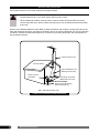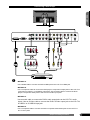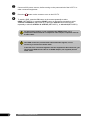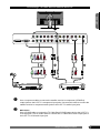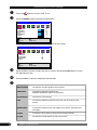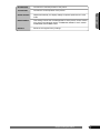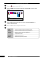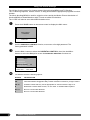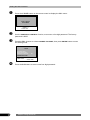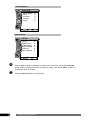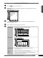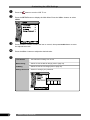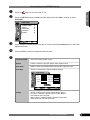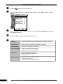
1
MUTE POWER TV/CATV PICTURE SWAP SOUND TV VIDEO COMP. PC WIDE PIP POP DIGEST - + DISP V-CHIP ATSC FAV- ZOOM WINDOW C.C. MTS SET UP EPG C.C. FAV+ FAV EDIT STILL AUDIO FOR ATSC DTV MENU AUTO CH+ VOL- ENTER VOL+ CH- SKIP SLEEP 1 2 4 5 7 8 9 00 0 CH RTN 3 6 Introducing the LCD TV Installing the LCD TV Using the LCD TV 32 LCD TV User Guide Federal Communications Commission Statement Changes or modifications not expressly approved by the manufacturer responsible for compliance could void the user authority to operate the equipment. FCC 1 ENGLISH This equipment has been tested and found to comply with the limits of a class B digital device, pursuant to Part 15 of the FCC Rules. These limits are designed to provide reasonable protection against harmful interference in a residential installation. This equipment generates, uses and can radiate radio frequency energy and, if not installed and used in accordance with the instructions, may cause harmful interference to radio communications. However, there is no guarantee that interference will not occur in a particular installation. If this equipment does cause harmful interference to radio or television reception, which can be determined by turning the equipment off and on, the user is encouraged to try to correct the interference by one or more of the following measures: 1. Reorient/Relocate the receiving antenna. 2. Increase the separation between the equipment and receiver. 3. Connect the equipment into an outlet on a circuit which is different from what the receiver is connected to. 4. Consult the dealer or an experienced radio/TV technician for help. Warnings and Precautions To prevent any injuries, the following safety precautions should be observed in the installation, use, servicing and maintenance of this equipment. Before operating this equipment, please read this manual completely, and keep it nearby for future reference. WARNING This symbol is intended to alert the user to avoid the risk of electric shock. This equipment must not be disassembled by anyone except qualified service personnel. CAUTION This symbol is intended to alert the user to the presence of important operating and maintenance instructions in the literature accompanying the appliance. To reduce the risk of fire or electric shock, do not expose this equipment to rain or moisture. ▪ ▪ ▪ ▪ TO REDUCE THE RISK OF ELECTRIC SHOCK, DO NOT REMOVE COVER (OR BACK). NO USER-SERVICEABLE PARTS INSIDE. REFER SERVICING TO QUALIFIED SERVICE PERSONNEL. Use of controls, adjustments or performance of procedures other than those specified herein may result in hazardous radiation exposure. Important Safety Instructions ▪ Do not place the equipment on any uneven or unstable carts, stands, tables, shelves etc. The equipment may fall, causing serious injury to children or adults and serious damage to the equipment itself. ▪ Use only a cart or stand recommended by the manufacturer. This equipment and recommended cart or stand should be handled with care. Quick stops, excessive force, and uneven surfaces may cause the equipment and cart/stand to overturn. ▪ Do not disable the 3-wire grounding type plug. The grounding pin on the 3-prong plug is an important feature. Removing the grounding pin will increase the risk of damaging the equipment. ▪ If you can not fit the plug into the electrical outlet, contact an electrician to install a grounding outlet. ▪ Always operate this equipment from the type of power source indicated on the rear of the serial/model plate. ▪ Never overload wall outlets and extensions. ▪ Use and handle the power cord with care. Do not place any heavy objects on the AC power cord. ▪ Do not pull the AC power cord. Do not handle the AC power cord with a wet hand. ▪ Do not touch the power cord and antenna cable during lightning. 2 Warnings and Precautions Remove the plug from the wall outlet, if the equipment will not be used for a long period of time. ▪ Do not place, use or handle this equipment near water. ▪ Never expose the equipment to liquid, rain, or moisture. Seek for service if any of the above is spilled into the equipment. ▪ Do not expose the equipment to extreme temperature or to direct sunlight, as the equipment may heat up and suffer damage. ▪ Do not install the equipment near any heat sources such as radiators, heat registers, stoves, or any other apparatus that might produce heat. ▪ Do not attempt to service the equipment yourself. ▪ Opening and removing the covers may expose you to dangerous voltage or other hazards and may void your warranty. Refer service to qualified personnel. ▪ Do not place or drop any other objects on top. ▪ Do not insert anything into the ventilation holes of your equipment. Inserting any metal or flammable objects may result to fire or electric shock. ▪ Do not place the equipment on uneven or unstable carts, stands, tables, shelves etc. The equipment may fall, causing serious injury to children or adults and serious damage to the equipment itself. Always place the equipment on the floor or on a surface that is sturdy, level, stable and strong enough to support the weight of the equipment. ▪ Do not block any ventilating openings. Leave an open space around the equipment. Never place the equipment : on a bed, sofa, rug, or any other similar surfaces; too close to drapes/curtains/walls, in a bookcase, built-in cabinet, or any other similar places that may cause poor ventilation. ▪ Always remove the power cord from the outlet before cleaning the equipment. ▪ Never use liquid or aerosol cleaners on the equipment. Clean only with a soft dry cloth. Warnings and Precautions ENGLISH ▪ 3 Outdoor Antenna Safety Instructions If an outdoor antenna is connected, follow the precautions below: ▪ An outdoor antenna should not be located in any area where it could come in contact with overhead power lines, or any other electric light or power circuits. ▪ When installing an outdoor antenna system, extreme caution should be taken to prevent contact with power lines. Direct contact with power lines may be fatal and should be avoided at all costs. Section 810 of National Electrical Code (NEC) provides information with respect to proper grounding of the mast and supporting structure, grounding of the lead-in wire to an antenna discharge unit, size of grounding conductors, location of antenna discharge unit, connection to grounding electrodes, and requirements for the grounding electrode. Antenna lead-in wire Ground clamps Antenna discharge unit (NEC section 810-20) Electric service equipment Grounding conductors (NEC section 810-20) Ground clamps Power service grounding (NEC Art250 part H) NEC : National Electrical code EXAMPLE OF OUTDOOR ANTENNA GROUNDING 4 Warnings and Precautions CONTENTS ENGLISH Federal Communications Commission Statement Warnings and Precautions Important Safety Instructions ......................................................................................... 2 Antenna Safety Instructions ........................................................................................... 4 Chapter 1 Introducing the LCD TV Key Features ................................................................................................................. 7 Package Contents ......................................................................................................... 8 Setting Your LCD TV...................................................................................................... 9 Your LCD TV .................................................................................................................. 10 Your Remote Control ..................................................................................................... 12 Chapter 2 Installing the LCD TV Connecting a TV Cable or Antenna ............................................................................... 14 Connecting a VCR ......................................................................................................... 18 Connecting a DVD Player .............................................................................................. 19 Connecting a TV Cable Box and Satellite Receiver ...................................................... 21 Connecting a Video Camera.......................................................................................... 23 Connecting a two VCRs ................................................................................................ 24 Connecting a PC ........................................................................................................... 25 Chapter 3 USING THE FEATURES Watching Your LCD ....................................................................................................... 26 Operating the Menu ....................................................................................................... 27 Setting up the Channel List ................................................................................. 29 Customizing the Picture Settings ......................................................................... 32 Customizing the Audio Settings ........................................................................... 34 Customizing the Picture Color Settings ................................................................. 35 Customizing the Display Settings ......................................................................... 36 Customizing the OSD Settings ............................................................................ 37 Customizing the MISC Settings ........................................................................... 38 Using the PIP/POP/MULTI PIP Settings................................................................ 39 Using the V-CHIP Settings (For U.S TV system only) ............................................. 40 Operating the ATSC System ............................................................................... 43 Customizing the STATION Settings ...................................................................... 45 Customizing the LOCK Settings........................................................................... 46 Customizing the CAPTION Settings ..................................................................... 47 Customizing the SETUP Settings ......................................................................... 48 TROUBLESHOOTING............................................................................................ 49 SPECIFICATION .................................................................................................... 50 PRESET MODE TIMING CHART............................................................................. 51 Troubleshooting and Specifications 5 6 Chapter 1 Introducing the LCD TV Chapter 1 Introducing the LCD TV Key Features ENGLISH Various Audio/Video terminals for external equipment connection ▪ ▪ ▪ ▪ ▪ ▪ ▪ 2 composite A/V input terminal 1 set of composite A/V output terminals 2 S-VIDEO terminal 2 set of component Video input terminals 1 VGA/AUDIO input terminal 1 HDMI/AUDIO input terminal 4 sets of Audio input terminals High Definition Multimedia Interface (HDMI) ▪ High Definition Multimedia Interface (HDMI) is a small, user-friendly interconnect that can carry up to 5 Gbps of combined video and audio in a single cable. This system eliminates the cost, complexity and confusion of multiple cables used to connect current A/V systems The built-in TV tuner to receive HD ATSC ▪ This function allows the reception of HD broadcasting without the addition of a set top box. Digital Noise Reduction ▪ This function can digitally reduce image noise to provide better picture quality. Film-Mode Detection (3:2 Reverse Pull Down) ▪ This function can automatically detect content derived from film and adjust the interlacer’s frame matching to provide a more natural-looking, clearer image of the moving picture. PIP Function ▪ This function allows viewing of video from two different sources simultaneously. Compatible with HDTV, available for 480p, 720p and 1080i HDTV video signals Chapter 1 Introducing the LCD TV 7 Package Contents Make sure all of the following contents are included. Warranty Card LCD TV H Stand Remote Control/AAA Batteries x 2 MUTE User Guide POWER TV/CATV PICTURE SWAP SOUND TV VIDEO COMP. PC WIDE PIP POP DIGEST - + DISP V-CHIP ATSC SET UP FAV- FAV+ ZOOM WINDOW C.C. MTS EPG C.C. FAV EDIT STILL AUDIO FOR ATSC DTV MENU AUTO CH+ VOL- ENTER VOL+ CH- SKIP SLEEP 1 2 4 5 7 8 9 00 0 CH RTN 3 6 Power Cord Antenna jack These items are all you need to set up and operate the LCD TV in its basic configuration. Make sure all of the following contents are included. If you are missing any items, please return this product to the original place of purchase. 8 Chapter 1 Introducing the LCD TV Setting Your LCD TV Use a supplied antenna cable to connect the VHF/UHF signal to the LCD TV’s ANT. terminal (refer to page14). ENGLISH Connect the AC power cord at the back of the TV and connect t the power cord to wall outlet. Insert the 2 batteries supplied in remote control. Step1 Slide the back cover up to open the battery compartment of the remote control. Step2 Insert two AAA size batteries. Make sure to match the (+) and ( - ) ends of the batteries with the (+) and ( - ) ends indicated in the battery compartment. Slide the cover back into place. Do not use caustic cleaners (porcelain, stainless steel, toilet, or oven cleaner etc.) on the remote, as it may suffer damage. Connect other an external A/V device (refer to page18-25). Chapter 1 Introducing the LCD TV 9 Your LCD TV Front/Top View and Controls LED The LED light indicates when the LCD TV is activated. IR Infrared Receiver (IR) MENU Press once to display the OSD (on screen display), press again to turn the OSD off. Turns the LCD TV on and into standby mode. SOURCE Chooses from different input signal sources. SELECT▲▼ Scans up and down through channels. Selects sub-menu item when in the OSD mode. VOLUME◄► Adjusts the volume up and down. Selects the main-menu item and change values for items when in the OSD mode. 10 Chapter 1 Introducing the LCD TV Rear View and Jacks ENGLISH ANT. NTSC Connects RF input from VHF/UHF antenna or cable. AV2/S-VIDEO2 IN Connects to the composite Video/S-VIDEO and Audio output jacks on external video equipment. AV1/S-VIDEO1 IN Connects to the composite Video/S-VIDEO and Audio output jacks on external video equipment. AV Output Connects to the composite A/V intput jacks on external video equipment. ANT. ATSC Connects RF input from VHF/UHF antenna or cable to receive high definition digital television. COMPONENT(Y2Pb2Pr2) IN Connects to the Component(YPbPr) video and audio output jacks on external video equipment. COMPONENT(Y1Pb1Pr1) IN Connects to the Component(YPbPr) video and audio output jacks on external video equipment. HDMI VGA VGA-LINE Y1 Pb1 Pr1 L1 R1 DVI-LINE Y2 Pb2 Pr2 L2 R2 ANT. ATSC S-VIDEO1 VIDEO AV1 AV2 S-VIDEO2 ANT. NTSC DVI_LINE Connects the AV equipment with AUDIO jack of HDMI (The AUDIO of HDMI IN is for DVI connection). VGA_ LINE Connects the satellite receiver or other AV equipment, TV Box, or PC with AUDIO jack of VGA. VGA IN Connects the satellite receiver or other AV equipment, TV Box, or PC with VGA connector. HDMI IN Connects the AV equipment with HDMI connector. Chapter 1 Introducing the LCD TV 11 Your Remote Control PICTURE Cycles through picture quality modes: STANDARD, BRIGHT, SOFT, MOVE STANDARD, MOVE BRILLIANT MUTE Mutes and restores your LCD TV sound. TV/CATV Cycles through the TV receiving signal: TV(antenna), CATV(cable) WIDE Cycles through the picture size:16:9,4:3, FULL,NATIVE -+ Changes the size of secondary picture while using the window button. DISP Displays information on the LCD TV screen such as channel and channel label. V-CHIP Turns the V-CHIP function on and off. ATSC DTV FUNCTION For ATSC TV system only. SWAP Swaps between main and sub screens in PIP/POP/MULTI PIP mode. MUTE POWER TV/CATV PICTURE SWAP TV VIDEO COMP. PC WIDE PIP POP DIGEST - + DISP V-CHIP ZOOM WINDOW C.C. MTS ATSC SET UP EPG FAV- FAV+ FAV EDIT C.C. STILL AUDIO FOR ATSC DTV MENU MENU Displays the OSD (on screen display) menu. CH+/Scans up and down through channels. SOUND AUTO Turns the LCD TV on and off. SOUND Cycles through the audio modes: STANDARD, MOVIE, SOFT TV/VIDEO/COMP./PC Selects among the video equipment connected to the video inputs of your LCD TV. PIP/POP/DIGEST Enters picture-in-picture(PIP)/ picture-outside-picture(POP)/ multiple pictures(MULTI PIP) modes WINDOW Controls or adjusts either the main screen and sub screen in PIP/POP mode. MTS Cycles through the TV Sound options: MONO/SAP/Stereo ZOOM Enters the enlarge funciton,press +/- buttons to adust the screen size gradually. CH+ VOL- ENTER VOL+ C.C. Cycles through the closed caption modes. CH- ENTER Refers to the OSD menu for detailed information. SLEEP Sets the LCD TV sleep time. 0-9 Select and switch to a channel by using 0-9 buttons. SKIP SLEEP 1 2 3 4 5 6 7 8 9 00 0 CH RTN 00 The one/two digit numbers by pressing this button. AUTO Automatically detect and store all active channels in your ares. VOL+/Adjusts the volume. SKIP Deletes the current channel. CH RTN Switch back and forth between the current and previous channel. Effective range: The remote can control the LCD TV from up to 5m away, if pointed directly at the receiver. 12 Chapter 1 Introducing the LCD TV ATSC DTV FUNCTION POWER TV/CATV PICTURE SWAP SETUP In ATSC TV mode, pressing SETUP displays the menu on the screen. ATSC Select the ATSC TV receiving the signal inputs of your LCDTV. FAV-/FAV+ Change the favorite channel up and down. ENGLISH MUTE SOUND TV VIDEO COMP. PC WIDE PIP POP DIGEST - + DISP V-CHIP C.C. MTS ATSC SET UP EPG C.C. FAV- FAV+ FAV EDIT ZOOM WINDOW FOR ATSC DTV MENU AUTO ENTER STILL No Function FAV EDIT Edit the favorite channel. CH+ VOL- C.C. In ATSC TV mode, cycles through the digital Closed Caption. STILL AUDIO AUIDO In ATSC TV mode, allows to select the audio language: English/French/ Spanish EPG In ATSC TV mode, pressing EPG displays the EPG (Electronic Program Guide) on the screen. VOL+ CH- SKIP SLEEP 1 2 3 4 5 6 7 8 9 00 0 CH RTN Chapter 1 Introducing the LCD TV 13 Chapter 2 Installing the LCD TV Refer to the owner’s manual of any external equipment to be connected. When connecting any external equipment, do not connect any AC power cords to wall outlets until all other connections are completed. Connecting a TV Cable or Antenna Antenna Connection The antenna requirements for good color TV reception are more important than those for a black & white TV reception. For this reason, a good quality outdoor antenna is strongly recommended. The following is a brief explanation of the type of connection that is provided with the various antenna systems. ■ A 75-ohm system is generally a round cable (not included) with Ftype connector that can easily be attached to a terminal without tools. F-type connector 75-ohm coaxial cable (round) ■ A 300-ohm system is a flat twin-lead cable (not included) that can be attached to a 75-ohm terminal through a 300-75-ohm adapter (not included). 300-ohm twin-lead cable (flat) Use one of the following two diagrams when connecting an outdoor antenna. A: Shows how to use a VHF/UHF combination outdoor antenna. B: Shows how to use a separate VHF and/or UHF outdoor antenna. 14 Chapter 2 Installing the LCD TV A. Combination VHF/UHF antenna VHF/UHF Antenna 300-ohm twinlead cable VHF/UHF Antenna ENGLISH 300/75-ohm adapter (not included) 75-ohm coaxial cable UHF Antenna B. Separate VHF and/or UHF antennas Combiner 300-ohm twin(not included) lead cable OUT IN VHF Antenna 75-ohm coaxial cable 300-ohm twinlead cable Chapter 2 Installing the LCD TV 15 Cable TV (CATV) Connection This reminder is provided to call the CATV system installer’s attention to Article 820-40 of the National Electrical Code (NEC) that provides guidelines for proper grounding and, in particular, specifies that the cable ground shall be connected to the grounding system of the building accurately, or as close to the point of cable entry as possible. Use of this TV for other than private viewing of programs broadcasted on UHF, VHF or transmitted by cable companies for the use of the general public may require authorization from the broadcast/cable company, and/ or program owner. ■ A 75-ohm coaxial cable connector is built into the set for easy hookup. When connecting the 75-ohm coaxial cable to the set, connect the 75ohm cable into the ANT. terminal. ■ Some cable TV companies offer premium pay channels. Since the signals of these premium pay channels are scrambled, a cable TV converter/descrambler is generally provided to the subscriber by the cable TV company. This converter/descrambler is necessary for normal viewing of scrambled channels. (Set your TV to channel 3 or 4, typically one of these channels is used. If this is unknown, consult your cable TV company.) For more specific instructions on installing cable TV, consult your cable TV company. One possible method of connecting the coverter/descrambler provided by your cable TV company is shown in the diagram below. RF switch (not included) OUT 2 set signal splitter (not included) A IN B Cable TV Line Cable TV converter/ descrambler (not included) ■ The RF switch (not included) is required to provide two inputs (A and B). Setting the RF switch to position A allows viewing of all unscrambled channels by using the TV channel keys. ■ Setting the RF switch to position B allows viewing of all scrambled channels via the converter/descrambler by using the converter channel keys. 16 Chapter 2 Installing the LCD TV Use a supplied antenna cable to connect the VHF/UHF signal to the LCD TV’s ANT. terminal. ENGLISH Connect the AC power cord at the back of the TV and connect the power cord to wall outlet. Press the button on the remote to turn on the LCD TV. Always disconnect the LCD TV from the power outlet when the LCD TV will not be used for a long period of time. The POWER button on the front panel is only used for switching the LCD TV into standby, it does not disconnect the device from the main voltage. To completely disconnect the main voltage, please remove the power plug from the socket. Press the TV button on the remote. Chapter 2 Installing the LCD TV 17 Connecting a VCR HDMI VGA VGA-LINE Y1 Pb1 Pr1 L1 R1 DVI-LINE Y2 Pb2 Pr2 L2 R2 A ANT. ATSC S-VIDEO1 VIDEO AV1 AV2 S-VIDEO2 ANT. NTSC B METHOD A: Use an audio cable to connect the VCR’s audio output jacks to the LCD TV’s audio inputs. Use an S-Video cable to connect the VCR’s S-video output jack to the LCD TV’s S-VIDEO1 or S-VIDEO2 input jack. METHOD B: Use a composite cable to connect the VCR’s composite video/audio jacks to the LCD TV’s composite video/audio jacks. 18 Connect all AC power sources, before turning on the power switch of the LCD TV or other connected equipment. Press the button on the remote to turn on the LCD TV. To watch a videotape, press the VIDEO button on the remote repeatedly to select S-VIDEO1/S-VIDEO2( METHOD A), or AV1/AV2 (METHOD B). Chapter 2 Installing the LCD TV Connecting a DVD Player ENGLISH HDMI VGA VGA-LINE Y1 Pb1 Pr1 L1 R1 DVI-LINE Y2 Pb2 Pr2 L2 R2 ANT. ATSC S-VIDEO1 VIDEO AV1 AV2 S-VIDEO2 ANT. NTSC /Pb /Pr A C B D /Pb /Pr DVD PLAYER METHOD A: Use a HDMI cable to connect the DVD’s HDMI jack to the LCD TV’s HDMI jack. METHOD B: Use a component cable to connect the DVD player’s component output jacks to the LCD TV’s component (Y1Pb1Pr1 or Y2Pb2Pr2) input jacks. Use an audio cable to connect the DVD player’s component audio jacks to the LCD TV’s audio input jacks. METHOD C: Use an audio cable to connect the DVD’s audio output jacks to the LCD TV’s audio inputs. Use an S-Video cable to connect the DVD’s S-video output jack to the LCD TV’s S-VIDEO1 or S-VIDEO2 input jack. METHOD D: Use a composite cable to connect the DVD’s composite video/audio jacks to the LCD TV’s AV1 or AV2 jacks. Chapter 2 Installing the LCD TV 19 Connect all AC power sources, before turning on the power switch of the LCD TV or other connected equipment. Press the button on the remote to turn on the LCD TV. To watch a DVD, press the PC button on the remote repeatedly to select HDMI ( METHOD A), or press the COMP. button on the remote repeatedly to select Y1Pb1Pr1/Y2Pb2Pr2 ( METHOD B), or press the VIDEO button on the remote repeatedly to select S-VIDEO1/ S-VIDEO2( METHOD C), or AV1/AV2(METHOD D). For best picture quality, if your equipment has HDMI output, use a component cable instead of a component video output, composite video or S-video cable. The HDMI connector provides both video and audio signals, it’s not necessary to connect the audio cable. If the LCD TV is connected together with the equipment’s DVI connecter, you will need an HDMI-to-DVI cable or an HDMI adapter (not supplied) and an audio cable. 20 Chapter 2 Installing the LCD TV Connecting a TV Cable Box and Satellite Receiver ENGLISH HDMI VGA VGA-LINE Y1 Pb1 Pr1 L1 R1 DVI-LINE Y2 Pb2 Pr2 L2 R2 ANT. ATSC S-VIDEO1 VIDEO AV1 AV2 S-VIDEO2 ANT. NTSC /Pb /Pr B A B /Pb /Pr Use a component cable to connect the satellite receiver’s component (Y2Pb2Pr2) output jacks to the LCD TV’s component input jacks. Use an audio cable to connect the satellite receiver’s component audio jacks to the LCD TV’s audio input jacks. METHOD A: Use a D-SUB cable to connect the TV Cable Box’s D-SUB output jack to the LCD TV’s VGA input jack. Use an audio cable to connect the TV Cable Box’s audio output jack to the LCD TV’s VGA audio input jack. Chapter 2 Installing the LCD TV 21 METHOD B: Use an audio cable to connect the TV Cable Box’s audio output jacks to the LCD TV’s audio inputs. Use an S-Video cable to connect the TV Cable Box’s S-video output jack to the LCD TV’s S-VIDEO2 input jack. 22 Connect all AC power sources, before turning on the power switch of the LCD TV or other connected equipment. Press the button on the remote to turn on the LCD TV. To watch programs via satellite receiver, press the COMP. button on the remote repeatedly to select Y2Pb2Pr2. To watch TV via TV cable box, press the PC button on the remote repeatedly to select VGA ( METHOD A), or press the VIDEO button on the remote repeatedly to select S-VIDEO2 ( METHOD B). Chapter 2 Installing the LCD TV Connecting a Video Camera ENGLISH HDMI VGA VGA-LINE Y1 Pb1 Pr1 L1 R1 DVI-LINE Y2 Pb2 Pr2 L2 R2 A ANT. ATSC S-VIDEO1 VIDEO AV1 AV2 S-VIDEO2 ANT. NTSC B METHOD A: Use an audio cable to connect the video camera’s audio output jacks to the LCD TV’s audio inputs. Use an S-Video cable to connect the video camera’s S-video output jack to the LCD TV’s S-VIDEO1 or S-VIDEO2 input jack. METHOD B: Use a composite cable to connect the video camera’s composite video/audio jacks to the LCD TV’s AV1 or AV2 jacks. Connect all AC power sources, before turning on the power switch of the LCD TV or other connected equipment. Press the button on the remote to turn on the LCD TV. To watch a video vis camera, press the VIDEO button on the remote repeatedly to select S-VIDEO1/S-VIDEO2( METHOD A), or AV1/AV2 (METHOD B). Not all cameras have the ability to connect to a TV. Please check your video camera user guide for compatibility. Chapter 2 Installing the LCD TV 23 Connecting two VCRs HDMI VGA-LINE Y1 Pb1 Pr1 L1 R1 DVI-LINE Y2 Pb2 Pr2 L2 R2 VGA 1 ANT. ATSC S-VIDEO1 AV2 VIDEO AV1 S-VIDEO2 ANT. NTSC 2 Use a composite cable to connect the VCR1’s composite video/audio input jacks to the LCD TV’s composite video/audio output jacks. Use a composite cable to connect the VCR2’s composite video/audio outputjacks to the LCD TV’s AV2 input jacks. Connect all AC power sources, before turning the LCD TV’s power switch on. Press the button on the remote to turn on your LCD TV. Through connected two VCRs, you can record one VCR to the other. You can watch a videotape at the same time. Use the VIDEO Output of the LCD TV to connect other TV or Display, the input source of LCD TV can be one of TV, AV1, and AV2. 24 Chapter 2 Installing the LCD TV Connecting a PC ENGLISH HDMI VGA VGA-LINE Y1 Pb1 Pr1 L1 R1 DVI-LINE Y2 Pb2 Pr2 L2 R2 ANT. ATSC S-VIDEO1 VIDEO AV1 AV2 S-VIDEO2 ANT. NTSC Use a D-SUB cable to connect the PC’s D-SUB output jack to the LCD TV’s VGA input jack. Use an audio cable to connect the PC’s audio output jacks to LCD TV’s. Connect all AC power sources, before turning on the power switch of the LCD TV or other connected equipment. Press the button on the remote to turn on the LCD TV. Press the PC button on the remote repeatedly to select VGA. Chapter 3 Using the LCD TV 25 Chapter 3 USING THE FEATURES Watching Your LCD Press the button to turn the LCD TV on. Press the TV button to enter TV mode, or press the SOURCE button on the top of TV to select the TV. Press the CH+- buttons to change channels, or use the 0-9 buttons to choose a channel. Press the CH RTN button to alternate back and forth between two channels. TV VIDEO COMP. PC WIDE PIP POP DIGEST - + DISP V-CHIP C.C. MTS ATSC SET UP EPG C.C. FAV- FAV+ FAV EDIT 12 If the LCD TV does not display any picture, check all the connections. Chapter 3 Using the LCD TV ZOOM WINDOW 6 STILL AUDIO FOR ATSC DTV MENU AUTO CH+ 5 Press the DISPLAY button to display information such as the channel and channel label. Press the DISPLAY button again to hide the information. 1 SOUND 2 Press the VOL+- buttons to adjust the volume. Press the MUTE button to turn the sound off, press again to turn the sound on. TV 26 POWER MUTE TV/CATV PICTURE SWAP VOL- ENTER VOL+ 3 CH- SKIP SLEEP 1 2 3 4 5 6 7 8 9 00 0 CH RTN 4 Operating the Menu Press the button to turn the LCD TV on. ENGLISH To select the signal source, press the MENU button on the remote control. The main menu will appear on the screen. Use the VOL+- buttons to select your main menu option. IMAGE MENU: MAIN MENU : IMAGE MAIN MENU : IMAGE BRIGHTNESS CONTRAST SATURATION HUE SHARPNESS PHASE CLOCK 29 35 22 0 16 0 0 : SELECT MENU : EXIT : SELECT ITEM ENTER: NEXT : SELECT MENU : EXIT page 1 ► ► ► STD ► H POSITION V POSITION AUTO ADJUST IMAGE MODE RECALL : SELECT ITEM ENTER: NEXT page 2 AUDIO MENU: MAIN MENU : AUDIO BASS TREBLE BALANCE VOLUME 11 11 0 11 ► RECALL : SELECT MENU : EXIT : SELECT ITEM ENTER: NEXT RGB MENU: MAIN MENU : RGB COLOR TEMP RED GREEN BLUE RECALL : SELECT MENU : EXIT USER 0 0 0 ► : SELECT ITEM ENTER: NEXT Chapter 3 Using the LCD TV 27 DISPLAY MENU: MAIN MENU : DISPLAY DISPLAY MODE: MAIN SOURCE: SUB SOURCE: SWAP MENU SELECT H POSITION V POSITION SINGLE TV VGA ► ► ► : SELECT MENU : EXIT : SELECT ITEM ENTER: NEXT OSD MENU: MAIN MENU : OSD LANGUAGE TRANSPARENCY OSD TIME OUT ENGLISH 8 15 SEC : SELECT MENU : EXIT : SELECT ITEM ENTER: NEXT MISCELLANEOUS MENU: MAIN MENU : MISC SLEEP ASPECT RATIO NOISE REDUCTION IMAGE FREEZE CCD TYPE CCD : SELECT MENU : EXIT OFF FULL MEDIUM OFF CC1 OFF : SELECT ITEM ENTER: NEXT TV SET MENU: MAIN MENU : TV SET STATION CHANNEL EDIT FAVORITE CH MODE STATUS MTS CH SCAN : SELECT MENU : EXIT 28 CATV 46 ► NORMAL ADD MONO ► : SELECT ITEM ENTER: NEXT Use the CH+- buttons to highlight an option of the sub-menu, and press the ENTER button. While in adjustment mode, text will turn red, and use the VOL+- buttons to change the value of the item. Press the MENU button to exit the menu. Chapter 3 Using the LCD TV Setting up the Channel List Automatically scans and stores all the TV channels With the LCD TV connected to a television programming source, press the TV button on the remote control. Press the MENU button on the remote control to display the Main menu, and use the VOL+- buttons to select the TV SET, and press the ENTER button. MAIN MENU : TV SET STATION CHANNEL EDIT FAVORITE CH MODE STATUS MTS CH SCAN : SELECT MENU : EXIT CATV 46 ► NORMAL ADD MONO ► : SELECT ITEM ENTER: NEXT Press the CH+- buttons to select CH MODE, and use the VOL+- buttons to select the NORMAL. Press the CH+- buttons to select CH SCAN, and press the ENTER button. The CH SCAN automatically creates a list of receivable channels. Press the MENU button at any time to interrupt the memorization process.(the list cannot be created if interrupted) CH SEARCH PRESS MENU KEY TO STOP Chapter 3 Using the LCD TV 29 ENGLISH Hiding the TV channels Press the MENU button on the remote control to display the Main menu, and use the VOL+- buttons to select the TV SET, and press the ENTER button. Press the CH+- buttons to select CHANNEL, then press the VOL+- to select the channel you choose to hide. MAIN MENU : TV SET STATION CHANNEL EDIT FAVORITE CH MODE STATUS MTS CH SCAN CATV 46 ► NORMAL ADD MONO ► : SELECT MENU : EXIT : SELECT ITEM ENTER: NEXT Press the CH+- buttons to select STATUS, then Use the VOL+- buttons to select the ERASE option. MAIN MENU : TV SET STATION CHANNEL EDIT FAVORITE CH MODE STATUS MTS CH SCAN : SELECT MENU : EXIT CATV 46 ► NORMAL ADD MONO ► : SELECT ITEM ENTER: NEXT Repeat steps 1~3 to hide other channels. To add the hided channels, please repeat steps 1-3 and use the VOL+- buttons to select the ADD option. Hided channels can only be accessed with the 0-9 buttons. 30 Chapter 3 Using the LCD TV Setting the Favorite TV channels Press the MENU button on the remote control to display the Main menu, and use the ENGLISH VOL+- buttons to select the TV SET, and press the ENTER button. MAIN MENU : TV SET STATION CHANNEL EDIT FAVORITE CH MODE STATUS MTS CH SCAN CATV 46 ► NORMAL ADD MONO ► : SELECT MENU : EXIT : SELECT ITEM ENTER: NEXT Press the CH+- buttons to select EDIT FAVORITE, and press the ENTER button to display the EDIT FAVORITE menu: EDIT FAVORITE CH PR 01 02 03 04 05 06 07 08 09 10 11 12 13 14 15 16 17 18 19 20 CH ___ ___ ___ ___ ___ ___ ___ ___ ___ ___ ___ ___ ___ ___ ___ ___ ___ ___ ___ ___ PR 21 22 23 24 25 26 27 28 29 30 31 32 33 34 35 36 37 38 39 40 CH+ CH- CH ___ ___ ___ ___ ___ ___ ___ ___ ___ ___ ___ ___ ___ ___ ___ ___ ___ ___ ___ ___ PR 41 42 43 44 45 46 47 48 49 40 51 52 53 54 55 56 57 58 59 60 : PR SELECT : EXIT CH ___ ___ ___ ___ ___ ___ ___ ___ ___ ___ ___ ___ ___ ___ ___ ___ ___ ___ ___ ___ PR 61 62 63 64 65 66 67 68 69 70 71 72 73 74 75 76 77 78 79 80 CH ___ ___ ___ ___ ___ ___ ___ ___ ___ ___ ___ ___ ___ ___ ___ ___ ___ ___ ___ ___ PR 81 82 83 84 85 86 87 88 89 90 91 92 93 94 95 96 97 98 99 1H CH ___ ___ ___ ___ ___ ___ ___ ___ ___ ___ ___ ___ ___ ___ ___ ___ ___ ___ ___ ___ : CH SELECT ENTER: BACK RETURN:RECALL Press the VOL+- buttons to select the sequence of the favorite channel, and use the VOL+- buttons to select the favorite channel. Press the ENTER button to return to the TV OSD menu. Press the RETURN button to RECALL it again. Press the CH+- buttons to select CH MODE, use the VOL+- buttons to select the TV source to be FAVORITE. Chapter 3 Using the LCD TV 31 Customizing the Picture Settings Press the button to turn the LCD TV on. Press the MENU button to display the Main Menu : MAIN MENU : IMAGE BRIGHTNESS CONTRAST SATURATION HUE SHARPNESS PHASE CLOCK 29 35 22 0 16 0 0 : SELECT MENU : EXIT : SELECT ITEM ENTER: NEXT Press the VOL+-button, the other item will appear on the screen. MAIN MENU : IMAGE ► ► ► STD ► H POSITION V POSITION AUTO ADJUST IMAGE MODE RECALL : SELECT MENU : EXIT 32 : SELECT ITEM ENTER: NEXT Press the CH+- buttons to select the item to control, then press ENTER button to enter into adjustment mode. Press the VOL+- buttons to adjust the desired value. BRIGHTNESS Controls the overall brightness of the picture. CONTRAST Controls the difference between the brightest and darkest regions of the picture. SATURATION Controls the color intensity. HUE Controls the difference between the green and red regions of the picture. SHARPNESS Increase this setting to see crisp edges in the picture; decrease it for soft edges. PHASE Increase the focus clarity in the picture and image stability. CLOCK Controls the overall frequency rate of the picture. Chapter 3 Using the LCD TV Controls the horizontal position of the picture. V POSITION Controls the vertical position of the picture. AUTO ADJUST Adjusts automatically the display settings to optimize performance in VGA mode. IMAGE MODE This setting controls the overall appearance of the picture, and is chosen from among the following options: STANDARD, BRIGHT, SOFT, MOVE STANDARD, MOVE BRILLIANT. RECALL Restores the original factory settings. Chapter 3 Using the LCD TV ENGLISH H POSITION 33 Customizing the Audio Settings Press the button to turn the LCD TV on. Press the MENU button to display the Main Menu.Press the VOL+- buttons to select AUDIO. MAIN MENU : AUDIO BASS TREBLE BALANCE VOLUME 11 11 0 11 ► RECALL : SELECT MENU : EXIT 34 : SELECT ITEM ENTER: NEXT Press the CH+- buttons to select the item to control, then press ENTER button to enter into adjustment mode. Press the VOL+- buttons to adjust the desired value. BASS Controls the relative intensity of lower-pitched sounds. TREBLE Controls the relative intensity of higher pitched sounds. BALANCE Adjusts the relative volume of the speakers in a multiplespeaker system. VOLUME Changes the audio volume. RECALL Restores the original factory settings. Chapter 3 Using the LCD TV Customizing the Picture Color Settings Press the button to turn the LCD TV on. ENGLISH Press the MENU button to display the Main Menu.Press the VOL+- buttons to select RGB. MAIN MENU : RGB COLOR TEMP RED GREEN BLUE RECALL : SELECT MENU : EXIT USER 0 0 0 ► : SELECT ITEM ENTER: NEXT Press the CH+- buttons to select the item to control, then press ENTER button to enter into adjustment mode. Press the VOL+- buttons to adjust the desired value. COLOR TEMP Controls the red, green and blue components of the picture’s white color: STANDARD, WARM, COOL, and USER. WARM: gives the white color a red tint. COOL: gives the white color a blue tint. USER: adjusts the RGB color value manually. If COLOR MODE is set to ‘User’, all options may be adjusted according to personal preference; all settings are saved. RED Adjusts the red color setting. GREEN Adjusts the green color setting. BLUE Adjusts the blue color setting. RECALL Restores the original factory settings. Chapter 3 Using the LCD TV 35 Customizing the DISPLAY Settings Press the button to turn the LCD TV on. Press the MENU button to display the Main Menu.Press the VOL+- buttons to select DISPALY. MAIN MENU : DISPLAY DISPLAY MODE: MAIN SOURCE: SUB SOURCE: SWAP MENU SELECT H POSITION V POSITION : SELECT MENU : EXIT 36 SINGLE TV VGA ► ► ► : SELECT ITEM ENTER: NEXT Press the CH+- buttons to select the item to control, then press ENTER button to enter into adjustment mode. Press the VOL+- buttons to adjust the desired value. DISPLAY MODE Select the screen mode: SINGLE, PIP, POP, and MULTI PIP. SINGLE: switches to single screen. PIP: switches to picture outside picture screen POP: switches to picture in picture screen MULTI PIP: switches to multiple screen MAIN SOURCE Selects the main source as TV/VIDEO 1/VIDEO 2/S-Video 1/S-Video 2 SUB SOURCE Selects the sub source as VGA, HDMI,and Y1Pb1Pr1/Y2Pb2Pr2, ATSC mode. SWAP Switches between the main screen and sub screen. H POSITION Controls the horizontal position of the second screen. V POSITION Controls the vertical position of the second screen. Chapter 3 Using the LCD TV Customizing the OSD Settings Press the button to turn the LCD TV on. ENGLISH Press the MENU button to display the Main Menu.Press the VOL+- buttons to select OSD. MAIN MENU : OSD LANGUAGE TRANSPARENCY OSD TIME OUT : SELECT MENU : EXIT ENGLISH 8 15 SEC : SELECT ITEM ENTER: NEXT Press the CH+- buttons to select the item to control, then press ENTER button to enter into adjustment mode. Press the VOL+- buttons to adjust the desired value. LANGUAGE Allows selection of the language used on all the on-screen menus:Traditional CHINESE / SimplifiedCHINESE / FRENCH /GERMAN/SPANISH /KOREAN/ENGLISH. TRANSPARENCY Controls the translucence of the on-screen menus’s background: 0/1/2/......................./13/14/15. OSD TIME OUT Allows selection of the display time of the on-screen menu:: 10/15/20/25/30 seconds Chapter 3 Using the LCD TV 37 Customizing the MISC Settings Press the button to turn the LCD TV on. Press the MENU button to display the Main Menu.Press the VOL+- buttons to select MISC. MAIN MENU : MISC SLEEP ASPECT RATIO NOISE REDUCTION IMAGE FREEZE CCD TYPE CCD : SELECT MENU : EXIT OFF FULL MEDIUM OFF CC1 OFF : SELECT ITEM ENTER: NEXT Press the CH+- buttons to select the item to control, then press ENTER button to enter into adjustment mode. Press the VOL+- buttons to adjust the desired value. SLEEP Allows selection of the time that elapaes before the TV shuts off automatically: Off/10/20/30 …./100/110/120minutes ASPECT RATIO Controls how the image is fit inside the screen: NATIVE,FULL,4:3,16:9 NOISE REDUCTION Allows adjustment for the fine tune level by hand if signal is too weak or picture is blurry: OFF, WEAK, MEDIUM, STRONG 38 IMAGE FREEZE Freezes and restores the picture. CCD TYPE Allows selection of the closed caption modes: CCD1-/CCD4 : Displays a printed version of the dialog or sound effects of the program. TEXT1-TEXT4: Displays station information presented using either half or the whole screen. CCD Turns the subtitle control on and off. Chapter 3 Using the LCD TV Using the PIP/POP/MULTI PIP Settings The PIP/POP/MULTI PIP feature allows simultaneous viewing of video from two sources (TV, VCR, DVD etc). Only one source’s audio is played at a time; the user may select which source’s audio is heard. ENGLISH Press the PIP button on the remote control to enter picture-in-picture mode, press again to exit PIP mode. MAIN SUB Press the POP button on the remote control to enter picture-outside-picture mode, press again to exit POP mode. SUB MAIN Press the DIGEST button on the remote control to enter multiple pictures mode, press again to exit MULTI PIP mode. SUB MAIN The input source of the main window can be one of VGA, HDMI, YPbPr, ATSC and the input source of sub window will be one of AV, S-VIDEO, and TV. Chapter 3 Using the LCD TV 39 Using the V-CHIP Settings The US has 2 rating system for viewing content: Movie blocking(MPAA) and TV Blocking. The TV Blocking conjuncts with the V-CHIP to help parents block inappropriate programs from their children. The Movie blocking(MPAA) is used for original movies rated by the Motion Picture Association of America(MPAA) as broadcasted on cable TV and not edited for television. The V-CHIP can also be set to block MPAA-rated movies. Press the V-CHIP button on the remote control to display the Main menu: PARENTAL CONTROL INPUT 4 DIGITS PIN NUMBER ____ PRESS 0...9 V-CHIP: EXIT Use the PARENTAL CONTROL function, must enter a four-digit password. The factory password is 0000. Use the CH+- buttons to select the PARENTAL CONTROL, then Use the VOL+buttons to select the ON option to turn the PARENTAL CONTROL functions on. PARENTAL CONTROL SETUP TV GUIDELINES MPAA GUIDELINES PARENTAL CONTROL CHANGE PIN CODE ON ▼▲◄►: SELECT ENTER : NEXT 40 V-CHIP: BACK The MPAA includes the following options: RATING DESCRIPTION G General Audiences. Movie is appropriate for all ages. PG Parental Guidance Suggested. May contain material not suited for younger viewers PG-13 Contains content that may not be appropriate for viewers under the age of 13. R Restricted. Contains adult content, no one under 17 admitted without parent. NC-17 No one 17 and under admitted. X No one 17 and under admitted. Chapter 3 Using the LCD TV The TV GUIDELINE has 2 rating methods: Content-Based Rating and Age-Based Rating. The TV GUIDELINE includes the following options: AGE-BASED DESCRIPTION TV-Y All children TV-Y7 Directed to children age 7 and older TV-G General Audience TV-PG Parental Guidance suggested TV-14 Parents strongly cautioned TV-MA Mature Audience only ENGLISH RATING CONTENT-BASED RATING DESCRIPTION FV Fantasy violence D Suggestive dialogue L Strong language S Sexual situations V Violence CONTENT-BASED FV D L S V TV-PG TV-14 AGE-BASED TV-Y TV-Y7 TV-G TV-MA : To block programs by both content and age. Usethe VOL+- buttons or the CH+- buttons to select the rating you want and press the ENTER button to select BLOCK or UNBLOCK. Chapter 3 Using the LCD TV 41 Setting the New Password Press the V-CHIP button on the remote control to display the Main menu: PARENTAL CONTROL INPUT 4 DIGITS PIN NUMBER ____ PRESS 0...9 V-CHIP: EXIT Use the PARENTAL CONTROL function, must enter a four-digit password. The factory password is 0000. Pressthe CH+- buttons to select CHANGE PIN CODE, then press ENTER button to enter into setting mode. PARENTAL CONTROL SETUP TV GUIDELINES MPAA GUIDELINES PARENTAL CONTROL CHANGE PIN CODE ON ▼▲◄►: SELECT ENTER : NEXT 42 V-CHIP: BACK Press the 0-9 buttons to enter a new four-digit password. Chapter 3 Using the LCD TV Operating the ATSC System Press the ENGLISH Use a supplied antenna cable to connect the ATSC signal to the LCD TV’s ANT.ATSC terminal. button to turn the LCD TV on. TV/CATV PICTURE SWAP Use the CH+- buttons to select your main menu option. the item. STATION MENU: STATION ► ► ► ► ► Channel Scan Channel Edit Signal Strength Antenna Cable POWER MUTE Press the ATSC button, press the SETUP button on the remote control. The main menu will appear on the screen. 3 SOUND TV VIDEO COMP. PC WIDE PIP POP DIGEST - + DISP V-CHIP ATSC FAV- ZOOM WINDOW C.C. MTS SET UP EPG C.C. FAV+ FAV EDIT STILL AUDIO FOR ATSC DTV MENU AUTO CH+ VOL- ENTER VOL+ CH- OK SETUP LOCK MENU: LOCK Lock On/Off Movie Rating TV Rating Change Password OK SKIP SLEEP 1 2 3 4 5 6 7 8 9 00 0 CH RTN ► ► ► ► SETUP Chapter 3 Using the LCD TV 43 CAPTION MENU: CAPTION Caption On/Off Option ► ► Font Setup Font Style Analog ► ► ► OK SETUP SETUP MENU: SETUP Opacity SPDIF Format Default Setting Audio Language Time Zone Menu Language OK 44 ► ► ► ► ► ► SETUP Use the CH+- buttons to highlight an option of the sub-menu, and press the ENTER button. While in adjustment mode, text will turn purple, and use the VOL+- buttons to change the value of the item. Press the SETUP button to exit the menu. Chapter 3 Using the LCD TV Customizing the STATION Settings Press the button to turn the LCD TV on. ENGLISH Press the SETUP button to display the Main Menu.Press the VOL+- buttons to select STATION. STATION Channel Scan Channel Edit Signal Strength Antenna Cable OK ► ► ► ► ► SETUP Press the CH+- buttons to select the item to control, then press ENTER button to enter into adjustment mode. Press the VOL+- buttons to adjust the desired value. Channel Scan Automatically creates a list of receivable channels. ▲ ▼ SETUP STOP Channel Edit Adds/removes channels. SETUP Signal Strength Allows adjustement for the reception quality if signal is too weak or picture is blurry. Antenna Selects the antenna or cable signal: AIR/Cable/Auto. Cable Select the TV system: STD/HRC/IRC(STD, HRC and IRC identify various types of cable TV system) Chapter 3 Using the LCD TV 45 Customizing the LOCK Settings Press the button to turn the LCD TV on. Press the SETUP button to display the Main Menu.Press the VOL+- buttons to select LOCK. SETUP Press the CH+- buttons to select the item to control, then press ENTER button to enter into adjustment mode. Press the VOL+- buttons to adjust the desired value. Lock On/Off Turns Movie/TV Rating Lock on/off. Movie Rating Selects to use the Movie ratings (refer to page 39). TV Rating Selects to use the TV ratings (refer to page 40). Change Password Selects to change your password. Enter Password 46 Chapter 3 Using the LCD TV Customizing the CAPTION Settings Press the button to turn the LCD TV on. ENGLISH Press the SETUP button to display the Main Menu.Press the VOL+- buttons to select CAPTION. CAPTION Caption On/Off Option Font Setup Font Style Analog OK ► ► ► ► ► SETUP Press the CH+- buttons to select the item to control, then press ENTER button to enter into adjustment mode. Press the VOL+- buttons to adjust the desired value. Caption On/Off Turns the Closed Caption on/off. Option Allows to select the program option under Caption vision. Font Setup Allows to selet the Closed Caption settings:By Program/By User Font Style Allows to customise the Closed Caption settings: FONT STYLE Size Bg Color Style Bg Opacity Fg Color Edge Type Fg Opacity Edge Color Apply ▲▼ Analog ◄► Allows to select basic analog closed caption options: CC1-/CC4 : Displays a printed version of the dialog or sound effects of the program. TEXT1-TEXT4: Displays station information presented using either half or the whole screen. Chapter 3 Using the LCD TV 47 Customizing the SETUP Settings Press the button to turn the LCD TV on. Press the SETUP button to display the Main Menu.Press the VOL+- buttons to select SETUP. SETUP Opacity SPDIF Format Default Setting Audio Language Time Zone Menu Language 48 OK ► ► ► ► ► ► SETUP Press the CH+- buttons to select the item to control, then press ENTER button to enter into adjustment mode. Press the VOL+- buttons to adjust the desired value. Opacity Controls the translucence of on-screen menus: Opacity1-Opacity6. SPDIF Format Allows to select the digital sound format: AC-3/PCM. Default Settting Restores the original factory settings. Audio Language Allows to select the audio language: English/French/Spanish/Portuguese Time Zone Allows to select the time zone: Eastern /Central/Mountain/Pacific/ Alaska/Hawaii. Menu Language Allows selection of the language used on the on-screen menu: English/French/Spanish/Portuguese Chapter 3 Using the LCD TV TROUBLESHOOTING TROUBLESHOOTING ENGLISH Before consulting service personnel, check the following chart for a possible cause of the trouble and for a possible solution. TV will not turn on Make sure the power cord is plugged in, then press the button on the remote. The batteries in the remote control may be exhausted. Replace the batteries. No picture, no sound Check the interface cable between TV and antenna/cable TV. Press the button on the remote. Press the TV button on the remote, then press other input source button to select the connected video sources. Poor picture, sound OK Check the interface cable between TV and antenna/cable TV. Try another channel, the station may have broadcast difficulties. Adjust the Brightness/Contrast options in the VIDEO ADJUST Menu. Picture OK, poor sound Sound may be muted. Press the MUTE button on the remote. Press the TV button on the remote, then press the VOL+ button to increase the volume. VOLUME 50 Audio noise Move any infrared equipment away from the TV. Troubleshooting and Specifications 49 SPECIFICATION TROUBLESHOOTING 50 Stand Type H Stand Panel System 32 inch Display Resolution 1366 pixels(horizontal) x 768 pixels (vertical) Television System NTSC and ATSC Antenna Input 75 Ω unbalanced VIDEO IN 2 AV OUT 1 S-VIDEO 2 HDMI/AUDIO 1 YPbPr 2 VGA/AUDIO 1 AUDIO(L/R) IN 4 AUDIO OUT 1 SPEAKER OUT 10 W x 2 POWER SOURCE (Power consumption(Max)) 200 W DIMENSION 38.18 inch (W) x 23.03 inch (H) x 7.18 inch (D) WEIGHT 21 KG Troubleshooting and Specifications Preset Mode Mode Timing Timing ChartG Chart TPreset ENGLISH The screen image has been optimized during manufacture for the display modes listed below. If the signal from the system equals the standard signal mode, the screen is adjusted automatically. If the signal from the system doesn’t equal the standard signal mode, adjust the mode by referring to your videocard user guide otherwise there may be no video, For the display modes listed below, the screen image has been opimized during manufacturer. Video signal: (VGA/DVI VESA Standard) Resolution (Dot X Line) Vertical Frequency(Hz) Horizontal Frequency(kHz) Pixel Frequency 640 x 350 85 37.9 31.500 640 x 400 85 37.9 31.500 720 x 400 85 37.9 35.500 640 x 480 60 31.5 25.175 72 37.9 31.500 75 37.5 31.500 85 43.3 36.000 56 35.1 36.000 60 37.9 40.000 72 48.1 50.000 75 46.9 49.500 85 53.7 56.250 60 48.4 65.000 70 56.5 75.000 75 60.0 78.750 85 68.7 94.500 1152 x 864 75 67.5 108.000 1280 x 960 60 60.0 108.000 1280 x 1024 60 64.0 108.000 800 x 600 1024 x 768 32” LCD TV ATSC B english 1.5 3/28/06 Troubleshooting and Specifications 51