1
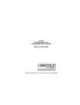
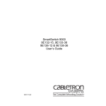
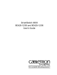
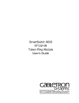
CTP100T
COAXIAL TO TWISTED PAIR
10BASE-T MEDIA ADAPTER
USER’S MANUAL
CABLETRON SYSTEMS, P. O. Box 5005, Rochester, NH 03866-5005
NOTICE
Cabletron Systems reserves the right to make changes in specifications
and other information contained in this document without prior notice.
The reader should in all cases consult Cabletron Systems to determine
whether any such changes have been made.
The hardware, firmware, or software described in this manual is subject
to change without notice.
IN NO EVENT SHALL CABLETRON SYSTEMS BE LIABLE FOR ANY
INCIDENTAL, INDIRECT, SPECIAL, OR CONSEQUENTIAL
DAMAGES WHATSOEVER (INCLUDING BUT NOT LIMITED TO LOST
PROFITS) ARISING OUT OF OR RELATED TO THIS MANUAL OR
THE INFORMATION CONTAINED IN IT, EVEN IF CABLETRON
SYSTEMS HAS BEEN ADVISED OF, KNOWN, OR SHOULD HAVE
KNOWN, THE POSSIBILITY OF SUCH DAMAGES.
© Copyright August 1995 by:
Cabletron Systems, Inc.,
P.O. Box 5005, Rochester, NH 03866-5005
All Rights Reserved
Printed in the United States of America
Part Number: 9030124-02 August 1995
CTP100T, LAN-MD, MMAC, MRXI, ST-500, TPMIM, and TPT-T are
trademarks of Cabletron Systems, Inc.
LANVIEW and MiniMMAC are registered trademarks of Cabletron
Systems, Inc.
Ethernet is a trademark of Xerox Corp.
CompuServe is a registered trademark of CompuServe Inc.
Velcro is a registered trademark of Velcro Industries, B. V.
CTP100T USER’S MANUAL
i
FCC NOTICE
This device complies with Part 15 of the FCC rules. Operation is subject
to the following two conditions: (1) this device may not cause harmful
interference, and (2) this device must accept any interference received,
including interference that may cause undesired operation.
NOTE: This equipment has been tested and found to comply with the
limits for a Class A digital device, pursuant to Part 15 of the FCC rules.
These limits are designed to provide reasonable protection against
harmful interference when the equipment is operated in a commercial
environment. This equipment uses, generates, and can radiate radio
frequency energy and if not installed in accordance with the operator’s
manual, may cause harmful interference to radio communications.
Operation of this equipment in a residential area is likely to cause
interference in which case the user will be required to correct the
interference at his own expense.
WARNING: Changes or modifications made to this device which are not
expressly approved by the party responsible for compliance could void
the user’s authority to operate the equipment.
DOC NOTICE
This digital apparatus does not exceed the Class A limits for radio noise
emissions from digital apparatus set out in the Radio Interference
Regulations of the Canadian Department of Communications.
Le présent appareil numérique n’émet pas de bruits radioélectriques
dépassant les limites applicables aux appareils numériques de la class
A prescrites dans le Règlement sur le brouillage radioélectrique édicté
par le ministère des Communications du Canada.
NOTICE: To insure FCC and DOC compliance and proper operation of
the CTP100T adapter transceiver, SHIELDED transceiver cables must
be used.
ii
CTP100T USER’S MANUAL
VCCI NOTICE
This equipment is in the 1st Class Category (information equipment to
be used in commercial and/or industrial areas) and conforms to the
standards set by the Voluntary Control Council for Interference by
Information Technology Equipment (VCCI) aimed at preventing radio
interference in commercial and/or industrial areas.
Consequently, when used in a residential area or in an adjacent area
thereto, radio interference may be caused to radios and TV receivers,
etc.
Read the instructions for correct handling.
CPT100T USER’S MANUAL
iii
TABLE OF CONTENTS
CHAPTER 1
INTRODUCTION
1.1 Who Should Use This Manual........................................................ 1-1
1.2 Structure of This Manual ................................................................ 1-2
1.3 An Overview of the CTP100T Adapter........................................... 1-2
1.3.1
Connections ................................................................... 1-3
1.3.2
Distance and Cable Type............................................... 1-4
1.3.3
Receive and Transmit Functions ................................... 1-4
1.3.4
Polarity Detection and Correction .................................. 1-4
1.3.5
LANVIEW LEDs ............................................................. 1-5
1.3.6
Application ..................................................................... 1-6
1.4 Related User Manuals.................................................................... 1-8
1.5 Getting Help ................................................................................... 1-8
CHAPTER 2
INSTALLATION REQUIREMENTS
2.1 Network Design Guidelines............................................................ 2-1
2.1.1
Twisted Pair Requirements............................................ 2-1
2.1.2
Coaxial Requirements.................................................... 2-3
CHAPTER 3
INSTALLATION
3.1 Unpacking ...................................................................................... 3-1
3.2 Installation ...................................................................................... 3-2
3.2.1
Surface Mounting the CTP100T Adapter....................... 3-2
3.2.2
Connecting to the Network............................................. 3-3
CHAPTER 4
TESTING AND TROUBLESHOOTING
4.1 Installation Checkout...................................................................... 4-1
4.2 Using LANVIEW............................................................................. 4-4
CTP100T USER’S MANUAL
v
TABLE OF CONTENTS
APPENDIX A
A.1
A.2
A.3
A.4
A.5
A.6
vi
SPECIFICATIONS
Interface Connectors................................................................. A-1
System Characteristics ............................................................. A-2
Power Specifications................................................................. A-2
Environmental Specifications .................................................... A-3
Service Specifications ............................................................... A-3
Physical Specifications.............................................................. A-4
CTP100T USER’S MANUAL
CHAPTER 1
INTRODUCTION
Welcome to the Cabletron Systems CTP100T Coaxial to Twisted Pair
10BASE-T Media Adapter User’s Manual. This manual describes the
CTP100T adapter and provides the information necessary to install,
operate, and troubleshoot it. Also included is information concerning the
application of the CTP100T adapter in a network environment.
In this manual, thin-net coaxial is also referred to as thin-net.
Read this manual thoroughly to gain a full understanding of the
CTP100T adapter and its capabilities.
1.1
Who Should Use This Manual
This manual is for Cabletron Systems service personnel or other
qualified service personnel who are familiar with the installation of
network devices, and for system managers and others who perform
system management tasks.
To install the CTP100T adapter, you should have a general working
knowledge of Ethernet or IEEE 802.3 type data communications
networks and their physical layer components.
CTP100T USER’S MANUAL
Page 1-1
CHAPTER 1: INTRODUCTION
1.2
Structure of This Manual
This manual is organized as follows:
Chapter 1, Introduction, provides guidelines about who should use this
manual and install the CTP100T adapter, describes the CTP100T
adapter and how to apply it in a network environment, provides a list of
related user manuals, and provides information about obtaining
additional support if needed.
Chapter 2, Installation Requirements, contains the network and
hardware requirements to install the CTP100T adapter.
Chapter 3, Installation, describes how to install the CTP100T on a flat
surface and connect it to a network.
Chapter 4, Testing and Troubleshooting, describes the CTP100T
adapter installation checkout procedure, and the LANVIEW LEDs and
their function.
Appendix A, Specifications, provides the specifications for the
CTP100T adapter.
1.3
An Overview of the CTP100T Adapter
The CTP100T adapter (Figure 1-1) is a combination of Cabletron
Systems TPT and ST-500 transceivers that can convert an unshielded
10BASE-T twisted pair segment to a 10BASE-2 thin-net coaxial
segment. This capability allows network designers to interconnect
existing thin-net Ethernet devices into newly installed or existing twisted
pair wiring schemes.
The CTP100T adapter also has the Cabletron Systems LANVIEW
diagnostic system that monitors network activity and helps in quickly
diagnosing physical layer problems.
Page 1-2
CTP100T USER’S MANUAL
An Overview of the CTP100T Adapter
➋
➌
CTP100T
LNK
CLN
10BASE-2 TO 10BASE-T ADAPTER
WITH LANVIEW
RC
XMT
PW
POWER INPUT
10 - 15 V
800 mA MAX
91 SERIES
SN
➊
LEFT
SIDE VIEW
FRONT VIEW
➍
➎
RIGHT
SIDE VIEW
01242-01
➊ Power Receptacle
➋ RJ45 Port
➌ LANVIEW LEDs
➍ Termination Switch
➎ BNC Port
Figure 1-1. CTP100T Adapter
1.3.1
Connections
The CTP100T adapter has an RJ45 port and a BNC port. The twisted
pair segment is connected to the CTP100T RJ45 port. The thin-net
segment connects to the BNC port, either directly, if terminating the
segment internally, or with a T-connector, if terminating the segment
externally.
CTP100T USER’S MANUAL
Page 1-3
CHAPTER 1: INTRODUCTION
1.3.2
Distance and Cable Type
The CTP100T adapter supports an unshielded twisted pair (UTP)
segment that meets 10BASE-T requirements as described in Chapter 2.
An IEEE 802.3, 10BASE-2 compliant thin-net segment of up to 100
meters (330 feet) long can be connected to the CTP100T adapter. This
segment can support up to 10 nodes when using 50 ohm, RG-58A/U
thin-net coaxial cable.
1.3.3
Receive and Transmit Functions
In the receive function, the CTP100T adapter receives data from the
thin-net segment and routes it to the twisted pair segment. In the
transmit function, the CTP100T adapter receives data from the twisted
pair segment and routes it to the thin-net segment.
The receive function of the CTP100T adapter is disabled when data is
either being transmitted on the thin-net segment or when a collision is
detected on the thin-net segment. When a collision is detected, a jam
signal is generated and sent out to the twisted pair segment.
1.3.4
Polarity Detection and Correction
The CTP100T adapter incorporates a Polarity Detection and Correction
feature. This feature allows the CTP100T adapter to transmit and
receive data on the twisted pair link regardless of the link polarity. If the
polarity on the twisted pair link is reversed, the Link LED flashes to
indicate this condition.
Note: If this condition exists, the segment should be removed from the
CTP100T adapter and the wiring corrected. This will prevent future
problems in the event that the segment needs to be attached to a device
without the Polarity Correction and Detection feature.
Page 1-4
CTP100T USER’S MANUAL
An Overview of the CTP100T Adapter
1.3.5
LANVIEW LEDs
The CTP100T adapter has five LANVIEW LEDs that monitor network
activity (link, collision present, receive, and transmit) and power status.
These LEDs are described in Table 1-1. They serve as a useful tool to
quickly diagnose physical layer problems.
Table 1-1. LANVIEW LEDs
LED
DESCRIPTION
LNK
(green)
Link OK – On when a twisted pair link has been established between the CTP100T and the device at the
other end of the twisted pair segment.
This LED flashes when the polarity is reversed on the
twisted pair segment receive link. Regardless of this
condition, the CTP100T adapter passes the data on to
the twisted pair segment receive link. However, the
segment should be removed from the module and the
wiring corrected to avoid future problems.
CLN
(red)
Collision Present – On when there is a jabber condition.
This LED flashes when a collision signal is detected.
RCV
Receive – Flashes when the CTP100T is receiving a
(yellow) data packet from the thin-net segment and forwarding
it to the twisted pair segment.
XMT
(green)
Transmit – Flashes when a data packet is being
transmitted on the thin-net segment.
CTP100T USER’S MANUAL
Page 1-5
CHAPTER 1: INTRODUCTION
Table 1-1. LANVIEW LEDs (Continued)
LED
PWR
(green)
1.3.6
DESCRIPTION
Power – On when the transceiver is receiving power
from the external wall transformer.
Application
The CTP100T adapter can be used with any of Cabletron Systems
10BASE-T compliant products, such as the MMAC Twisted Pair Media
Interface Modules (TPMIM 22/24/32/34), the MRXI, and the MiniMMAC.
For information on these products, refer to the appropriate installation
guides.
The CTP100T adapter may be used to connect a thin-net segment with
up to 10 nodes to a 10BASE-T segment.
For example, a TPMIM 22/24/32/34, MRXI, or a MiniMMAC could be
connected to an existing unused twisted pair cable. The cable could be
part of the building distribution wiring running into a distribution closet
and connected either directly or through a punchdown block to a
Cabletron Systems hub.
Referring to Figure 1-2, assume that in this configuration a 10BASE-T
twisted pair network is set up using the existing twisted pair cable ➍ to
eliminate the cost of pulling cables. The CTP100T adapter ➎ is used to
make the connection between the twisted pair cable and a thin-net
coaxial segment ➏, which can have up to 10 nodes ➐. At the CTP100T
adapter, the twisted pair cable is connected to the RJ45 port and the
thin-net coaxial cable segment is connected to the BNC port.
Page 1-6
CTP100T USER’S MANUAL
An Overview of the CTP100T Adapter
This provides the ability to use an existing thin-net coaxial segment, or
add a thin-net coaxial segment to an unshielded 10BASE-T twisted pair
network in an area where shielded cabling may be needed.
.
T
➋
➊
➌
➍
➎
➏
➐
T
01242-02
➊ Coaxial Backbone
➋ AUI Cable
➌ MMAC-3 with
TPMIM-22
➍ Twisted Pair Wire
➎ CTP100T Adapter
➏ Coaxial Segment
➐ PC with Coaxial Interface
Figure 1-2. Typical CTP100T Setup
CTP100T USER’S MANUAL
Page 1-7
CHAPTER 1: INTRODUCTION
1.4
Related User Manuals
Other Cabletron Systems manuals (not supplied with the CTP100T
adapter) that can provide additional information related to the CTP100T
adapter, include the following:
•
•
•
1.5
TPT-T 10-BASE-T Twisted Pair Transceiver User’s Manual
ST-500 Ethernet /IEEE 802.3 Transceiver With LANVIEW
Installation Guide
LAN-MD Ethernet Tester User’s Manual
Getting Help
If there is any additional support needed for the CTP100T adapter or if
there are any questions, comments, or suggestions related to this
manual, contact Cabletron Systems Technical Support:
By Phone:
(603) 332-9400
Monday through Friday
8 A.M. to 8 P.M. Eastern Time
By CompuServe:
GO CTRON from any ! prompt
By Internet mail:
[email protected]
Page 1-8
CTP100T USER’S MANUAL
CHAPTER 2
INSTALLATION REQUIREMENTS
This chapter lists the hardware and network requirements to install the
CTP100T adapter on a network segment and the nodes to be attached
to it.
Note: These requirements along with the specifications described in
Appendix A must be met to ensure satisfactory performance of the
CTP100T adapter. Otherwise, unsatisfactory network performance may
result.
2.1
Network Design Guidelines
When connecting segments to the CTP100T adapter, the network
requirements listed in Sections 2.1.1 and 2.1.2 must be met.
2.1.1
Twisted Pair Requirements
The twisted pair requirements are as follows:
Length - The IEEE 802.3 10BASE-T standard requires that 10BASE-T
transceivers transmit over a 100 meter link using 24 AWG unshielded
twisted pair wire. This standard specifies no maximum link length.
As a general rule, links up to 150 meters (492 feet) long are achievable
for unshielded and shielded twisted pair cable. Shielded cable distances
are shorter, dependent on signal loss measured in dB. For each
connector or patch panel in the link, subtract 12 meters from the 150
meter limit. This allows for links of up to 126 meters using standard 24
AWG UTP wire and two patch panels within the link. Higher quality low
attenuation cables may be required when using links of greater than 126
meters. The maximum link length is always limited to about 200 meters
due to cable delay, regardless of the cable type.
CTP100T USER’S MANUAL
Page 2-1
CHAPTER 2: INSTALLATION REQUIREMENTS
Insertion Loss - The maximum insertion loss allowed for a 10BASE-T
link is 11.5 dB at all frequencies between 5 and 10 MHz. This includes
the attenuation of the cables, connectors, patch panels, and reflection
losses due to impedance mismatches in the link segment.
Impedance - Unshielded twisted pair cables typically have an
impedance from 85 to 110 ohms. Shielded cables, such as Type 1 cable,
can also be used. Remember that the impedance of Type 1 cables is
typically 150 ohms, as this increases the signal reflection caused by the
cable. Since the cable is shielded, signal reflection has little effect on the
quality of the received signal because of the lack of crosstalk between
the shielded cable pairs. Cabletron Systems 10BASE-T Twisted Pair
products will work on shielded twisted pair cable with 75 to 165 ohms
impedance.
Jitter - Intersymbol interference and reflections can cause jitter in the bit
cell timing, resulting in data errors. A 10BASE-T link must not generate
more than 5.0 ns of jitter. If your cable meets the impedance
requirements for a 10BASE-T link, jitter should not be a concern.
Delay - The maximum propagation delay of a 10BASE-T link segment
must not exceed 1000 ns. This 1000-ns maximum delay limits the
maximum link segment length to no greater than 200 meters.
Crosstalk - Crosstalk is caused by signal coupling between the different
cable pairs contained within a multi-pair cable bundle. 10BASE-T
transceivers are designed so that the user does not need to be
concerned about cable crosstalk, provided the cable meets all
10BASE-T requirements.
Noise - Noise can be caused by either crosstalk or externally induced
impulses. Impulse noise may cause data errors if the impulses occur at
very specific times during data transmission. Generally, the user does
not need to be concerned about noise. If noise related data errors are
suspected, it may be necessary to either reroute the cable or eliminate
the source of the impulse noise.
Page 2-2
CTP100T USER’S MANUAL
Network Design Guidelines
Temperature - Most multi-pair PVC 24 AWG twisted pair cables
typically have an attenuation of approximately 8 to 10 dB/100 m (330
feet) at 20°C (68°F). The attenuation of PVC insulated cable varies
significantly with temperature. At temperatures greater than 40°C
(104°F), it is strongly recommended that you use plenum rated cables to
ensure that cable attenuation remains within specification.
2.1.2
Coaxial Requirements
The coaxial requirements to use the CTP100T adapter are as follows:
•
A 50-ohm RG-58 A/U type coaxial cable must be used when
making up thin-net cable segments.
•
The thin-net cable segment connected to the BNC port on the
CTP100T adapter must be no longer than 100 meters (330 feet) in
total length.
•
The far end of the thin-net cable segment must have a 50 ohm
terminator.
•
A maximum of 10 nodes may be connected to a thin-net coaxial
segment on the CTP100T adapter. These taps must be at least 0.5
meters (1.65 feet) apart.
Warning: For safety, one and only one end of any thin-net segment
should be connected to earth ground. Connection to earth ground
at more than one point on the segment may allow for the
occurrence of dangerous ground currents. The BNC port of the
CTP100T is not internally connected to earth ground.
CTP100T USER’S MANUAL
Page 2-3
CHAPTER 2: INSTALLATION REQUIREMENTS
•
On a thin-net cable segment, the male end of the segment
connects to the CTP100T adapter, either directly or via a
T-connector. The BNC port has an external switch for selecting the
termination. Place the switch in the position to terminate the
adapter internally, or in the position when terminating externally.
Note: Both ends of a 10BASE-2 thin-net cable segment must have
a 50-ohm termination for proper operation.
Page 2-4
CTP100T USER’S MANUAL
CHAPTER 3
INSTALLATION
This chapter describes how to connect the CTP100T adapter to your
network. Ensure that all the requirements and specifications outlined in
Chapter 2 and Appendix A are met before installing the CTP100T
adapter.
3.1
Unpacking
Before installing the CTP100T adapter, unpack and check the contents
of the shipping box as follows:
1.
Carefully remove the CTP100T adapter, a 12 Vdc 800 mA power
supply, and a plastic accessory bag from the shipping box. Save
the packing materials in case the unit needs to be reshipped.
2.
Remove the CTP100T adapter from the packing material and its
protective plastic bag. Set the unit aside to prevent it from being
damaged.
3.
Remove the 12 Vdc, 800 mA power supply from its box. Set the
unit aside to prevent it from being damaged.
4.
Check the plastic accessory bag for the following items:
•
•
•
One set of Velcro mounts
Two 6-inch tie wraps
Two cable mounts for strain relief
Contact Cabletron Systems Technical Support immediately if any discrepancies exist.
CTP100T USER’S MANUAL
Page 3-1
CHAPTER 3: INSTALLATION
3.2
Installation
If the CTP100T adapter is going to be mounted on a flat surface, proceed to Section 3.2.1. Otherwise, proceed to Section 3.2.2 to install the
CTP100T adapter.
3.2.1
Surface Mounting the CTP100T Adapter
Using the contents of the accessory package, you can surface mount the
CTP100T adapter. The surface you choose should meet the following
requirements:
•
•
•
•
Allows easy access to connect the twisted pair segment to the
adapter.
Allows easy access to connect the coaxial segment to the adapter.
Is within 6 feet of an appropriate power source such as a USA
standard (NEMA) 3-prong outlet. The power source needed is
dependent on the power supply shipped with the CTP100T
adapter.
Has a smooth, clean surface that accepts the adhesive bonding of
the Velcro mount.
Mount the CTP100T adapter as follows:
1.
Separate the two-part 1.5-inch by 3-inch Velcro mount.
2.
Peel off the paper that covers the adhesive backing of one part of
the mount.
3.
Carefully position the Velcro on the back of the CTP100T adapter.
Be sure to press firmly so that the adhesive firmly affixes to the
unit.
4.
Similarly, place the other half of Velcro on the surface on which you
want to mount the CTP100T adapter.
Page 3-2
CTP100T USER’S MANUAL
Installation
5.
Attach the CTP100T adapter to the Velcro mount.
6.
Proceed to Section 3.2.2 to complete the CTP100T adapter
installation.
3.2.2
Connecting to the Network
If you have mounted the CTP100T adapter as described in Section
3.2.1, proceed to step 2 and note the Caution. Otherwise, proceed to
step 1.
1.
Select an installation site for the CTP100T adapter that is within 6
feet of a USA standard (NEMA) 3-prong outlet.
Caution: Take care not to cut any network or telephone lines
during installation. Failure to do so may result in interruption of data
and/or telephone service.
2.
Refer to Figure 3-1. Connect the twisted pair cable ➊ to the
CTP100T adapter ➒ by inserting the RJ45 connector into the
RJ45 port ➋ on the side of the CTP100T adapter.
3.
Attach the thin-net coaxial segment ➏ to the BNC port ➐ of the
CTP100T adapter. Set the Internal Termination switch ➑ to the up
( ) position to terminate the adapter internally, or the down ( )
position to terminate the segment externally. Use a T-connector
(not shown) when terminating the adapter externally. Ensure that
the segment is terminated at both ends.
CTP100T USER’S MANUAL
Page 3-3
CHAPTER 3: INSTALLATION
➒
LNK
CLN
CTP100T
➊
10BASE-2 TO 10BASE-T ADAPTER
WITH LANVIEW
XMT
➋
➌
➑
RCV
PWR
POWER INPUT
➐
10 - 15 V
800 mA MAX
➏
91 SERIES
SN
➍
➎
01242-03
➊
➋
➌
➍
➎
Twisted Pair Segment
RJ45 Port
Power Receptacle
Power Cord
Power Supply
➏
➐
➑
➒
Thin-net Segment
BNC Port
Termination Switch
CTP100T Adapter
Figure 3-1. Installation
4.
Plug the power cord ➍ into the power receptacle ➌ located on the
side of the CTP100T adapter ➒.
5.
Plug the power supply ➎ into the wall outlet.
Page 3-4
CTP100T USER’S MANUAL
Installation
6.
Check that the PWR LED of the CTP100T adapter ➒ is on. This
indicates that the unit is receiving power.
If the PWR LED is off, perform the following steps until it turns on:
7.
a.
Ensure that the power supply ➎ is plugged in.
b.
Ensure that the power cord ➍ is connected to the CTP100T
adapter ➒.
c.
Ensure that the power outlet has power.
Check that the LNK LED on the CTP100T adapter is on. This
indicates that the link has been made. If the LNK LED is off,
perform the following steps until it turns on.
a.
Ensure that the device attached to the twisted pair cable
segment is powered up.
b.
Disconnect the RJ45 connector from the RJ45 port ➋ of the
CTP100T adapter ➒.
c.
Check that the RJ45 connector at each end of the twisted pair
cable ➊ has the proper pinouts and that each connector is
crimped properly.
d.
Using a continuity checker, verify the end-to-end cable
continuity at pins 1, 2, 3, and 6 for repeater devices such as
the TPMIM 22/24/32/34, MiniMMAC, or MRXI.
If a device (such as a transceiver that is not internally crosswired) is being used, verify the continuity between pins 1 and
3 and pins 2 and 6.
CTP100T USER’S MANUAL
Page 3-5
CHAPTER 3: INSTALLATION
e.
Reconnect the RJ45 connector to the RJ45 port ➋.
If a link has not been established, contact Cabletron Systems
Technical Support.
8.
Relieve the strain on all cable connections and the power cord
connection using the cable ties shipped with the CTP100T
adapter.
Before transmitting data through the CTP100T adapter, check the installation as described in Chapter 4, Testing and Troubleshooting, to ensure that the CTP100T adapter is properly connected to the network and
that it is operating properly.
Page 3-6
CTP100T USER’S MANUAL
CHAPTER 4
TESTING AND TROUBLESHOOTING
This chapter contains procedures to check that the RJ45 adapter is
properly connected to the network and is functioning properly.
Also provided in this chapter, are instructions for using Cabletron Systems LANVIEW LEDs to troubleshoot network problems in the physical
layer.
4.1
Installation Checkout
This section contains procedures to test the CTP100T adapter after it
has been installed to ensure that the physical layer of the network is operating properly.
For the procedures in this section, you need two Ethernet node testers
capable of generating valid data packets, such as Cabletron Systems
LAN-MD, and a Cabletron Systems 10BASE-T Twisted Pair Transceiver, such as the TPT, TPT-T, or the TPT-4.
To test the CTP100T adapter, refer to Figure 4-1 and proceed as follows:
1.
Connect a LAN-MD ➊ to a 10BASE-T twisted pair transceiver ➌
(such as a TPT), using an AUI cable ➋.
2.
Connect the 10BASE-T twisted pair transceiver ➌ to a crossed
over twisted pair segment ➍.
3.
If it is not already attached, connect the twisted pair segment ➍ to
the CTP100T adapter ➎.
CTP100T USER’S MANUAL
Page 4-1
CHAPTER 4: TESTING AND TROUBLESHOOTING
➊ ➋
➌
➍
➎
➏
➐
➑
➒
01242-04
➊ LAN-MD
➋ AUI Cable
➌ 10BASE-T Twisted Pair
Segment (TPT)
➍ Crossed Over Twisted
➎
➏
➐
➑
➒
CTP100T Adapter
Thin-net Coax Segment
Thin-net Coax Transceiver
AUI Cable
LAN-MD
Pair Segment
Figure 4-1. Checkout Configuration
Page 4-2
CTP100T USER’S MANUAL
Installation Checkout
4.
If you have not already attached a thin-net segment ➏ to the BNC
port of the CTP100T adapter ➎, do so at this point. Use a
T-connector and 50-ohm terminator to terminate the segment if
you have set the termination switch in the down position ( ) for
external termination.
5.
Using an AUI cable ➑, connect another LAN-MD ➒ to any
transceiver ➐ connected to the thin-net coaxial segment ➏ off of
the CTP100T adapter ➎.
6.
On the LAN-MD ➊ connected in Step 1, select 6 - SERVER. This
LAN-MD will now act as the SERVER unit. It will also act as a
packet echoer when it is used with another LAN-MD.
Press the Start Test button. The test passes when the status
display on the LAN-MD reads 000, and the LAN-MD pass LED
comes on.
7.
On the LAN-MD ➒ that was connected in step 5, select 4 - NODE
and press the Start Test button. Check that this test passes.
At least 100 packets should be sent and received with no errors.
The packets will be received and sent back from the SERVER
LAN-MD ➊ that was left running on the other end of the segment.
When the CTP100T adapter has successfully completed this test,
the unit is ready for normal operation. If any failures were noted,
please contact Cabletron Systems Technical Support.
CTP100T USER’S MANUAL
Page 4-3
CHAPTER 4: TESTING AND TROUBLESHOOTING
4.2
Using LANVIEW
The CTP100T adapter uses Cabletron Systems built-in visual diagnostic
and status monitoring system, LANVIEW. LANVIEW LEDs are more effective than a network monitor because networking personnel can quickly scan the LEDs to diagnose network problems and to determine which
node or segment is faulty.
The following discusses the function and purpose of each CTP100T
LANVIEW LED shown in Figure 4-2.
LNK
CLN
RC
LEDs
XMT
PW
TERM
91 SERIES
SN
01242-05
Figure 4-2. LANVIEW LEDs
Page 4-4
CTP100T USER’S MANUAL
Using LANVIEW
Link OK (LNK) LED
When this green LED is on, a link has been established between the
CTP100T adapter and the device at the other end of the twisted pair segment. This LED remains on as long as the link is maintained.
If no data has been sent for 16 ms, a positive link test pulse of 100 ns is
sent onto the transmit link of the twisted pair cable. The link pulses are
received by the CTP100T adapter and checked to determine if they are
occurring at the correct rate, polarity and pulse shape. If no pulses are
received or the pulses are not correct, the transceiver enters the Link
Fail State and the LED goes off. The CTP100T adapter will not receive
or transmit data until the link is restored by receiving a correct link test
pulse or a valid packet. If the polarity is reversed on the twisted pair segment receive link, the Link LED flashes, indicating that this condition exists. The segment should be removed from the module and the wiring
corrected.
Receive (RCV) LED
This yellow LED flashes when the CTP100T adapter receives a data
packet from the coaxial segment and transmits it on the twisted pair segment. The flash of the LED is pulse-stretched for viewing effect. The LED
flashes when there is traffic on the segment, even if the data is not intended for the devices attached to the twisted pair segment on the other
side of the CTP100T adapter.
Transmit (XMT) LED
This green LED flashes when a data packet is transmitted on the thinnet coaxial segment by the device connected to the CTP100T RJ45 port.
The flash of the LED is pulse-stretched for viewing effect.
CTP100T USER’S MANUAL
Page 4-5
CHAPTER 4: TESTING AND TROUBLESHOOTING
Collision Present (CLN) LED
This red LED flashes when the CTP100T adapter detects a collision condition. The frequency of the flashes may increase as network activity increases, since more collisions are likely to occur. The flash of the LED
is pulse-stretched for viewing effect.
A solid light indicates a jabber condition.
Power (PWR) LED
When this green LED is on, the CTP100T adapter is receiving power
from the external wall transformer.
Page 4-6
CTP100T USER’S MANUAL
APPENDIX A
SPECIFICATIONS
This appendix provides the specifications for the CTP100T adapter.
A.1
Interface Connectors
Twisted Pair Interface
Internal Transceiver: Cabletron Systems TPT 10BASE-T Twisted Pair
Transceiver.
Connector Type:
RJ45 Pinout Assignment (see Figure A-1).
Pin 1
Pin 1
Pin 2
Pin 3
Pin 4
Pin 5
Pin 6
Pin 7
Pin 8
TX+
TXRX+
No Connection
No Connection
RXNo Connection
No Connection
01242-06
Figure A-1. RJ45 Port Pinout
BNC Interface
Internal Transceiver: Cabletron Systems ST-500 Transceiver.
Connector Type: BNC receptacle with gold contact for use with BNC
type plugs and RG-58 A/U thin-net coaxial cable.
CTP100T USER’S MANUAL
Page A-1
APPENDIX A: SPECIFICATIONS
A termination switch on the CTP100T can be used to provide an internal
50-ohm termination at the BNC receptacle.
A.2
System Characteristics
Since the CTP100T does not retime data, the operational limits of the
CTP100T may be determined by individual system jitter.
Some Ethernet products built before 1987 cannot operate when the jitter
levels exceed 14 ns. Therefore, the CTP100T may not provide error free
operation in all Ethernet environments.
A.3
Power Specifications
Depending on the CTP100T adapter order, one of the following power
supplies is included in the shipment.
Power Supply (Domestic Version)
Input Voltage:
100 to 125 Vac, 60 Hz
Output Voltage:
+12 Vdc ± 0.5Vdc
Output Current:
0.8 A to 1.0 A
Power Supply (VDE/European Version)
Input Voltage:
200 to 240 Vac, 50 Hz
Output Voltage:
+12 Vdc ± 0.5Vdc
Output Current:
0.8 A
Page A-2
CTP100T USER’S MANUAL
Environmental Specifications
A.4
Environmental Specifications
Non-Operating Temperature:
-30°C (-22°F) to
+80°C (+176°F)
Operating Temperature:
5°C (41°F) to
40°C (104°F)
Operation Humidity:
5% to 95% non-condensing
Safety
The CTP100T adapter meets the safety requirements of:
UL1950, CSA C22.2 No. 950, EN60950, and IEC 950.
Emissions
The CTP100T adapter meets the emission requirements of:
EN55022 Class A, FCC Part 15 Class A, and VCCI Class I.
Caution: It is the responsibility of the person who sells the system that
includes the CTP100T adapter to ensure that the total system complies
with the allowable limits of conducted and radiated emissions.
Immunity
The CTP100T adapter meets the immunity requirements of:
EN50082-1, IEC 801-2, IEC 801-3, and IEC 801-4.
A.5
Service Specifications
MTBF (MHBK-217D):
greater than 4,257,336 hrs
MTTR:
less than 0.25 hr
CTP100T USER’S MANUAL
Page A-3
APPENDIX A: SPECIFICATIONS
A.6
Physical Specifications
CTP100T adapter
Height:
8.38 cm (3.3 in)
Width:
13.46 cm (5.3 in)
Depth:
2.28 cm (0.9 in)
Weight:
0.18 kg (0.4 lb)
Transformer weight:
0.39 kg (0.85 lb)
Shipping weight:
0.86 kg (1.9 lb)
Page A-4
CTP100T USER’S MANUAL