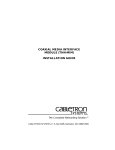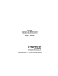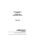
1
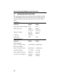
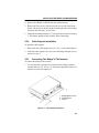
NB20E and NB25 E
TWO PORT ETHERNET BRIDGES
USER’S MANUAL
CABLETRON SYSTEMS, P.O. BOX 6257, ROCHESTER, NH 03867-6257
NOTICE
Cabletron Systems reserves the right to make changes in specifications
and other information contained in this document without prior notice.
The reader should in all cases consult Cabletron Systems to determine
whether any such changes have been made.
The hardware, firmware, or software described in this manual is subject to
change without notice.
IN NO EVENT SHALL CABLETRON SYSTEMS BE LIABLE FOR
ANY INCIDENTAL, INDIRECT, SPECIAL, OR CONSEQUENTIAL
DAMAGES WHATSOEVER (INCLUDING BUT NOT LIMITED TO
LOST PROFITS) ARISING OUT OF OR RELATED TO THIS
MANUAL OR THE INFORMATION CONTAINED IN IT, EVEN IF
CABLETRON SYSTEMS HAS BEEN ADVISED OF, KNOWN, OR
SHOULD HAVE KNOWN, THE POSSIBILITY OF SUCH DAMAGES.
© Copyright May 1990 by:
Cabletron Systems Inc.
P.O. Box 6257, E. Rochester, NH 03867-6257
All Rights Reserved
Printed in the United States of America
Order Number: 9030040-02 May 90
Remote LANVIEW, LANVIEW, NB25E, NB20E, and LAN-MD are
trademarks of Cabletron Systems Inc.
i
FCC NOTICE
FCC NOTICE
This device complies with Part 15 of the FCC rules. Operation is subject
to the following two conditions: (1) this device may not cause harmful
interference, and (2) this device must accept any interference received,
including interference that may cause undesired operation.
WARNING: This equipment uses and generates and can radiate radio
frequency energy and if not installed properly and used in accordance
with the instruction manual, may cause interference to radio
communications. It has been tested and found to comply with the limits
for a Class A digital device pursuant to Subpart J, of Part 15, of the FCC
rules., which are designed to provide reasonable protection against such
interference in a commercial environment. Operation of this equipment in
a residential area is likely to cause interference in which case the user at
his own expense will be required to correct the interference.
If this equipment does cause interference to radio or television, which can
be determined by turning the equipment off and on, the user is
encouraged to try to correct the interference by one or more of the
following measure:
•
•
•
•
Re-orient the receiving antenna.
Relocate the antenna with respect to the bridge.
Move the bridge away from the receiver.
Plug the bridge into a different outlet so that the bridge and the
receiver are on different branch circuits.
If necessary, the user should consult the dealer or an experienced radio/
television technician for additional suggestions. The user may find the
following booklet prepared by the Federal Communication Commission
helpful:
“How to Identify and Resolve Radio TV Interference Problems”
This booklet is available from the U.S. Government Printing Office,
Washington, D.C. 20401- Stock No. 004-000-00345-4
ii
CONTENTS
CHAPTER 1
INTRODUCTION
1.1 USING THIS MANUAL ................................................................ 1-1
1.2 GETTING HELP .......................................................................... 1-2
1.3 THE NB20E AND NB25E TWO PORT ETHERNET BRIDGE .... 1-2
1.4 THE BRIDGE FILTERING METHOD .......................................... 1-3
1.5 MULTIPLE BRIDGE ENVIRONMENTS ...................................... 1-5
1.5.1 The Root Bridge.............................................................. 1-5
1.5.2 Primary and Redundant Data Paths ............................... 1-6
1.6 REMOTE LANVIEW .................................................................... 1-7
1.7 RELATED MANUALS.................................................................. 1-8
CHAPTER 2
2.1
2.2
2.3
INSTALLATION REQUIREMENTS/
SPECIFICATIONS
LOCATION REQUIREMENTS .................................................... 2-1
NETWORK REQUIREMENTS .................................................... 2-1
OPERATING SPECIFICATIONS ................................................ 2-2
CHAPTER 3
INSTALLING THE NB20E OR NB25E BRIDGE
3.1 UNPACKING THE NB20E OR NB25E BRIDGE ......................... 3-1
3.2 INSTALLING THE BRIDGE......................................................... 3-1
3.2.1 Installing the Rack Mount Brackets ................................ 3-2
3.2.2 Cable Support Installation............................................... 3-3
3.2.3 Connecting The Bridge To The Network ........................ 3-3
3.2.4 Setting The Mode Switches ............................................ 3-4
3.2.5 Connecting The NB20E or NB25E To
The Power Source ......................................................... 3-5
CHAPTER 4
TESTING AND LANVIEW
4.1 INSTALLATION CHECK-OUT..................................................... 4-1
4.2 USING LANVIEW ........................................................................ 4-2
4.3 USING THE FORWARD BROADCAST SWITCH....................... 4-3
4.4 USING THE ROOT SWITCH ...................................................... 4-4
iii
CONTENTS
iv
CHAPTER 1
INTRODUCTION
Welcome to the Cabletron Systems NB20E™ and NB25E™ Two Port
Ethernet Bridges User's Manual. We have designed this user’s manual to
serve as a simple installation and reference guide for the NB20E and
NB25E, and to explain the capabilities and special features of each
individual bridge. With the appropriate design, the Cabletron Systems
NB25E or NB20E can dramatically improve network performance and
bandwidth efficiency on heavily utilized network segments.
You should read through this manual to gain a full understanding of the
NB20E and NB25E Bridges and their capabilities.
1.1
USING THIS MANUAL
Chapter 1, Introduction, discusses the capabilities of Cabletron Systems'
NB20E or NB25E Two Port Ethernet Bridge. An explanation of the
bridge filtering process and a discussion of bridge functionality in
multi-bridge environments are also included. The chapter concludes with
a list of related manuals.
Chapter 2, Installation Requirements/Specifications, contains a list of
hardware, software, location and environmental requirements that must be
met before you install either bridge.
Chapter 3, Installing the NB20E or NB25E Bridge, contains
instructions for installing the NB20E or the NB25E Two Port Ethernet
Bridge.
Chapter 4, Testing and Troubleshooting, provides procedures for testing
and troubleshooting the installation of the NB20E or the NB25E Bridge.
Instructions for using LANVIEW™, Cabletron Systems’ built-in visual
diagnostic and status monitoring system, are also included.
We assume that you have a general working knowledge of Ethernet or
IEEE 802.3 type data communications networks and their physical layer
components.
1-1
INTRODUCTION
1.2
GETTING HELP
If you need additional support related to the Cabletron Systems NB20E or
NB25E Two Port Ethernet Bridge, or if you have any questions,
comments or suggestions related to this manual, feel free to contact
Cabletron Systems' Technical Support at:
Cabletron Systems Inc.
P.O. Box 6257
E. Rochester, NH 03867-6257
Phone: (603) 332-9400
1.3
THE NB20E AND NB25E TWO PORT ETHERNET
BRIDGE
With the Cabletron Systems NB20E or NB25E Two Port Ethernet Bridge,
you can dramatically increase the performance of two 10 Mbit per second
Ethernet networks efficiently and economically, regardless of the media
type. The bridges are designed to increase the efficiency of bandwidth use
across a LAN by building a list of local node addresses as it learns which
nodes are located on each side of the bridge. This list is called the Source
Address Table. The bridge uses the Source Address Table to determine
which data packets should be allowed to cross the bridge, keeping local
traffic local.
The NB20E Bridge uses a software filter database to check destination
addresses against its Source Address Table. The NB25E Bridge uses a
higher performance hardware filter database. Both bridges are equipped
with a feature called Aging Time, that continually makes space for new
entries into the Source Address Table by deleting addresses that are not
frequently used.
The NB20E and NB25E are designed to function in multiple-bridge
environment. As IEEE 802.1 compliant bridging units, the bridges
incorporate a Spanning Tree Algorithm to detect potential data loops in
the network. Spanning Tree Algorithm is a hierarchy (or tree) of priorities
that is established between bridges.
The NB20E and NB25E can be controlled and managed by Cabletron
Systems' Remote LANVIEW™ - Network Control Management for the
Cabletron Systems' NB20E and NB25E. Remote LANVIEW provides the
most complete network management system for Ethernet networks in the
industry today. With Remote LANVIEW, a bridge can be managed
1-2
INTRODUCTION
according to the specific needs of a network manager. The network
manager's ability to set up parameters within Remote LANVIEW ensures
optimal performance for each bridge, and hence, each network. For
example, a network manager can manage and monitor: the flow of traffic
through a bridge, the status of a database, the bridge protocol and port
parameters, and the bridge setup.
Both bridges also incorporate Cabletron Systems' LANVIEW Status
Monitoring and Diagnostics Systems. Should a problem arise,
LANVIEW's LEDs will help you to diagnose problems, such as power
failures or cable faults. Individual or separate LEDs advise you that: the
bridge is on line and operational, the bridge is receiving or transmitting
data packets, or the bridge is detecting a collision signal from an
individual segment.
The NB20E or NB25E Bridge interconnects networks consisting of
Ethernet Version 1, Version 2, and/or IEEE 802.3 equipment. The bridge
has two AUI ports so it can be connected directly to any of Cabletron’s
many Ethernet transceivers for data transmission over various media
including twisted pair, fiber optic, and/or thick or thin Ethernet coaxial
cable.
1.4
THE BRIDGE FILTERING METHOD
The Cabletron Systems NB20E and NB25E prevent unnecessary network
traffic from passing through the bridge, by implementing a filtering
process. This process begins with the creation of a list of local node
addresses in a table referred to as the Source Address Table.
When the NB20E or NB25E first goes on line, the bridge initially
forwards all packets through the bridge. As the bridge receives a packet, it
learns the address of the sending node from the packet and stores that
address in its Source Address Table, indicating the segment on which the
address resides. In this manner, the bridge learns the address of each node
on each side of the bridge and is able to use the addresses stored in the
table to compare the destination address of each subsequent packet that
travels to the bridge. If the destination address of a packet is located on
the same segment (local segment) as the sending node, the packet is not
forwarded across the bridge.
Figure 1-1 provides an illustration of the filtering process.
1-3
INTRODUCTION
NODE A
NODE C
LAN 1
T
T
T
LAN 2
T
NODE B
Figure 1-1
Bridging Method
In this example, when Node A sends a packet to Node B, the bridge learns
Node A’s source address and adds the address to the Source Address
Table, indicating that the node is on LAN 1. If Node C subsequently sends
a packet to Node A, Node A’s address will be detected in the Source
Address Table for LAN 1 and the packet will not be forwarded across the
bridge to LAN 2. At the same time, the bridge will learn Node C’s source
address and add it to the Source Address Table, indicating that the node is
on LAN 1.
If the destination address of a packet is located on a different segment, the
bridge will forward the packet across the bridge. If Node B sends a packet
to Node A, the bridge will compare the destination address of the packet
against the addresses in the Source Address Table. It will then detect Node
A as being on the other side of the bridge and forward the packet through
the bridge to LAN 1. The bridge will store the address of Node B to
indicate that Node B is on LAN 2.
If no packets are sent from a source address in a five minute interval, that
address will be deleted from the bridge’s Source Address Table.
1-4
INTRODUCTION
This feature is referred to as Aging Time. Aging Time can be altered
through Cabletron Systems’ Remote LANVIEW Network Control
Management for the Cabletron Systems' NB20E and NB25E.
1.5
MULTIPLE BRIDGE ENVIRONMENTS
Both the NB20E and NB25E Two Port Bridges are designed to promote
maximum network use in multiple bridge environments. A bridge learns
the bridge topology of its network from bridge protocol data that is
transmitted onto the network by each bridge. The bridges then apply a
Spanning Tree Algorithm to select a root bridge and to determine primary
data paths within potential data loop configurations. A Spanning Tree
Algorithm, as defined earlier, is a hierarchy (or tree) of priorities that is
established between bridges. This hierarchy guarantees that primary and
redundant data paths will be clearly defined at all times, so that the
network is available to users at all times.
1.5.1
The Root Bridge
One bridge in the network is established as the root bridge. This bridge
has priority over all other bridges. Each bridge in a Spanning Tree must
learn which bridge is the root and then determine its own relative priority
within the network.
Determining the root bridge begins with the broadcast of Bridge Protocol
Data Units (BPDUs) across the network. When the bridges go on line,
each bridge sends out a BPDU which contains its priority field and its
unique identifier or Ethernet address. Through the broadcast of these
identifiers across the network, the bridges learn which bridge has the
highest priority, or lowest identifier. This bridge becomes the root bridge
for the network. Each bridge then determines its own priority in relation
to this bridge.
The network manager can, however, override this process for determining
the root. Using the root switch, the manager can manually select a
different bridge to be the root by applying a selectable switch at the
appropriate bridge. This bridge transmits BPDUs to inform the other
bridges that it is now the root. With this information, the bridges
immediately learn their new priority in relation to the new root, and the
system of priorities is maintained.
1-5
INTRODUCTION
1.5.2
Primary and Redundant Data Paths
To ensure the integrity of the network, primary data paths through
designated bridges, and redundant data paths through alternative bridges
are determined in each LAN or loop configuration in the network. A LAN
segment’s designated bridge is the bridge in a LAN or loop configuration
with the lowest cost path of transmission from that LAN segment to the
root bridge. The lowest cost path can be translated in a general way to
mean the data transmission path to the root that is most economical.
The bridges in the network send out BPDUs to the other bridges so that
they can all learn which is the bridge in the network, or in a potential loop
configuration, with the lowest cost path to the root. The bridges can then
determine their own priorities and roles as designated or redundant
bridges. Redundant bridges are “blocked” from forwarding packets, but
they continue to receive topology information.
Figure 1-2 provides a sample illustration of how a potential data loop is
prevented in a simple multibridge environment. A data loop exists
NODE A
T
T
BRIDGE 1
NB20E OR 25E
T
T
NB20E OR 25E
NB20E OR 25E
BRIDGE 2
BRIDGE 3
T
T
NODE B
Figure 1-2
1-6
Multiple Bridging Environments
INTRODUCTION
if all three bridges are on line and Node A sends a packet to Node B. The
packet will be forwarded through Bridges 1 and 3, and through Bridge 2,
causing the packet to be circulated many times around the data loop. If
Bridge 1 has priority over Bridge 2, the Spanning Tree Algorithm will
place Bridge 2 in blocking, preventing the packet from being forwarded
through Bridge 2. If Bridge 1 should fail, the Spanning Tree Algorithm
will be modified automatically so that the packet will be forwarded
through Bridge 2.
1.6
REMOTE LANVIEW
Both the NB20E and the NB25E can be controlled and managed by
Cabletron Systems' optional Remote LANVIEW - Network Control
Management for the Cabletron Systems' Bridges. Remote LANVIEW
allows you to control and manage multiple NB20Es or NB25Es from a
single Ethernet Workstation through Cabletron System NCM-DOS™ or
Remote LANVIEW/Windows™ or an individual NB25E through an
RS232 port on the bridge.
Remote LANVIEW provides the necessary management tools so that a
bridge can operate at its full capacity. The network manager's ability to set
up parameters within Remote LANVIEW ensures optimal performance
for each bridge, and, hence, each network. For example, a network
manager can monitor: the flow of traffic through a bridge, the status of a
database, the bridge protocol and port parameters, and the bridge setup.
The number of frames received at the bridge is recorded as well as a
breakdown of the progress through the bridge, for example the frames
discarded inbound or the frames forwarded outbound. A breakdown of
errors is provided so the network manager can pinpoint potential problem
areas in a network.
Bridge protocol and port parameters such as Topology Change,
Designated Root, and Path Cost are provided, so that the network
manager can keep track of bridge activity and cost. Certain parameters
can be altered to accommodate a network's particular requirements.
Remote LANVIEW provides the network manager with the necessary
control to operate a bridge effectively. For instance, a network manager
can alter bridge setup, erase a database, disable or restart a bridge, reset
counters, or restore default settings.
1-7
INTRODUCTION
For further information for refer to the Remote LANVIEW - Network
Control Management for the Cabletron Systems' NB20E and NB25E
User's Manual.
1.7
RELATED MANUALS
The manuals listed below should be used to supplement the procedures
and other technical data provided in this manual. The procedures will be
referenced where appropriate, but will not be repeated.
Cabletron Systems' Remote LANVIEW - Network Control
Management for the Cabletron Systems' NB20E and NB25E User’s
Manual.
Cabletron Systems' LAN-MD User’s Manual.
1-8
CHAPTER 2
INSTALLATION REQUIREMENTS/
SPECIFICATIONS
Before you attempt to install Cabletron Systems' NB20E or NB25E Two
Port Ethernet Bridge, review the location and hardware requirements
outlined in this chapter. Also refer to the operating specifications and
environmental requirements that are listed.
All conditions, guidelines, specifications and requirements included in
this chapter must be met to ensure satisfactory performance of the NB20E
or NB25E. Failure to follow these guidelines will result in unsatisfactory
network performance.
2.1
LOCATION REQUIREMENTS
Before installing the NB20E or NB25E Two Port Ethernet Bridge, ensure
that the location for the bridge meets the following requirements:
•
The location must have an unrestricted surface area 21 inches (53.34
cm) wide, and must be at least 18 inches (45.72 cm) deep and 6 inches
(15.24 cm) high.
•
A standard 3 prong power receptacle must be located within 7 feet
(2.13 m) of the site.
•
If a shelving unit is to be used, the unit must be able to support 30
pounds (13.6 kg) of static weight.
•
The temperature of the location must be maintained between 5° and
40°C. Temperature changes of greater than 10°C per hour must not
occur.
2.2
NETWORK REQUIREMENTS
When bridging two segments using an NB20E or NB25E Two Port
Bridge, you must follow the network guidelines listed below:
•
The transceivers to which the NB20E or NB25E will be connected
must meet Ethernet Version 1, Version 2, or IEEE 802.3 standards.
•
The AUI cables connecting the NB20E or NB25E to the transceivers
on the network must be IEEE 802.3 type cables and must not exceed
50 meters in length.
2-1
INSTALLATION REQUIREMENTS/ SPECIFICATIONS
2.3
OPERATING SPECIFICATIONS
The operating specifications for Cabletron Systems' NB20E or NB25E
Two Port Bridge Series are included in this section. Cabletron Systems
reserves the right to change these specifications at any time without
notice.
GENERAL
Parameter
NB20E
NB25E
Packet Buffer Memory (RAM): 128K
128K
Internal Processor:
16MHz
Intel 80186
16MHz
Intel 80186
Ethernet Controller:
two 8390
Ethernet
Controllers
two 8390
Ethernet
Controllers
Scratch Ram:
512K
512K
Parameter
NB20E
NB25E
Packet Filter Rate
(max. viewed per second):
15,000 Packets 28,000 Packets
Packet Forward Rate
(max. viewed per second):
8,000 Packets
11,000 Packets
Forwarding Latency:
125 µs Min.
91 µs Min.
Source Address Table Size:
2048 Max.
8191 Max.
Age Time (User Definable):
5 Minutes
(Default)
5 Minutes
(Default)
PERFORMANCE
2-2
INSTALLATION REQUIREMENTS/ SPECIFICATIONS
FRONT PANEL INDICATORS
ON LINE
When lit, this LED indicates the two port
bridge is on line and operational (green
indicator).
STAND BY
When lit, this LED indicates the bridge is not
forwarding packets (yellow indicator).
NOTE: There is one TRANSMIT, RECEIVE, COLLISION, and POK
(Port OK) LED for each segment. The LEDs for RECEIVE, TRANSMIT
and COLLISION are pulsed-stretched for increased viewing effect.
XMT (transmit)
When lit, this LED indicates the bridge is
transmitting packets to that segment (green
indictor).
RCV (receive)
When lit, this LED indicates that the bridge
is receiving data packets from that segment
(yellow indicator).
CP (collision present)
When lit, this LED indicates that a collision
is occurring on that segment (red indicator).
POK (port ok)
When lit, this LED indicates transceiver
connected, port has passed Loop Back Test
and is ready for transmission (green
indicator).
FRONT PANEL SWITCHES
FORWARD BROADCAST | / O When this switch is on (|), it allows the
bridge to forward broadcast messages.
2-3
INSTALLATION REQUIREMENTS/ SPECIFICATIONS
FRONT PANEL SWITCHES (cont.)
ROOT | / O
When the switch is on ( | ), it designates the
bridge as the root bridge in the network.
AUI PORT (NB20E/NB25E)
Interface Connector
Type:
15 position D type receptacle.
Pin 1 Logic Ref.
Pin 9 Collision -
2 Collision +
10 Transmit -
3 Transmit +
11 Logic Ref.
4 Logic Ref.
12 Receive -
5 Receive +
13 Power (+12 Vdc)
6 Power return
14 Logic Ref.
7 No Connection
15 No Connection
8 Logic Ref
Connector Shell:
Protective Ground
RS232 PORT
Type:
Standard 9 pin RS232 Port
Pin 1 DCD
Pin 6 NU
2 TX
7 TRS
3 RX
8 CTS
4 DTR
9 RX Clock
5 Signal Ground
2-4
INSTALLATION REQUIREMENTS/ SPECIFICATIONS
POWER SUPPLY REQUIREMENTS
Parameter
Typical
Value
Worst
Case
120V Input Voltage: 120 V
90 to 130 V
Input Current
NB20E:
NB25E:
Frequency Range:
0.5 Amps
0.75 Amps
1.0 Amps
1.5 Amps
47 - 63 Hz
220V Input Voltage: 220 V
180 to 264 V
Input Current
NB20E:
NB25E:
Frequency Range:
0.25 Amps
0.375 Amps
0.5 Amps
0.75 Amps
47 - 63 Hz
Overload Protection
Input:
(2) 3AG 3 amp fuses in series with both primary
inputs.
Output:
(2) 3AG 1 amp fuse for each AUI port.
ENVIRONMENTAL REQUIREMENTS
Operating Temperature:
+5° to +40°C
Non-operating Temperature: -30° to +90°C
Operating Humidity:
5 to 95% (non-condensing)
2-5
INSTALLATION REQUIREMENTS/ SPECIFICATIONS
SAFETY
Designed in accordance with UL478, UL910, NEC 725-2(b), CSA, IEC,
TUV, VDE class A. Meets FCC part 15, Subparagraph J, Class A limits.
WARNING: It is the responsibility of the person who sells the system of
which the NB20E or NB25E will be a part to ensure that the total system
meets allowed limits of conducted and radiated emissions.
SERVICE
MTBF (MHBK - 20E):
NB20E:
> 35,750 hrs. projected.
NB25E:
> 26,533 hrs. projected.
MTTR:
< 0.5 hrs.
PHYSICAL PROPERTIES
Dimensions:
3.2H x 17.0W x 12.4D inches
(8.13 x 38.1 x 31.5 cm)
Weight
Unit:
Shipping:
2-6
7 lbs. (3.17 kg.)
8 lbs. (3.63 kg.)
CHAPTER 3
INSTALLING THE NB20E OR NB25E BRIDGE
This section contains instructions for installing Cabletron Systems'
NB20E or NB25E Two Port Ethernet Bridge, and for preparing the bridge
for operation. Verify that all network design guidelines and site
requirements listed in Chapter 2, Installation Requirements/
Specifications, are met before installing the bridge.
3.1
UNPACKING THE NB20E OR NB25E BRIDGE
Before you install the NB20E or NB25E Bridge, you should visually
inspect the bridge and check the contents of the accessory package. To
unpack the bridge and accessory package:
1. Carefully remove the bridge from the shipping box. Save the shipping
box and materials in the event the unit has to be reshipped.
2. Slide the two foam end caps off of the bridge and remove the bridge
from its protective plastic bag. Set the bridge aside to prevent the unit
from being damaged.
3. Remove the plastic bag containing the accessory package and check
that the bag contains the following items:
•
•
•
•
•
one 8 foot (2.44 m) power cord
one cable support bracket
two 8-32 x .375 inch screws
three 6 (15.24 cm) inch cable ties
rack mount brackets
Contact Cabletron Systems' Technical Support immediately if any
discrepancy in materials exists.
3.2
INSTALLING THE BRIDGE
After you have met all requirements listed in Chapter 2, Installation
Requirements, complete the installation instructions provided in this
section.
3-1
INSTALLING THE NB20E OR NB25E BRIDGE
3.2.1
Installing the Rack Mount Brackets
If the NB20E or NB25E will be rack mounted:
1. Remove the four screws (5, Fig. 3-1) holding the four rubber feet to
the bridge. This frees the top plastic housing (1) from the bridge.
2. Carefully remove the top plastic housing.
3. Remove the four screws (6) holding the bottom plastic housing (4) to
the bridge’s chassis.
1.
2.
3.
4.
Top Housing
Screws (4)
Rack Mount Bracket
Bottom Plastic Housing
Figure 3-1
3-2
5.
6.
7.
Screws (4)
Screws (4)
Rack Mount Bracket
Rack Mount Brackets Installation
INSTALLING THE NB20E OR NB25E BRIDGE
4. Remove the NB20E or NB25E from the bottom housing.
5. Remove the four screws (2) that secure the cover to the front of the
bridge. The screws are located on the left and right sides of the bridge
(closest to the front side), two per side.
6. Attach the rack mount brackets (3, 7) using the screws removed in step
5. The bracket should be flush with the front of the bridge.
3.2.2
Cable Support Installation
To install the cable support:
1. Remove the four cable support screws (3, Fig. 3-2) from the bridge (1).
2. Attach the cable support (2) to the rear of the bridge using the screws
removed in step 1.
3.2.3
Connecting The Bridge To The Network
To connect the bridge to the network:
1. For each network segment to be connected to the bridge, attach an
external transceiver (1, 9, Fig. 3-3). Refer to the applicable transceiver
manual to connect the transceiver.
1. Bridge (NB25 Shown)
2. Cable Support
3. Screws
Figure 3-2
Cable Support Installation
3-3
INSTALLING THE NB20E OR NB25E BRIDGE
1
9
10
8
2
7
3
1.
2.
3.
4.
5.
4
ST-500 Transceiver
AUI Cable
Bridge
AUI Port 2
AUI Port 1
Figure 3-3
5
6.
7.
8.
9.
10.
6
Power Receptacle
Power Cord
AUI Cable
ST-500 Transceiver
RS232 Port (NB25E only)
Installation
2. Attach an AUI cable (2, 8) no more than 50 meters in length to each of
the transceivers that you connected to each network segment.
3. Connect the AUI cable from the transceiver to the AUI port (4, 5)
located on the back panel of the NB20E or NB25E bridge.
3.2.4
Setting The Mode Switches
Before connecting the bridge to the power supply, set the Forward
Broadcast and Root switches to the appropriate On (|) or
Off (O) position as defined below:
•
If you want the bridge to pass Broadcast messages between segments,
set the FORWARD BROADCAST switch (Fig. 3-4) to the On (|)
position.
•
If you want this bridge to receive priority over all other bridges on the
network, set the ROOT switch (Fig. 3-4) to the On (|) position. Only
ONE bridge on the network should have the ROOT switch enabled.
3-4
INSTALLING THE NB20E OR NB25E BRIDGE
NB-25E
XMT
ON LINE
ETHERNET /IEEE 802.3 BRIDGING UNIT
WITH REMOTE LANVIEW® AND MANAGEMENT
RCV
STAND BY
FORWARD
BROADCAST
1
0
ROOT
1
0
CP
POK
1
Figure 3-4
3.2.5
PORT
2
Bridge Front Panel
Connecting The NB20E or NB25E To The Power
Source
When installation of the NB20E/NB25E Bridge is complete and the
switches have been set, connect the bridge to the power source in the
following manner:
1. If you have not already done so, plug the power cord (7, Fig. 3-3) into
the power receptacle (6) located on the rear panel of the bridge.
2. Plug the power cord into a wall receptacle.
3. Turn the power switch, located next to the power receptacle, to the on
position.
4. Observe the status of the ON-LINE, STANDBY, PORT 1 OK and
PORT 2 OK LEDs. These LEDs will flash for approximately 10
seconds as the bridge performs it's internal diagnostics.
When the bridge finishes its internal diagnostics, the LEDs should be
in the following conditions:
•
ON LINE LED lit, indicating that the bridge is receiving power.
•
PORT 1 OK and PORT 2 OK lit, indicating that the ports have
passed the internal loopback test and are now ready for
transmission.
•
STANDBY on or off, depending on the bridge's position in the
Spanning Tree Algorithim.
3-5
INSTALLING THE NB20E OR NB25E BRIDGE
The following conditions indicate a problem has been detected with
the bridge:
•
The ON-LINE, STANDBY, PORT 1 OK and PORT 2 OK LEDs
do not start to flash on power up, indicating that the Real Time
Clock has failed.
•
The ON-LINE, STANDBY, PORT 1 OK and PORT 2 OK LEDs
do not stop flashing after power up, indicating that the Network
Interface Chip has not been properly initialized.
•
A PORT OK LED is not lit, indicating that the port failed the
loopback test and that the Network Interface Chip for that port
failed.
If any of these conditions exist, contact Cabletron Systems Technical
Support.
When power connection is complete, use the cable ties that are provided
to strain-relief all cables to the cable support (2, Fig. 3-2) to relieve
unnecessary pressure at cable connection points.
The NB20E or NB25E Bridge is now ready for operation. Before
transmitting data, test the installation. For this procedure, refer to the
section, Chapter 4, Testing and LANVIEW.
3-6
CHAPTER 4
TESTING AND LANVIEW
This section contains procedures to test the NB20E or NB25E Two Port
Ethernet Bridge after it has been connected to the network. A description
of the LANVIEW LEDs, the Forward Broadcast, and the Root Switch, is
also provided.
4.1
INSTALLATION CHECK-OUT
After the NB20E or NB25E is connected to the network, verify that
packets can be passed between the two Ethernet network segments via the
bridge. Two Ethernet node testers, such as Cabletron Systems'
LAN-MD™, are required for this procedure to generate valid data
packets.
Before you begin, test each Ethernet segment connected to the NB20E or
NB25E to ensure that the segments meet IEEE 802.3 specification limits.
1. Move the Forward Broadcast switch on the front panel of the Bridge
(Fig. 4-1) to the On (|) position. This will allow broadcast messages
sent by the LAN-MDs to pass through the bridge.
2. Using a transceiver (1, Fig. 4-2) and an AUI cable, connect a
LAN-MD (2) to one of the segments connected to the bridge (3).
3. Select and run test 6 - SERVER on this LAN-MD.
4. Verify that the Test Status PASS LED is lit and that the Status Code
reads 000 or 001. If these two conditions are met, the LAN-MD is now
the SERVER unit and will act as a packet echoer when used with
another LAN-MD.
NB-25E
XMT
ON LINE
ETHERNET /IEEE 802.3 BRIDGING UNIT
WITH REMOTE LANVIEW® AND MANAGEMENT
RCV
STAND BY
FORWARD
BROADCAST
1
0
ROOT
1
0
CP
POK
1
Figure 4-1
PORT
2
LANVIEW LEDs
4-1
TESTING AND LANVIEW
5. Using a transceiver (5) and an AUI cable, connect another LAN-MD
(4) to the other segment connected to the bridge.
6. Select and run test 4 - NODE on the LAN-MD connected in the
previous step.
7. Verify that this test passes. At least 100 packets should be sent and
received by the bridge, with no errors. Packets will be sent from this
LAN-MD to the other LAN-MD, acting as the Server, then echoed
back.
When the NB20E or NB25E have successfully completed these tests, the
bridge is ready for normal operation. If any failures were noted, please
contact Cabletron Systems' Technical Support.
4.2
USING LANVIEW
The NB20E and NB25E Two Port Ethernet Bridges use Cabletron
Systems' built-in visual diagnostic and status monitoring system called
LANVIEW. With LANVIEW, network troubleshooting personnel can
quickly scan LANVIEW's LEDs to observe network status, or diagnose
network problems. Figure 4-1 displays the LANVIEW LEDs on the
NB20E and NB25E.
Seg. A
Seg. B
1
5
3
2
1. ST-500
2. LAN-MD
3. NB 20E/25E
4. LAN-MD
5. ST-500 Transceiver
Figure 4-2
4-2
Check Out Configuration
4
TESTING AND LANVIEW
ON LINE LED
When this green LED is lit, the bridge is on line and operational. The unit
has completed a self diagnostics test and is capable of forwarding packets.
STAND BY LED
When this yellow LED is lit, the bridge is in the “Stand by” mode and not
capable of forwarding packets.
NOTE: There are separate XMT, RCV, CP, and POK LEDs for each port
on the NB20E and NB25E.
TRANSMIT (XMT) LED
When this green LED is flashing, the bridge is transmitting packets to that
network segment.
RECEIVE (RCV) LED
When this yellow LED is flashing, bridge is receiving a data packet from
that segment.
COLLISION PRESENT (CP) LED
When this red LED is flashing, a collision is occurring on that segment.
PORT OK (POK) LED
This green LED is lit to indicate that the transceiver is connected, and that
the port has passed an internal Loop Back Test and is ready for
transmission.
4.3
USING THE FORWARD BROADCAST SWITCH
The Forward Broadcast switch, Figure 4-1, allows the user to select
whether the bridge will forward broadcast messages from one network
segment to the other. When the switch is in the On (|) position, the bridge
will allow broadcast messages to pass.
4-3
TESTING AND LANVIEW
4.4
USING THE ROOT SWITCH
In a multiple-bridge environment, the Root switch, Figure 4-1, for a
particular bridge allows the user to set that bridge as the root bridge. Only
one bridge can serve as the root bridge in a multiple bridge environment,
however. In the event that two bridges have been selected as root bridges,
the bridge in the environment with the lowest identifier will become the
root bridge.
4-4