1
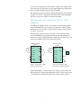
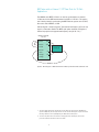
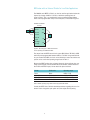
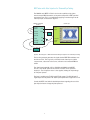
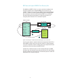
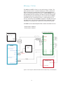
Agilent
Application Block Diagrams for 10 Gb/s
BERT Test Systems
Application Note
Agilent designs and manufactures a collection of low-cost instruments and
test accessories, including a 10 Gb/s BERT for 0.5 to 12.5 Gb/s applications.
The N4962A serial BERT 12.5 Gb/s can be used for a collection of signal
integrity applications as listed below.
Each application is discussed in detail with block diagrams in this document.
For more information, please contact www.agilent.com/find/contactus
1. Pattern generator for use with oscilloscope
2. BER tester for use with a simple electrical DUT for 10 Gb/s
applications
N4962A serial BERT
12.5 Gb/s
TX CKI
RX CKI
RX CKO
~OUT
TX CKO
EXT CKI
JitterI
HF TrigO
LF TrigO
3. BER tester with an external 1/16th rate clock for 10 Gb/s
applications
OUT
IN
~IN
DUT
4. BER tester with an external divider for low-rate applications
5. BER tester with an external full-rate clock for 0.5 to 12G
applications
6. BER tester with jitter injection for stressed eye testing
7. BER tester with Agilent N4982A clock recovery unit BER testing
>12.5 Gb/s
Pattern Generator for Use with Oscilloscope
The N4962A serial BERT 12.5 Gb/s can be used as a high-performance GPIBprogrammable PRBS (pseudo-random bit sequence) generator. This application
is ideally suited for measuring the eye performance of the DUT, including ‘eye
mask’ measurements.
A simple PRBS generator block diagram is shown in Figure 1; this setup is used
to characterize the output performance of the BERT. The two small coaxial loops
are shown connecting the BERT clock outputs to the clock inputs. The LF TrigO
(615 to 709 MHz) output is connected to the scope trigger input.
Oscilloscope
N4962A serial BERT
12.5 Gb/s
TX CKI
RX CKI
RX CKO
Data
input
OUT
~OUT
TX CKO
EXT CKI
JitterI
HF TrigO
LF TrigO
IN
Trigger
input
~IN
Figure 1. Block diagram – performance verification with oscilloscope
Once the BERT output has been characterized with rise/fall times, RMS and p-p
jitter, output amplitude, eye height, signal-to-noise ratio, etc, a common application is to measure the performance of a DUT, shown in Figure 2.
Oscilloscope
N4962A serial BERT
12.5 Gb/s
TX CKI
RX CKI
RX CKO
DUT
OUT
Data
input
~OUT
TX CKO
EXT CKI
JitterI
HF TrigO
LF TrigO
IN
Precision
Trigger
input
~IN
Figure 2. Block diagram – DUT eye-mask measurement with oscilloscope
2
In this case, we are using the ‘precision timebase’, a high-precision trigger input on
the oscilloscope. This scope input can accept a higher frequency rate trigger signal,
and is connected to HF TrigO (a full-rate clock) on the BERT.
Even though we are using a more precise method of triggering the oscilloscope, the
performance of the DUT is slowing down the transition times and increasing RMS
jitter. The scope is shown making an ‘eye-mask’ measurement.
BER Tester for Use with a Simple Electrical DUT for 10 Gb/s
Applications
The N4962A serial BERT 12.5 Gb/s can be used as a high-performance GPIBprogrammable BERT (bit error rate tester). This application is ideally suited for
measuring the errors caused by an electrical DUT operating at 10 Gb/s (9.85 to
11.35 Gb/s, to be exact).
A block diagram is shown in Figure 3; this setup is used to verify the performance of the BERT. By connecting the OUT directly to the IN, the BERT will
measure the amount of signal degradation introduced by the coaxial cable – this
should result in BER=0 at most phase adjustment settings.
N4962A serial BERT
12.5 Gb/s
TX CKI
RX CKI
RX CKO
N4962A serial BERT
12.5 Gb/s
TX CKI
RX CKI
OUT
~OUT
RX CKO
TX CKO
EXT CKI
JitterI
HF TrigO
LF TrigO
OUT
~OUT
TX CKO
EXT CKI
IN
JitterI
~IN
HF TrigO
LF TrigO
Figure 3. Block diagram – BERT
verification measurement
DUT
IN
~IN
Figure 4. Block diagram – BER
measurement of single-ended DUT
Another block diagram is shown in Figure 4; this setup is used to measure the
BER introduced by a simple single-ended electrical DUT. The two cables used to
connect the DUT to the output and input do not need to be phase-matched.
3
BER Tester with an External 1/16th Rate Clock for 10 Gb/s
Applications
The N4962A serial BERT 12.5 Gb/s can also be synchronized to an external
1/16th rate clock for BER measurements from 9.85 to 11.35 Gb/s. This application is ideally suited for synchronizing the BERT with the system clock of a DUT,
like a transceiver, SERDES, or CDR.
A block diagram is shown in Figure 5. The external low-frequency (LF, clock/16)
signal is connected to ExtCKI. The BERT synth option should be changed to 0,
and the freq option to the approximate frequency rate (clk/16 * 16). 1, 2
N4962A serial BERT
12.5 Gb/s
TX CKI
RX CKI
RX CKO
OUT
~OUT
TX CKO
EXT CKI
JitterI
HF TrigO
LF TrigO
DUT clk/16
IN
~IN
Figure 5. Block diagram – BER measurement of DUT synchronized with 1/16th rate clock
1. The clock signal applied to the ExtCKI port must be within the range of 615 to 709 MHz; this
signal is multiplied by 16 and output from the TX CKO and RX CKO outputs. Frequencies outside
this range will not be correctly multiplied by the BERT internal clock system.
2. To ensure the phase lock of an external LF clock applied to the ExtCKI port, reference the
procedure detailed in Section 2.2 of the User Guide.
4
BER tester with an External Divider for Low-Rate Applications
The N4962A serial BERT 12.5 Gb/s can also be used for applications below the
internal clock range of 9.85 to 11.35 Gb/s, within the operating limits of
0.5 to 12.5 Gb/s. This is accomplished by using an external divider (Agilent
offers several programmable units) in the clock path, as illustrated in Figure 6.
N4962A serial BERT
12.5 Gb/s
÷N
÷N
TX CKI
RX CKI
RX CKO
OUT
~OUT
TX CKO
EXT CKI
JitterI
HF TrigO
LF TrigO
DUT
IN
~IN
Figure 6. Block diagram – BER measurement
of low operating rate differential DUT
The output from the BERT internal clock system (RX CKO and TX CKO) is GPIB
and front-panel programmable between 9.85 to 11.35 GHz. Using external dividers, part number UXC20PE, the clock can be divided to a lower rate and the test
system can be used in the operating ranges listed in Table 1.
Because the BERT receiver has an internal electronic phase-adjuster, the coax
cables connecting the TX CKO and RX CKO to the dividers, and the dividers to
the TX CKI and RX CKI inputs, do not need to be phase matched.
Divider
Divide ratio
Operating range
None
None
9.85 to 11.35
UXC20PE
Divide-by-2
4.925 to 5.675
UXC20PE
Divide-by-4
2.4625 to 2.8375
UXC20PE
Divide-by-8
1.23125 to 1.41875
Table 1. BERT operating range with external programmable divider
Consult the BERT Users’ Guide for detailed procedures regarding the use of an
external clock: change the synth option to 0, then adjust the freq setting.
5
BER Tester with an External Full-Rate Clock for 0.5 to 12.5 Gb/s
Applications
The N4962A serial BERT 12.5 Gb/s can also be used for applications within a
full range of operating rates from 500 Mb/s to 12.5 Gb/s. This is accomplished
by applying an external clock signal to the BERT clock inputs, RX CKI and TX
CKI, as illustrated in Figure 7.
N4962A serial BERT
12.5 Gb/s
TX CKI
RX CKI
Power
splitter
RX CKO
~OUT
TX CKO
EXT CKI
OUT, +10 dBm
clock
synthesizer
OUT
JitterI
HF TrigO
LF TrigO
DUT
IN
~IN
Figure 7. Block diagram – multi-rate BER
measurement of DUT with external clock
Because the BERT receiver has an internal electronic phase-adjuster, the
coaxial cables connecting the power splitter to the TX CKI and RX CKI inputs do
not need to be phase matched.
The clock input (TX CKI and RX CKI) power input requirements are typically
+4 dBm, so the synthesizer should generate more than a +7 dBm output if a
power splitter is used.
Consult the BERT Users’ Guide for detailed procedures regarding the use of
an external clock: change the synth option to 0, adjust the freq setting to the
approximate frequency rate.
6
BER Tester with Jitter Injection for Stressed Eye Testing
The N4962A serial BERT 12.5 Gb/s also has the capability to inject jitter
onto the output PRBS datastream; an important component of IEEE-specified
stressed eye tests. This is accomplished by applying an external signal to the
JitterI input port as illustrated in Figure 8.
Oscilloscope
N4962A serial BERT
12.5 Gb/s
TX CKI
RX CKI
RX CKO
Data
input
OUT
~OUT
DUT
TX CKO
EXT CKI
JitterI
HF TrigO
LF TrigO
IN
Precision
trigger
input
~IN
Function
generator
Figure 8. Block diagram – BER measurement with jitter injection for stressed eye testing
The function generator generates the signal that the BERT FM modulates onto
the full-rate clock. This is typically a sinusoid, but the JitterI input could be
a square wave, a Gaussian noise source, and even an uncorrelated PRBS bit
stream.
The JitterI input bandwidth is DC to 100 MHz; the N4962A serial BERT
12.5 Gb/s User Guide spells out the amount of UI that can be injected in
Section 2.2. The UI injection vector is also supplied, relating the input voltage
to UI of jitter injected.
The jitter is applied to the TX CKO and HF TrigO outputs. The RX CKO and LF
TrigO outputs are not jittered. The JitterI input requirements range from 0 to 2 V.
Consult the BERT User Guide for detailed procedures regarding the use of the
jitter injection feature: change the jitter option to 1.
7
BER Tester with Agilent N4982A Clock Recovery Unit
The N4962A serial BERT 12.5 Gb/s can also be used with a broadband clock
recovery unit, like the low-cost Agilent N4982A clock recovery unit. This
“AnyRate” CRU will recover a clock from a PRBS bit stream from 622 Mb/s to
13.5 Gb/s—perfect for use with the wide operating range of the Agilent BERT.
By recovering the clock from the DUT output, the BERT can accommodate
tests where polarization mode dispersion (or other physical effects) can
change the period of the data. This is illustrated in Figure 9.
N4962A serial BERT
12.5 Gb/s
TX CKI
RX CKI
RX CKO
DUT with PMD
E/O
OUT
~OUT
TX CKO
N4982A CRU
EXT CKI
JitterI
HF TrigO
LF TrigO
O/E
Out
IN
In
Splitter
~IN
Out
Data input
CLK output
~CLK output
Figure 9. Block diagram – BER measurement with Agilent clock recovery unit
A passive power splitter is required to duplicate the output signal of the DUT to
feed the BERT and CRU input. If the output from the DUT is severely degraded
or very low in amplitude, a buffer or retiming stage may be required to boost the
amplitude to meet the sensitivity of the BERT and CRU.
If the DUT has a differential output, one side should be delivered to the BERT
IN, and the other side should be connected to the CRU input. This will eliminate
the power splitter from the block diagram, and will allow operation at lower DUT
output levels. This is shown in Figure 10.
8
N4962A serial BERT
12.5 Gb/s
TX CKI
RX CKI
RX CKO
DUT with PMD
OUT
~OUT
E/O
O/E
TX CKO
EXT CKI
JitterI
HF TrigO
LF TrigO
IN
Data input
~IN
CLK output
~CLK output
N4982A CRU
Figure 10. Block diagram – Differential BER measurement with Agilent CRU
The N4982A clock recovery unit will automatically scan between 622 Mb/s and
13.5 Gb/s, and will lock onto the highest-power frequency rate it can find. The
recovered clock is ideally suited to drive the BERT error detector.
Consult the CRU User Guide for detailed procedures regarding the use of the
clock recovery unit.
9
BER testing >12.5 Gb/s
The N4962A serial BERT 12.5 Gb/s can be used for testing > 12.5 Gb/s. The
pattern generator section is capable of operating up to 15 Gb/s, but the error
detector section does not operate above 12.5 Gb/s. However BER measurements can be made above 12.5 Gb/s by using a 1:2 DeMux (N4968A clock and
data demultiplexer 44 Gb/s) before the error detector input and checking both
de-multiplexed data signals independently. In the example below the N4962A
serial BERT 12.5 Gb/s is operating at 14.2 Gb/s—pattern generator runs at
14.2 Gb/s into DUT then into the N4968A configured as 1:2 DeMux, then to the
error detector at 7.1 Gb/s(two data streams Data Out1 and Data Out3, tested
individually). The sampling scope is optional but can help with timing setup.
The N4968A clock and data demultiplexer 44 Gb/s internal clock dividers are set to:
• Divider #1, #2 - divide by 2
• Divider #3, #4 - divide by 1
Clock and data demultiplexer
Signal generator
Splitter
10G BERT
DUT
Sampling scope
Figure 11. Block diagram – BER measurements above 12.5 Gb/s using a 1:2 demultiplexer
10
Setup Instructions
1. Use an external RF signal generator and a 6 dB power splitter to send the
clock signal to both the N4962A serial BERT 12.5 GB/Sand the N4968A
clock and data demultiplexer 44 Gb/s.
2. Bypass the N4962A serial BERT 12.5 Gb/s internal clock path, and connect
the clock signal directly to the pattern generator section clock input TX CKI.
A level of +4 dBm at TX CKI should be sufficient. Also connect the N4968A
clock and data demultiplexer 44 Gb/s clock output directly to the error
detector section clock input RX CKI.
3. May have to increase the clock power to the N4962A serial BERT 12.5 Gb/s
pattern generator to get a clean, error free eye, but be careful not to exceed
the clock Input 1 level to the N4968A clock and data demultiplexer 44 Gb/s
which is about +4 dBm—may want to add an additional attenuator in line,
6 dB should be sufficient.
4. Data input signal to the N4968A clock and data demultiplexer 44 Gb/s must
be ac-coupled 1.0Vpp or swing about 0V. A dc block is recommended at the
input.
5. Terminate all unused inputs & outputs with 50 Ω loads.
6. Aligning the 14.2G clock and data. Once connected up, adjust the N4968A
clock and data demultiplexer 44 Gb/s phase shifter to align the clock and
data inputs to the 1:2 demux for error free operation. Do this by monitoring
the N4962A serial BERT 12.5 Gb/s BER error light, and also noting the time
position of the Data Out4 eye crossing on the scope.
NOTE: Make sure the N4962A serial BERT 12.5 Gb/s receiver is OFF at this stage, ignore any
BER reading on the display, monitor only the status of the error light. First adjust the N4968A
clock and data demultiplexer 44 Gb/s phase shifter until the N4962A serial BERT 12.5 Gb/s
error light changes from off to on; note the time position of the eye crossing on the scope. Then
move the phase shifter in the opposite direction until it the error light again changes from off to
on; note again the time position of the eye crossing on the scope. Then adjust the phase shifter
one more time to position the eye crossing midway between the two previously noted values.
The 14.2 GHz clock should now be optimally aligned with the 14.2 Gb/s data at the N4968A
clock and data demultiplexer 44 Gb/s 1:2 demux.
7. Aligning the 7.1G clock and data. Next optimize the clock and data phase at
the N4962A serial BERT 12.5 Gb/s error detector input by using the autophase feature within the N4962A serial BERT 12.5 Gb/s
Ensure the Receiver►On is not selected (the error detector must be off
Press the Display►Scroll || button and select Ø
Press the Adjust►Config State + button to auto-select the detector phase
Observe the Error ε light (should remain off, indicating no errors detected)
8. For fine tuning reiterate steps 6 and 7.
9. Turn on the N4962A serial BERT 12.5 Gb/s receiver to perform a BER
measurement.
11
www.agilent.com
www.agilent.com/find/BERT
Agilent Email Updates
www.agilent.com/find/emailupdates
Get the latest information on the
products and applications you select.
Agilent Channel Partners
www.agilent.com/find/channelpartners
Get the best of both worlds: Agilent’s
measurement expertise and product
breadth, combined with channel
partner convenience.
Agilent Advantage Services is committed
to your success throughout your equipment’s lifetime. To keep you competitive,
we continually invest in tools and
processes that speed up calibration and
repair and reduce your cost of ownership.
You can also use Infoline Web Services
to manage equipment and services more
effectively. By sharing our measurement
and service expertise, we help you create
the products that change our world.
www.agilent.com/find/advantageservices
For more information on Agilent
Technologies’ products, applications or
services, please contact your local Agilent
office. The complete list is available at:
www.agilent.com/find/contactus
Americas
Canada
Brazil Mexico
United States
(877) 894 4414
(11) 4197 3600
01800 5064 800
(800) 829 4444
Asia Pacific
Australia 1 800 629 485
China
800 810 0189
Hong Kong 800 938 693
India 1 800 112 929
Japan
0120 (421) 345
Korea
080 769 0800
Malaysia 1 800 888 848
Singapore 1 800 375 8100
Taiwan
0800 047 866
Other AP Countries (65) 375 8100
Europe & Middle East
Belgium 32 (0) 2 404 93 40
Denmark
45 45 80 12 15
Finland
358 (0) 10 855 2100
France
0825 010 700*
*0.125 €/minute
Germany
49 (0) 7031 464 6333
Ireland
1890 924 204
Israel972-3-9288-504/544
Italy
39 02 92 60 8484
Netherlands
31 (0) 20 547 2111
Spain
34 (91) 631 3300
Sweden
0200-88 22 55
United Kingdom 44 (0) 118 927 6201
For other unlisted countries:
www.agilent.com/find/contactus
Revised: January 6, 2012
Product specifications and descriptions
in this document subject to change
without notice.
© Agilent, Inc. 2012
Published in USA, July 17, 2012
5991-0602EN