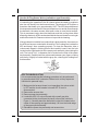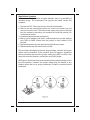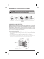
1
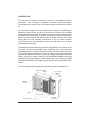
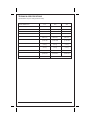
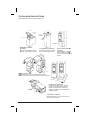
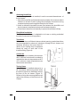
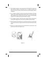
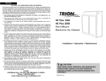
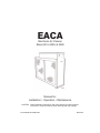
EACA
Electronic Air Cleaner
Sizes 0014, 0020, & 2020
Manual for:
Installation • Operation • Maintenance
CAUTION: Read installation instructions and rules carefully for safe operation.
Exercise the usual precautions when working with high voltage.
Form # EACA-1SI / II EACA-14-1
Date 07/02
Table of Contents
Page
Safety Considerations & Introduction
1
Unit specifications
2
Facts you should know about your new Electronic Air Cleaner
1)
Regular dusting & "white dust"
4
2)
Ozone
4
3)
Air flow sensor operation
5
4)
High altitude applications
6
Replacing the ionizing wires
7
Common Q & A
8-9
Maintenance of your Electronic Air Cleaner
10
1)
Removing the cells and prefilter
10
2)
Washing the cells and prefilter(s)
11
3)
Replacing the cells and prefilter(s)
11
Common troubleshooting techniques
12
Installation instructions ( for use by authorized HVAC
contractors)
15-29
Technical troubleshooting flowchart
29-30
Replacement part list
31-32
List of figures
Page
Figure 1
Air flow sensor diagram
5
Figure 2
Reducing ozone in high altitude applications
6
Figure 3
Cleaning the ionizing-collector cells
10
Table 1
Symptoms of excessive arcing or zapping
12
Unit dimensions
13
Technical specifications
15
Typical HVAC system configurations
16
Figure 4
Sheet metal transitions
18
Figure 5
Turning vanes from improving air flow
18
Figure 6
Proper installation of cell spacer
19
Figure 7
Proper mounting diagram
21
Figure 8
Wiring the unit to the input power source
22
Figure 9
Electrical schematic diagram
26
Figure 10
Testing the power supply output
28
Troubleshooting flowchart
29-30
Unit p a r t s diagram
31-32
NOTE: Read the entire instruction manual before starting the installation.
Safety Considerations
Improper installation, adjustment, alteration, service, maintenance, or use
can cause explosion, fire, electrical shock, or other conditions which may
cause personal injury or property damage. Consult a qualified installer,
service agency, or your distributor or branch for information or assistance.
The qualified installer or agency must use factory authorized kits or
accessories when modifying this product. Refer to the individual instructions
packaged with the kits or accessories when installing.
Follow all safety codes. Wear safety glasses and work gloves. Read these
instructions thoroughly and follow all warning or cautions attached to the unit.
consult local building codes and National Electric Code (NEC) for special
requirements.
Recognize safety information. This is the safety-alert symbol
. When you
see this symbol on unit or in instructions and manuals, be alert to potential for
personal injury.
Understand the signal words DANGER, WARNING, and CAUTION. These
words are used with the safety alert symbol. DANGER identifies the most
serious hazards which will result in severe personal injury or death.
WARNING signifies a hazard which could result in personal injury or death.
CAUTION is used to identify unsafe practices which would result in minor
personal injury or product and property damage. NOTE is used to highlight
suggestions that will result in enhanced installation, reliability, or operation.
This manual provides information for location, installation, operation and
service. Before installation and use of the air cleaner, carefully read these
instructions to insure maximum benefits from the unit and to avoid needless
service costs that can result from improper installation.
1
INTRODUCTION
This electronic air cleaner is technically known as a two-stage electrostatic
precipitator. The air cleaner is designed to remove airborne particulates,
including dust, dirt, smoke, pollen, virus, spores, bacteria and mold, from indoor
air.
Air movement through the unit is provided by the heating, air conditioning or
ventilating system blower. As dirty air enters the air cleaner, the air passes
through a metal mesh prefilter. The prefilter prevents lint, pet hair and other large
particulates from entering the air cleaner. It its important that these filters be in
place to prevent excessive dirt loading of the air cleaner collector cells. These
filters extend the time between maintenance of the air cleaner collector
cells.This allows the ionizing-collector cells to provide clean air for a longer
period between washings.
The prefiltered air then passes through a two-stage Electronic Air Cleaner. In the
first stage, all airborne particulate, even submicron size, are electronically
charged (positive) as they pass through the ionizer. The ionizer field is set up by
a corona discharge emanating from the fine, tightly strung wires suspended
between two adjacent flat plates. In the second stage, the charged particulate
passes through an intense electrical field established between alternately
charged and grounded parallel collector plates. Here, the positively charged
particulate is attracted to the negatively ground plates and removed from the air
stream.
For a unit diagram and a complete listing of all parts, please see page 31-32.
2
UNIT SPECIFICATIONS
This air cleaner is easy to install, operate and maintain. Its basic components
are the:
Cabinet
Mounts to existing ductwork; houses the ionizing-collecting cells and
prefilters.
Ionizing-Collector Cells
Collect the dust, dirt and other particulates in the air. They contain the
ionizing and collecting sections as described on page 2. The cells must be
installed with ionizing wires on the air intake side. A spring contact is located
on the top of each cell and must be in position to make contact with the
contact board assemblies on the bottom of the power tray assembly.
Prefilters
Trap large particulates before it enters the ionizing-collector cells.
Power Tray Assembly
Contains the indicating light, solid state power supply, contact boards and
electrical controls including ON/OFF switch and safety interlock switch. A
power cord at the rear of the tray allows the unit to be connected to a
standard 120V outlet. A wiring compartment is provided at the rear of the tray
allowing the option to permanently wire the unit directly to a furnace control.
Air Flow Sensor (AFS)
Installed on certain models, this part controls the operation of the unit by
sensing the movement of air within the duct. This helps to reduce power
usage and prevents the possible buildup of ozone within the duct.
How to Identify Which Air Cleaner Model you own
The model number and serial number for your Electronic Air Cleaner can be
found on the data label located on the inside of the access door. This serial
number will be a ten (10) digit number.
3
FACTS YOU SHOULD KNOW ABOUT YOUR NEW
ELECTRONIC AIR CLEANER
Dusting and "White Dust"
Your new Electronic Air Cleaner will efficiently clean and filter your household
air. Unfortunately, it will not eliminate the need for regular dusting of your
furniture and belongings. Due to the design of all duct-mounted air cleaners,
they can only clean the air that reaches the air cleaner. Therefore, if the
particulates are not being carried to the air cleaner in the air stream, the air
cleaner cannot remove them from your home.
Occasionally a "white dust" may be noticed in bedrooms or newly furnished
rooms. This is mainly composed of lint which, because it is heavier than other
particulates, settles before it reaches your unit.. This "white dust" is not mixed
with airborne dirt particles, therefore, it is clean and has no staining or soiling
properties. However, running the furnace blower continuously, day and night,
will help reduce this from occurring.
Ozone
Under normal operating conditions all Electronic Air Cleaners produce
minute quantities of ozone as an incidental by-product. In fact, all electronic
products, such as televisions, cordless phones and refrigerators, produce
some amount of ozone. The average homeowner can detect the smell of
ozone concentrations as low as 25 to 100 ppb (parts per billion). The design of
this unit has been tested and ozone production is approximately half of the
published permissible limits established by the Environmental Protection
Agency. These limits recommend that the concentration of indoor ozone not
exceed 50 ppb. Ozone is not harmful in these concentrations. In fact, the
ozone level in major cities can sometimes reach as high as 100 ppb on a
summer day. The addition of optional charcoal after-filters can help reduce
this.
Normally, a new unit will produce more ozone than one that has been in
operation for several weeks. This is due to sharp corners or manufacturing
burrs on the ionizing-collecting cell(s) and is normal. As the Electronic Air
Cleaner arcs and zaps, the voltage is vaporizing these areas and tends to
round them off. This is part of the breaking-in period of ownership and the
issue is self-correcting. Also, high-altitude locations can be more susceptible
to noticing the presence of ozone.
An ionizing-collecting cell that has been damaged or bent (the designed
spacing between electrically charged and ground components has been
decreased) may also produce an abnormal amount of ozone.
4
How the Air Flow Sensor Works (available on specific models)
The electronic AFS was designed to provide an efficient and reliable method
of controlling the operation of the air cleaner when the dealer is unable to
wire the unit directly into the furnace blower. The electronic AFS utilizes a
thermistor that heats up to approximately 130°F. The AFS then stabilizes at
this temperature and when the furnace blower turns on and air flows through
the ductwork, the same vacuum effect pulls cooler air over the hot surface.
This air movement cools down the thermistor and this cooling down effect
allows the electronic AFS to understand that the furnace blower is moving air
and the Electronic Air Cleaner must turn on to provide air cleaning.
If the air cleaner is installed in a location that is dusty and dirty, the sensor on
the AFS can become coated with dirt and lint. This coating can insulate the
AFS and keep it from operating properly. To clean the thermistor, take a
cotton swab dipped in rubbing alcohol and carefully insert it into the hole
located on the right hand side of the power pack assembly (when facing the
unit). The hole is 3/16 " in diameter and is located on the front of the power
tray assembly. Carefully twirl the cotton swab between your fingers, making
sure the tip is lightly in contact with the grey disc, cleaning this coating from
the thermistor.
AFS TROUBLESHOOTING
It is recommended that the following procedure only be performed
by an authorized HVAC contractor. Failure to do so may expose an
individual to personal injury
1. Make sure the furnace blower is not operating, the rocker switch
is OFF and the circuit breaker is turned OFF or cord is
disconnected.
2. Remove the access door.
3. Remove power tray assembly.
4. Locate the AFS. It is a circuit board with a small grey disc
connected to the circuit board by two(2) silver wires (similar to
Figure 1). Carefully bend the thermistor so that it is located in the
center of the opening and approximately 1/8" from the inside edge
of the power pack assembly.
5. Reinstall the power tray assembly and access door.
5
High Altitude Operation
Because the air is less dense at higher altitudes, there is a possibility of
nuisance arcing. The homeowner can quickly and easily correct this
condition.
1. Turn the unit OFF. Disconnect cord or turn off circuit breaker.
2. Remove the two screws that secure the cover to the power tray and
remove it from the unit. (The entire power supply tray may be removed
from the cabinet by removing two screws from inside the cabinet.) Do
not lose these screws.
3. Locate the jumper terminal (see figure 2).
4. With a pair of needle nose pliers, carefully adjust the jumper settings
from HIGH to MED. Ensure that the jumper is firmly seated in the
terminal.
5. Replace the power tray cover and secure it with the two screws.
6. Replace the access door and turn the unit ON.
This procedure will slightly reduce the output voltage, minimize arcing and
reduce ozone production. If the condition does not improve, repeat the
above procedure and move the jumper setting from MED to LOW. If this
does not correct the situation, contact your local HVAC dealer.
All Electronic Air Cleaners are produced at the factory with the jumpers set in
the HIGH position. However, the output voltage may be lowered in any
situation where the unit is arcing excessively or there is excessive ozone
production.
6
REPLACING THE IONIZING WIRES
Ionizing wire breakage is minimal because of the constant tension design
and fixed location of the ionizing wire supports. When an ionizing wire
breaks, the efficiency of the Electronic Air Cleaner will decrease slightly.
However, the unit will continue to operate with broken ionizing wires as long
as the broken wires have not caused a short circuit of the unit. Remove all
loose and broken wires as soon as they are identified.
Although the replacement of the ionizing wires can be attempted by a
homeowner, it is recommended that a qualified HVAC contractor be
contacted for replacement parts and/or servicing. Wires are supplied in a
coiled spring configuration, with a clinch nut on each end of the wire.
Replacement requires a pair of needle nose pliers. Exercise caution in
removing any broken wires in the collector cell. This will prevent accidental
shorting of the cell and reduce the need for further maintenance.
Use the following procedure when replacing an ionizing wire.
1. Ensure that all power to the Electronic Air Cleaner is OFF, remove the
access door and remove the ionizing-collector cells from the unit.
2. Carefully remove all remains of the broken wire.
3. Grip the new wire at each end of the wire with your thumb and index
finger. While stretching the wire to approximately 6" allow one end of
the wire to uncoil between your thumb and index finger.
4. Place one end of the wire in the slot of the stainless steel support on
the collector cell from the front of the cell. This support is partially
covered by the cell brace in front of the support.
5. Grip the other end of the ionizing wire with needle nose pliers and
insert the terminated end of the wire into the slot on the support bar of
the opposite end of the collector cell.
6. The wire should be tight enough to be self supporting and remain
suspended between the two support slots in the support bar.
7
Common Questions and Answers
Q. Why isn't my air cleaner cleaning my air?
A. The air cleaner is most likely working just like it was designed.
However, many factors can affect the performance of the unit. Are cold air
registers located in the ceiling? If so, it will be difficult for the air flow to
carry heavier particulates to the air cleaner. If the dirt doesn't get to the air
cleaner, it can't be removed from the air. Are both the Red and Green lights
illuminated? If not, then the unit may be in need of servicing. Contact your
local HVAC dealer for assistance.
Q. It still isn't cleaning my air the way I want it to. What can I do?
A. We recommend that you run the blower continuously so that the air
movement will carry the dirt to the air cleaner. Unfortunately, there will
always be some dirt that is left behind on the appliances, furniture, etc.
Regular dusting is recommended to stir up these pockets of dust so that
they can enter the airstream and be removed by the Electronic Air Cleaner.
Q. When I turn on my Electronic Air Cleaner, the lights come on for a couple
of seconds and then turn off. The air cleaner isn't working!
A. The air cleaner is fine as long as both the Red and Green lights are
coming on. Try turning the HVAC blower OFF and then turning the
Electronic Air Cleaner on. This should solve the problem.
Q. What is the zapping noise I'm hearing from my unit? Should I be
concerned?
A. The zapping or popping noise that you are hearing is the sound of larger
particles being "vaporized" by the ionizing-collector cell. This is normal
and is no cause for alarm. As your HVAC system blower moves the air
through the ductwork and allows the Electronic Air Cleaner to clean the
air, the noise will diminish. However, there will always be instances when
larger particles enter the ionizing-collector cell.
Q. Should I hear this zapping noise all the time?
A. All Electronic Air Cleaners will occasionally zap or pop as larger particles
pass through the ionizing-collector cells. However, if the sound is
constant or is repetitive in nature, then a large particle may have become
lodged in the ionizing-collector cells and they may require cleaning. If
cleaning the ionizing-collector cells does not stop the noise and there
are no large particles trapped in the ionizing-collector cells, then the
cause could be a broken/loose ionizing wire, bent collector plate or
other mechanical reason. Please contact your local HVAC dealer for
assistance.
8
Q. What if I no longer hear any popping or zapping noises coming from
my unit? Is it still cleaning the air?
A. If the zapping noises stop and the air cleaner is not in need of
servicing, then one of two situations has occurred. First, the Electronic
Air Cleaner has successfully removed all larger particles from the air
and is cleaning microscopic particles which do not cause the zapping
noise. Second, the blower and/or HVAC system is not running and air
is not flowing through the ductwork. The Electronic Air Cleaner cannot
remove particles if the air stream is not moving.
Q. I lost power to my home during a storm. Should I worry about the
Electronic Air Cleaner?
A. The most common problem associated with power outages is the unit
will not turn on properly after power is restored. If the Red and Green
light come on for a couple of seconds and then go off, the unit is
OK. Just turn the HVAC blower off, turn the unit ON and then turn the
blower back on. If the Red and/or Green light does NOT come on
after a storm, the power supply in the Electronic Air Cleaner may be
short circuited. Contact a local HVAC contractor for further
information.
Q. My installer told me to keep my HVAC system blower running all the
time, but I don't want to increase my power bill. What should I do?
A. It is recommended that you keep your HVAC system blower running
all the time to achieve the maximum air cleaning efficiency. This will
allow the Electronic Air Cleaner to do what it is designed to do, which
is clean the air. Remember that if the air does not reach the air cleaner,
it cannot be cleaned. On average, your Electronic Air Cleaner will use
the same amount of electricity as a 55W light bulb. The energy usage
of the HVAC system blower will depend on the age of your system ,
energy costs in your regional location and other variables. The best
solution is to try running the HVAC system blower in continuous mode
for a month or two to estimate your annual energy costs and base
your final decision on what you feel most comfortable with.
9
MAINTENANCE OF YOUR ELECTRONIC AIR CLEANER
WARNING :Handle ionizing-collector cells with care as plates
can be sharp and cause injury if not handled properly.
WASHING CELLS AND PREFILTERS
Regular washing is necessary to ensure proper performance. A thorough
washing once every two months will be adequate for most installations.
More frequent washing (once a month) may be necessary on some
installations (new homes for example) where there is new carpeting, plaster
dust, or excessive cigarette smoke (Figure 3).
To remove cells and prefilter
1. Push air cleaner switch to the OFF position. Wait 15 seconds. Open door
access panel.
2. Carefully remove cells and prefilter(s) and set aside in a safe place.
3. Do not drop the ionizing-collector cell. This could cause damage to the
cell plates or ionizing wires and cause excessive arcing and noise.
10
To wash cells and prefilter(s)
We suggest that you follow the instructions below to properly and
thoroughly clean your collector cells.
1. Place enough hot water in a utility tub to cover the first cell. Dissolve 2
to 4 oz. of granulated automatic dishwasher detergent (not laundry
detergent) in the water.
2. Allow the cell to soak for 30 minutes. Agitate it up and down in the
solution until it appears clean and remove.
3. Repeat with second cell.
4. Agitate the prefilters up and down in the solution until they appear
clean.
5. With a hose, rinse the cells and prefilters. The hose should be held
about 10" from the cell plates and at a slight angle for better cleaning
results. Be careful not to spray the ionizing wires directly with the
hose. The water pressure can cause the wire to snap and break. The
cell frame should be thoroughly rinsed along the edges to dislodge
any trapped lint or dirt. Carefully wipe a damp cloth or sandpaper (not
emery cloth) along the ionizing wires.
6. Stand cells and prefilters up to drain. Let dry two hours. You may
experience a slight discoloration of the aluminum collector cells after
washing. This is a normal chemical reaction and will not harm your
unit or affect its performance.
To replace cells in air cleaner
1. Replace prefilter and cells in cabinet. Check that arrow on cells points
in same direction as air flows through the duct. (If you have to force it
past the positioning screw on bottom, it is probably in the wrong
position.)
2. Replace access door (engage tabs on lower edge of door into slots in
cabinet). Carefully close door.
3. Turn air cleaner switch to ON.
11
COMMON TROUBLESHOOTING TECHNIQUES
SYMPTOM
Rapid arcing or zapping
Excessive ozone smell
Excessive ozone smell
Hissing or sizzling noise
Green LED light is not ON
Red LED light is not ON
POSSIBLE CAUSES
CORRECTIVE ACTION
Broken or loose ionizing wire(s)
Remove broken or loose wire and
replace with new wire
Dirty ionizing-collector cell
Clean as outlined on page 10-11
Damaged or bent collector plates
Straighten plates with needlenose
pliers or replace entire ionizingcollector cell.
Dirty insulator caps on ionizingcollector cell
Clean with warm soapy water and
rinse well
Air cleaner is wired directly to a
120V power source
Qualified HVAC contractor must
install AFS or rewire air cleaner
To the HVAC system blower
Loose high voltage connections
Repair or replace the component
Radio or television interference
Uncommon occurance -check for good common ground
for air cleaner
Poor electrical contact
Ensure that there is a good
connection between the top of
the ionizing-collector cell and the
bottom of the contact board
assembly
Contact HVAC contractor
No power available
Reset circuit breaker
Replace fuse
Loose wiring at ON/OFF switch
Check for secure connection
Defective ON/OFF switch
Replace ON/OFF switch
ON/OFF switch not in ON position
Turn the unit ON
Loose wiring within power pack
assembly
Check for secure connections
Contact HVAC contractor
Broken or shorted electrical
component
Contact HVAC contractor
Excessive dirt build up on ionizing
wires
Clean wires with alcohol and
allow to dry thoroughly before
turning the unit ON
Contact board assemblies are
corroded or carbonized
Replace contact board assembly
Broken ionizing wire
Remove broken wire and replace
with new wire
Dirty ionizing-collector cell
Clean as outlined on page 10-11
Foreign object located between
collector plates
Remove object from ionizingcollector cell
Damaged or bent collector plates
Straighten with a pair of needlenose pliers or replace cell
Insulators are corroded or
carbonized
Replace insulators or ionizingcollector cell
Table 1
12
UNIT DIMENSIONS - All dimensions in inches (mm)
EACA
Models
A
B
Inches MM
C
D
E
F
G
Inches MM
Inches MM
Inches MM
Inches
MM
Inches
MM
0020
24-1/4
616
17-7/8
453
20-15/16 531
22-1/2 572
24-7/8
632
7-1/8
181 21-7/16 545
0014
20-1/4
514
13-7/8
352
16-15/16 429
22-1/2 572
24-7/8
632
7 1/8
181
21-7/16 545
2020
24-1/4
616
17-7/8
453
20-15/16 531
21-3/8
543
7-1/8
181
18-5/8
19
483
Dimensions are the same for both models with and without Air Flow Sensors installed
13
Inches MM
473
WARNING
Only a trained, experienced serviceman
should install this electronic air cleaner.
A thorough checkout of the unit installation
should be completed before unit
operation. Electrical shock can cause
serious injury or death.
14
TECHNICAL SPECIFICATIONS
(Specifications subject to change without notice.)
MODEL NUMBER-EACA
DIMENSIONS (IN)
UNIT COLOR
AIR FLOW SENSOR INSTALLED
ELECTRICAL INPUT
0014
0020
2020
20 1/4 x 7 1/8 x 24 7/8
24 1/4 x 7 1/8 x 24 7/8
24 1/4 x 7 1/8 x 21 3/8
American Sterling
American Sterling
NO
YES
120V, 60 Hz, 1 PH
240V, 60Hz, 1PH
American Sterling
NO
120V, 60 Hz, 1 PH
MAXIMUM RATED AIR FLOW
1400 CFM
(2380 m³/hr.)
2000 CFM
(3400 m³/hr.)
1400 CFM
(2380 m³hr.)
MAXIMUM PRESSURE DROP
.11 inch w.g.
@1400 CFM
.14 inch w.g.
@ 2000 CFM
.11 inch w.g.
@ 1400 CFM
CELL WEIGHT (2 CELLS IN EACH UNIT)
10 lbs. each
(4.45 kg)
12 lbs. Each
(5.45 kg)
9 lbs. Each
(4.10 kg)
UNIT WEIGHT
32 lbs
(14.6 kg)
36lbs
(16.4 kg)
36 lbs.
(16.4 kg)
MAXIMUM POWER CONSUMPTION
40 watts
48 watts
40 watts
2.5mADC
@ 6200 kVDC
3.2 mADC
@ 6200 kVDC
2.5 mADC
@ 6200 kVDC
UL/CUL
UL/CUL
UL/CUL
ELECTRICAL OUTPUT
CLASSIFICATION
15
TYPICAL MOUNTING POSITIONS
Shaded illustrations are for positioning use only
AIR FLOW
AIR FLOW
SHEET METAL
TRANSITIONS
AIR CLEANER
AIR CLEANER
AIR FLOW
SHEET METAL
TRANSITIONS
AIR CLEANER
BASEMENT FURNACE
(LOWBOY)
Mounted horizontally in return
plenum - just above the furnace
COUNTERFLOW FURNACE
Mounted horizontally in return
duct - just above the furnace
SPACE SAVER FURNACE
(HIGHBOY)
Side installation. Cleaner is
mounted vertically, where
return air enters side inlet of
furnace.
AIR FLOW
AIR FLOW
BEFO
AFTER
RE
AIR CLEANER
OFFSET INSTALLATION
If there is less than 7-in. for mounting the air cleaner
between the duct and the furnace, move the return air drop.
AIR CLEANER
AIR FLOW
SPACE SAVER (HIGHBOY)
Installation beneath furnace. Cleaner
mounts horizontally, where return air
enters from below. Raise furnace by
installing a suitable wood structure and
install air cleaner.
AIR CLEANER
BLOWER DOOR
HORIZONTAL FURNACE
Mounted vertically in return duct as close to
the furnace as possible
16
PLANNING THE INSTALLATION
Application
The air cleaners are used in forced air heating cooling and ventilating systems. The
air cleaner should be installed in the system so that all the system air is circulated
through the air cleaner. The air cleaner will only remove the airborne contaminants
delivered to it. Maximum performance is obtained when the system blower is set for
continuous operation.
Installation Requirements
The best location for the air cleaner is in the return air duct next to the blower
compartment. In this location, the blower motor and cooling coils will be kept clean.
DO NOT INSTALL THE AIR CLEANER
IN THE DISCHARGE AIR DUCT.
Before installing the air cleaner, consider the application and type of HVAC system
present. Refer to the section entitled Typical Mounting Positions,
for the most common types. If a transition between the ductwork and air cleaner is
required, refer to section entitled Transitions. The unit must be readily accessible
for periodic inspection and cleaning of the prefilters and electronic cells to maintain
maximum efficiency and trouble-free operation.
Air Conditioning
The air cleaner should be installed upstream of the cooling coil. This will keep the
coil clean and reduce air conditioning coil maintenance. Improved cooling
efficiency is the result and directly affects energy costs. A clean coil, will reduce
utility costs. If the air cleaner is downstream of the cooling coil, condensation will
form on the cooled collector plates when the air conditioner cycles. This will allow
water droplets to form on the collector plates and cause nuisance arcing. Arcing will
reduce air cleaner efficiency and reduce the life of the high voltage power supply.
Humidifiers
An evaporative humidifier can be mounted upstream of the air cleaner. It is best to
install an atomizing humidifier downstream of the air cleaner because hard water
salt deposits and water droplets may damage the air cleaner. If an atomizing
humidifier must be mounted upstream of the air cleaner:
1. Mount it as far upstream as possible. (Recommended at least 6 feet.)
2. Install a standard disposable furnace filter between the humidifier and
the air cleaner to trap water droplets and hard water salts.
3. Clean the air cleaner more frequently to prevent a hard water salt
buildup.
Outdoor Air
When outdoor air is added to the return air duct, sufficient heat should be added to
maintain the return air temperature at 40°F (4°C) minimum. Lower temperatures can
cause ionizer wire failure.
17
Atomizing Humidifiers
If an atomizing humidifier is installed, it must be mounted downstream of
the air cleaner.
1. Mount the humidifier as far downstream as possible. It is recommended a
distance of at least 10 feet to reduce the possibility of excessive arcing
as water droplets pass through the Electronic Air Cleaner.
2. Install a standard disposable furnace filter between the humidifier and
the air cleaner to trap water droplets and hard water deposits.
3. Clean the air cleaner more frequently to prevent a hard water buildup.
Sheet Metal Installation
The Electronic Air Cleaner is adaptable to all new or existing residential
forced air furnace and cooling systems.
Transitions
If the air duct does not fit the air cleaner cabinet opening, gradual transitions
are recommended to reduce air turbulence through the air cleaner and
maximize efficiency. Not more than 20°
(about 4" per running foot) of expansion
should be used on each side of the
transition fitting (Figure 4).
Turning Vanes
If the air cleaner is installed adjacent to a
90° duct elbow, add turning vanes inside
the duct to improve air distribution across
the face of the air cleaner (Figure 5).
Failure to follow the recommendation can
reduce the efficiency of the Electronic Air
Cleaner.
18
AIR FLOW
FURNACE
OPENING
Outdoor Air
When outdoor air is added to the return air
duct, sufficient heat should be added to
maintain the return air temperature at 40°F
(4°C) minimum. Lower temperatures can
cause ionizer wire failure.
AIR CLEANER
OPENING
AIR FLOW
FURNACE
AIR CLEANER
TRANSITION SECTION
SELECT LOCATION FOR AIR CLEANER
Remember to select a location that is readily accessible for periodic
inspection and cleaning of this air cleaner. Allow a minimum of 24"
clearance in front and 12" clearance above the air cleaner for component
removal and service space. For complete dimensions required refer to the
section entitled UNIT DIMENSIONS.
DIRECTION OF AIR FLOW THROUGH THE AIR CLEANER
This air cleaner is set up for left to right air flow when you are facing the
access door.
For right to left air flow, follow these directions:
1. Remove the prefilter(s) and cells from the
cabinet. A plastic positioning spacer is
located inside the bottom of the cabinet.
This spacer is secured to the cabinet using
a #6-32 round head Phillips drive thread
cutting screw to assure installation of the
cells in the proper position with respect
to air flow (Figure 6).
2. Remove the screw and reposition the
spacer in the alternate hole at the bottom of
the cabinet.
3. Replace the screw to insure the plastic spacer is not accidentally
knocked out of place during normal maintenance. It must be installed in
the hole provided closest to the air leaving side of the cabinet. Seal the
unused hole with duct tape.
4. Remove the cell handle and reattach to the opposite end of the cell. Turn
cells around, replace in cabinet and replace prefilters on the air
entering side. The directional arrows on the cell end plates must point in
the direction of air flow.
19
INSTALLATION
CAUTION: Only a trained, experienced serviceman should
install this electronic air cleaner. The power supply should be
removed before installation. To remove the power supply, remove
the two (2) screws (See Figure 7) in the top front of the cabinet.
Remember to keep this hardware for reinstallation of the power
supply when the air cleaner installation is complete. A thorough
checkout of the unit installation should be completed before unit
operation.
PHYSICAL INSTALLATION OF THE AIR CLEANER
This Electronic Air Cleaner can be installed in any position, except with the
access door facing down. The section entitled TYPICAL MOUNTING
POSITIONS show examples of proper air cleaner mounting with a variety of
furnace installations.
Prior to installing this product...
1. Read rules and instructions carefully for safe operation. Failure to follow
them could damage the product or cause a hazardous condition.
2. Check the ratings given on the product to make sure it is suitable for your
application.
3. Select a location for the air cleaner.
4. Remove the old furnace filter and discard.
5. The air cleaner cannot remove existing dirt from the blower and ducts.
Clean the area thoroughly before you begin.
6. Remove unit access panel, and slide the prefilters and ionizing-collecting
cells out of the cabinet. Place them safely aside with the warranty and
registration card.
NOTE: The following is a typical installation of the air cleaner on a
highboy furnace. You may have to alter the installation to fit your
particular application.
20
7. Locate the cabinet in the cold air return duct so that all of the return air
flows through the unit (Figure 6). If the furnace and air cleaner openings
are different, use a transition (Figure 4).
8. Mounting holes are provided for
ductwork attachment (Figure 7). The
.140" holes are sized for #8 sheet
metal screws, or 1/8" rivets. If the
adjoining ductwork is flanged, install
the screws so that the screw heads
are inside the cabinet. This will prevent
damage to the prefilters and
optional charcoal after-filter during
removal and installation after
cleaning.
9. After the unit has been secured, seal
seams air tight with duct tape or
caulking.
ATTENTION: On Electronic Air Cleaners that have the air flow sensor
installed at the factory, be especially careful not to cover the air flow
sensor orifice when sealing the air cleaner and ductwork. This hole is
located on the right hand side of the enclosure that holds the power
pack assembly (when facing the unit). The hole is 3/16" in diameter and
is located on the front of the power tray assembly. In applications with
minimum air flow, it is helpful to seal any openings on the power tray
assembly or cabinet. This will increase the velocity of air flowing over the
air flow sensor, enabling the air flow sensor to turn the Electronic Air
Cleaner on and off. The only opening required for actuation of the
air flow sensor is the 3/16" diameter hole previously described.
10. Refer to the section entitled DIRECTION OF AIR FLOW.
11. Install prefilters and ionizer-collector cells.
12. Reinstall power tray assembly into the cabinet.
13. Reinstall unit access panel.
21
ELECTRICAL INSTALLATION
All wiring must comply with applicable local and national codes.
CAUTION:
Be sure all incoming power is OFF before beginning any procedures.
CAUTION:
The following instructions are for use by qualified personnel only.
WARNING:
The following procedures will expose hazardous live parts. Disconnect power between checks and
proceed carefully. Electrical shock can cause injury or death.
The Electronic Air Cleaner (without the AFS installed at the factory) is designed to take advantage of the integrated
accessory control panel available on most furnaces. The 120V Electronic Air Cleaner tap on the furnace will provide
power to the air cleaner only when the circulating air blower is in operation.
Read the instructions in the furnace installation manual carefully before attempting installation or operation. Failure to
follow these instructions may result in improper installation and therefore void warranty.
An optional(on 120v model) electronic air flow sensor kit is available if the air cleaner is not equipped with an AFS. This
air flow sensor will sense the air movement within the duct and turn the Electronic Air Cleaner on and off accordingly.
CAUTION
This unit cannot be powered directly from blower motor
leads. Voltages can exceed 190vac for 120-v. motors or
possibly double with 240-v. fan coil motors.
Figure 8
WIRING PROCEDURE
This air cleaner is powered by providing power to pigtail
leads at field wiring compartment (see knock-out holes)
located at the rear of the power pack assembly (See Fig.
8).
1. Turn air cleaner OFF using ON/OFF switch located on
front panel.
2. Remove power pack cover plate by removing front
door and two screws holding assembly to the top of
the air cleaner.
3. Make wiring connections inside junction box area
(See Fig. 8). Remove knock-out and use conduit or
other approved methods to supply input power.
Connect ground wire to clip.
4. Replace the power supply cover plate and secure with
screws removed from step 2.
5. Replace the unit door to the front of the air cleaner.
6. Air cleaner will now operate when door is in place,
ON/OFF rocker switch is in the ON position and input
voltage is present in the junction box. The following
should be completed to supply input power to the air
cleaner.
FURNACE APPLICATION
It is recommended to use EAC 1 and EAC 2 terminals
when provided by the furnace circuit board. These
outputs will provide 120 vac whenever the blower motor
is energized.
Furnace circuit boards without EAC 1 and EAC 2
terminals MUST use alternate methods to supply to
supply power to the air cleaner. Options include Sail
Switch , Isolation relay or Optional AFS (Air Flow Sensor).
Air cleaner should only operate when blower motor is
running.
FAN COIL APPLICATION of 0014 or 0020 Models (120-v.)
If EAC 1 and EAC 2 terminals are provided by fan coil
circuit board, refer to fan coil data to determine voltage
output. Most fan coils do not provide 120-v. at these
terminals. Alternate methods may be needed to convert
fan coil supply voltage to 120-v. for the cleaner. A 240-v. to
120-v step down transformer (60 v.) will be needed in most
applications. Sail Switch, Isolation relay or Optional AFS
(Air Flow Sensor) may also be needed.
FAN COIL APPLICATION of 2020 Model (240-v.)
The Model 2020 is a 240-v. power supply model designed
to match you fan coil. To install this model with a 240-v. fan
coil:
CAUTION
This unit cannot be powered directly from blower motor
leads. Back EMF (electro magnetic field) voltages can
reach 400 vac for 240-v. fan coil motors.
1. Turn air cleaner OFF using ON/OFF rocker switch
located on front panel.
2. Remove power pack cover plate by removing front
door and two screws holding assembly to the top of the
air cleaner.
3. Make wiring connections inside junction box area (See
Fig. 8). Remove knock-out and use conduit or other
approved methods to supply input power. Connect
ground wire to clip.
4. Replace the power supply cover plate and secure with
screws removed from step 2.
5. Replace the unit door to the front of the air cleaner.
6. Air cleaner will now operate when door in place,
ON/OFF rocker switch is in the ON position and input
voltage is present in the junction box.
22
SYSTEM CHECKOUT
WARNING: The following procedures should be conducted by a
qualified HVAC contractor or repair person ONLY. These procedures
will expose hazardous electrically energized charged components.
Disconnect power between checks and proceed carefully.
1. The HVAC system blower should be turned OFF.
2. Switch the ON/OFF rocker switch to the ON position. The bright red
segment of the rocker switch should be visible.
3. Inspect both the Green INPUT POWER light and the Red CELL
ENERGIZED light:
• If the unit has an AFS installed, the lights should go out in
approximately 20 to 60 seconds. This is the normal time for the
electronic air flow sensor to complete its stabilization period. Both
lights will come back on when the HVAC system blower begins to
operate. See the section entitled HOW THE AIR FLOW SENSOR
WORKS for more information
• If the unit is wired directly to the HVAC system blower, the lights will not
come on until the blower begins to operate. In this case, the electronic
air cleaner will stay on as long as the ON/OFF switch is in the ON
position and the blower is operating.
• If the unit is wired directly to a dedicated 120V power source, the lights
will come on immediately and stay on for as long as the ON/OFF
switch is in the ON position, regardless of the HVAC system blower
operation. This type of installation is NOT recommended due to the
excessive production of ozone. See the section entitled FACTS YOU
SHOULD KNOW ABOUT YOUR ELECTRONIC AIR CLEANER OZONE for more information.
4. Wait approximately one (1) minute and turn the HVAC system blower
ON. Most thermostats have a setting that will allow you to run the fan
manually. If not, then set the thermostat so that either hot or cold air
begins to flow through the ductwork.
5. The Green INPUT POWER light and Red CELL ENERGIZED light should
come on, if the unit is wired directly to a dedicated 120V power source,
the lights will already be on and will not be affected by the HVAC system
blower operation (see Step 3).
6. Check to make sure that the Red CELL ENERGIZED light goes out when
the following conditions occur:
• Cell access panel is removed
• Rocker switch is switched to the OFF position
• HVAC system blower is not running.
23
TROUBLESHOOTING
•
•
•
•
•
CAUTION:
These procedures should only be attempted by a qualified HVAC
technician or electrician.
Risk of personal injury could occur by attempting to troubleshoot or
repair this unit by untrained persons.
Exercise the usual precautions when working with high voltage.
When the circuit has been de-energized, always discharge any
residual current in the secondary with an insulated handle
screwdriver.
Always ground power supply and ionizing-collecting cell when
bench testing.
Recommended Service Tools
•
•
•
•
•
Screwdriver, 8" common with insulated handle (plastic)
Screwdrivers Phillips #1 and #2 with plastic insulated handles
Needle nose pliers
Multimeter
High voltage probe
Indication of Electrical Trouble
The air cleaner is equipped with a Red CELL ENERGIZED light for indicating
proper unit operation. When the unit is in normal operation (with the HVAC
system fan running, access door in place and rocker switch in the ON
position) and the Red CELL ENERGIZED light is not lit, the problem is a
shorted secondary. Although failure of the indicating light itself should not
be overlooked, this condition is unusual and rather remote.
24
PRIMARY CIRCUIT WITH FURNACE BLOWER OPERATING
If there is supply line voltage at the connections and no input voltage to the
power supply, the outage can be located by checking operation of the
safety switch and the interconnecting wiring with a multimeter. Refer to
Circuit Diagram, (Figure 9) to check operation of the switches.
Following these steps to test for proper operation of the circuit board and
power supply assembly:
1. Ensure that the circuit breaker controlling the furnace blower is in the ON
position and the main fuse is not open.
2. The power supply board has a built-in internal fuse to protect the 24V
transformer. It can be checked visually by inspecting the fuse. If the fine
wire inside the fuse is broken, this indicates a problem in the 24V circuit of
the power supply board. Do NOT replace this fuse. The entire power
supply board must be replaced. The purpose of the fuse is not to protect
the power supply board, but to function as a troubleshooting feature of
the product and to protect the transformer from damage.
3. If the fuse is NOT blown, check the ON/OFF switches and safety interlock
switch for proper engagement and operation. This can be completed
using a volt ohm millimeter on a scale that will measure ohms as low as
1.0. If you are using the recommended meter previously mentioned in
this manual, set the meter to read 200 ohm and proceed with Steps 4
through 6.
4. Remove the fuse. Connect one lead to the test pin located directly beside
the wire that connects the ON/OFF switch to the power supply board.
Connect the other lead to the fuse connection closest to the front panel.
5. Turn the ON/OFF switch to the ON position and depress the safety
interlock switch. The meter should have the capability of reading levels
as low as 1.0 ohm.
6. If there is no reading on the meter, begin the process of elimination by
disconnecting the wire from the test point and connecting it to the
terminal with the blue wire located on the safety interlock switch. Depress
the safety interlock switch. If the reading on the meter is greater than 1.0
ohm, the safety interlock switch is defective and must be replaced. If the
reading on the meter is less than 1.0 ohm, the ON/OFF switch is defective
and must be replaced.
25
27
SECONDARY CIRCUIT
IONIZING-COLLECTING CELL
The cell is electrically energized through a contact terminal located at the top center
of the cell. The ionizing wires and alternating collector plates are electrically
charged while the interleaving plates are grounded.
If the space between the charged and grounded plates is bridged with conductive
or semi-conductive material, a short circuit develops. The bridging or short may be
caused by damaged plates, or foreign material lodged between/on the
components. Since the cell should be periodically removed from the unit to wash
away collected dirt, it is susceptible to physical damage. The cell also contains the
ionizing wires which, due to their function, have been designed with minimal
structural support and are susceptible to breakage. However, trouble related to a
shorted collector cell is readily shown by the Red CELL ENERGIZED light and can
be quickly isolated by a simple procedure.
To determine if a short exists in one or both of the collector cells, turn the Electronic
Air Cleaner OFF and remove both electronic cells from the cabinet. Shut the door
and repower the unit. If the Red CELL ENERGIZED light comes on, an electrical
short exists in one or both of the electronic cells. Replace the cells in the unit, one at
a time, to determine which cell is shorted.
Most troubles in the cell can be visually detected and corrected (page 12 - Table 1).
NOTE: The ionizer collector cells are not designed for field repair. Ionizing wires and
insulators can be field replaced. It is not recommended that you attempt to replace
other cell components (i.e. Collector plates, end plates, ionizer supports).
EACA-2020
EACA-0014 & 0020
240V
120V
Figure 9B
Figure 9A
26
CHECKING THE POWER SUPPLY
If the output light remains out with the collector cells removed from the
cabinet, the power supply is defective. Specific problems on the power tray
assembly can be isolated by using a multimeter and high voltage probe to
check the output voltages.
To check the secondary circuit, a high voltage meter is required. See the
section entitled RECOMMENDED SERVICE TOOLS. To check for proper
operation, it is imperative that the procedure be followed as outlined below:
1. Make sure the furnace blower is operating, the control switch is on and
input voltage is 120 volts, 60 Hz.
2. Remove front door assembly panel.
3. Remove power pack access cover.
4. Check the high voltage contact board assembly(s) for damage or carbon
tracking.
NOTE: The cell contacts should be visually checked for corrosion,
excessive dirt build up, and electrical arc tracking (Carbon path from
stainless steel spring to grounded metal). Clean or replace as required.
5. Make connections from the high voltage probe to the multimeter in
accordance with the operator's manual. The meter should be set for
reading DC voltage on the 20 volt full scale.
6. Attach the high voltage probe ground lead to the cabinet. While
depressing the safety switch lever, touch the ionizer wire support bar
with end of the high voltage probe (Figure 10). The meter reading should
be 6.2 kVDC ± .2 kVDC.
7. If no voltage is measured, remove the first cell and check the second cell.
The meter should read 6.2 kVDC ± .2 kVDC.
8. If proper voltage is measured, the first cell is shorted. Refer to Table 1, on
page 12.
27
9. If no voltage is present, remove the second cell. Install cell number one
and measure voltage as described above. If voltage is present, the
second cell, which is now out of the cabinet, is shorted. Refer to Table 1
on page 12.
10. If no voltage is present, remove both cells and measure the power
supply output. While depressing the safety switch, touch the end of the
high voltage probe to either the front or rear contact board assembly
(Figure 10). The meter should read 6.2 kVDC or higher.
11. If no voltage is present, check the power supply. Set the multimeter for
reading AC voltage at 200 volt full scale and attach meter test leads.
12. While depressing the safety lever, touch the two transformer output lead
junctions to the power supply board with the meter leads and read the
meter.
13. If there is no output voltage from 24 volt transformer, replace the 24 volt
transformer and power supply board.
28
TROUBLE SHOOTING THE DUCT MOUNT ELECTRONIC AIR CLEANER
No
Is the unit operating?
Is the furnace blower on?
Yes
No
Is input AC power available?
Yes
No
Is the safety interlock system OK?
Yes
Yes
No
Is ON/OFF switch working?
Is red light on?
No
Yes
Yes
Is cell dirty or defective?
No
No
Are contact boards OK?
Yes
Yes
No
Is the power supply wiring OK?
Yes
Yes
Is power supply defective?
No
Is transformer defective?
Is cell crackling and snapping?
NO
Is cell sizzling?
Yes
Yes
29
Yes
WARNING:
The following steps will expose hazardous live parts. Disconnect power between checks
and proceed carefully.
1. Replace any blown fuses and reset any tripped breakers.
2. Repair or replace any loose wires or bad connections.
3. Inspect AFS for proper location and operation.
1.
2.
3.
4.
Check that the access door is not open or ajar.
Repair or replace any loose wires or bad connections.
Replace defective momentary contact switch.
Inspect AFS for proper location and operation.
1.
2.
3.
4.
Ensure that ON/OFF switch is turned ON.
Repair or replace any loose wires or bad connections.
Replace defective ON/OFF switch.
Inspect AFS for proper location and operation.
1.
2.
3.
4.
Remove any objects between adjacent collector plates.
Replace corroded or carbonized insulators.
Replace any broken ionizing wires.
Wash dirty cells..
1. Replace contact board if contacts are corroded and carbonized.
2. Replace any defective wires.
3. With alcohol, clean dirt build-up on contacts and let dry thoroughly.
1. Repair or replace any loose wires or bad connections.
1. Replace defective high frequency power supply.
1. Replace power supply.
2. Replace transformer.
1. Wash dirty cell, including any powder build-up on ionizing wires.
2. Straighten any bent plates.
3. Replace any broken or loose ionizing wires.
1. Ensure good contact between cell and contact boards.
Replace defective contact boards..
30
Repeat these
steps until all
problems are
eliminated
EACA
31
EACA PARTS LIST
REF. DESCRIPTION NO..
1. Power Tray Assembly (W/ AFS) 120V
1A. Power Tray Assembly (W/ AFS) 240V
1B. Power Tray Assembly (W/O AFS)120V
2. High Frequency Power Supply
3. Electronic Air Flow Sensor (Optional)
4. ON/OFF Switch
5. Interlock Switch
6. Cabinet Assembly
7. Pre-Filter (2/ package)
8. Cell, Ionizing-Collecting
9. Ionizing Wire Assembly (Full Set / package)
10 Front Panel Assembly
11. Contact Board Assembly (2/ package)
12. Charcoal Filter (optional, not shown)(2/ package)
13. Stepdown Transformer 120V to 24V (0014 & 0020)
13A. Stepdown Transformer 240V to 24V(2020)
14. Insulator (6/ package)
15. Cell Key (not shown)
16. Power Tray Cover
OWNER RESPONSIBILITIES
The completion and return of the Warranty Registration Card is a condition precedent
to warranty coverage and performance. This warranty is not valid unless the warranty
card is completed and mailed to the factory within fifteen (15) days of equipment
installation.
32
Warranty
Two-Year Limited Warranty - This Product is warranted to be free from defects in material and
workmanship. If Defect appears within Two years from the date of original installation, whether or not actual
use begins on that date, product is warranted. If product installation criteria meets this standard, a new or
remanufactured part, at the manufacturer’s sole option, to replace any defective part will be provided
without charge for the part itself; PROVIDED the defective part is returned to the distributor through a
qualified servicing dealer.
Five-Year Limited Warranty on Power Supply - This Power Supply is warranted to be free from defects in
material and workmanship. If Defect appears within Five years from the date of original installation, whether
or not actual use begins on that date, product is warranted. If product installation criteria meets this
standard, a new or remanufactured part, at the manufacturer’s sole option, to replace any defective part will
be provided without charge for the part itself; PROVIDED the defective part is returned to the distributor
through a qualified servicing dealer.
Limited Labor Allowance - If service call on this unit must be made in the first 120 days from original date of
installation a $25.00 (USD) labor allowance will be given. If Power Supply must be replaces in the first five
years after original installation date a $50.00 (USD) labor allowance will be given.
THIS WARRANTY DOES NOT INCLUDE LABOR OR OTHER COSTS-OTHER THAN THAT SPECIFIED
ABOVE incurred for diagnosing, repairing, removing, installing, shipping, servicing or handling of either
defective parts or replacement parts. Such costs may be covered by a separate warranty provided by the
installer.
THIS WARRANTY APPLIES ONLY TO PRODUCTS IN THEIR ORIGINAL INSTALLATION LOCATION AND
BECOMES VOID UPON REINSTALLATION.
LIMITATIONS OF WARRANTIES – ALL IMPLIED WARRANTIES (INCLUDING IMPLIED WARRANTIES OF
FITNESS FOR A PARTICULAR PURPOSE AND MERCHANTABILITY) ARE HEREBY LIMITED IN DURATION
TO THE PERIOD FOR WHICH THE LIMITED WARRANTY IS GIVEN. SOME STATES DO NOT ALLOW
LIMITATIONS ON HOW LONG AN IMPLIED WARRANTY LASTS, SO THE ABOVE MAY NOT APPLY TO YOU.
THE EXPRESSED WARRANTIES MADE IN THIS WARRANTY ARE EXCLUSIVE AND MAY NOT BE
ALTERED, ENLARGED, OR CHANGED BY ANY DISTRIBUTOR, DEALER, OR OTHER PERSON
WHATSOEVER.
ALL WORK UNDER THE TERMS OF THIS WARRANTY SHALL BE PERFORMED DURING NORMAL
WORKING HOURS. ALL REPLACEMENT PARTS, WHETHER NEW OR REMANUFACTURED, ASSUME AS
THEIR WARRANTY PERIOD ONLY THE REMAINING TIME PERIOD OF THIS WARRANTY.
THE MANUFACTURER WILL NOT BE RESPONSIBLE FOR:
1. Normal maintenance as outlined in the installation and servicing instructions or owners manual including
filter cleaning and/or replacement and lubrication.
2. Damage or repairs required as a consequence of faulty installation, misapplication, abuse, improper
servicing, unauthorized alteration or improper operation.
3. Failure to start due to voltage conditions, blown fuses, open circuit breakers or other damages due to the
inadequacy or interruption of electrical service.
4. Damage as a result of floods, winds, fires, lightning, accidents, corrosive environments or other
conditions beyond the control of the Manufacturer.
5. Parts not supplied or designated by the Manufacturer, or damages resulting from their use.
6. Manufacturer products installed outside the continental U.S.A., Alaska, Hawaii, and Canada.
7. Electricity or fuel costs or increases in electricity or fuel costs from any reason whatsoever including
additional or unusual use of supplemental electric heat.
8. ANY SPECIAL INDIRECT OR CONSEQUENTIAL PROPERTY OR COMMERCIAL DAMAGE OF ANY
NATURE WHATSOEVER. Some states do not allow the exclusion of incidental or consequential
damages, so the above may not apply to you.
This warranty gives you specific legal rights, and you may also have other rights which may vary from state
to state.
Part Number 155587-005 • 7/02
Manufacturer reserves the right to discontinue, or change at any time, specifications or designs without notice and without incurring obligations.
Form No. EACA-1SI / IIEACA-14–1
Catalog No. 03EA-CA0
Printed in U.S.A.
7-02
Replaces: New