1
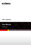
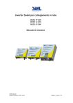
Preface
Thank you for choosing SAJ solar inverter. We are happy to provide you with first-class products
and quality service.
The manual includes installation, operation, maintenance, troubleshooting, and safety notice. As
long as you follow the instruction of this manual, you will get the professional guidance and our
wholehearted service.
Customer-orientation is our forever commitment. We hope this “User Manual” become your
good helper in solar power generation.
Please check the latest version at www.saj-solar.com
Guangzhou Sanjing Electric Co., Ltd.
User Manual
Contents
1. Information on this Manual...........................................................................................................................................1
1.1 Validity..............................................................................................................................................................................1
1.2 Target Group..................................................................................................................................................................,1
1.3 Symbols Used................................................................................................................................................................1
2. Safety........................................................................................................................................................................................2
2.1 Intended Use..................................................................................................................................................................2
2.2 Safety Precaution.........................................................................................................................................................2
2.3 Explanations of Symbols on Inverter...............................................................................................................4
3. Product Overview...............................................................................................................................................................5
3.1 Product Appearance...................................................................................................................................................5
3.2 Major Characteristics.................................................................................................................................................5
3.3 Technical Data...............................................................................................................................................................6
4. Installation Instructions..................................................................................................................................................8
4.1Unpacking....................................................................................................................................................................... 8
4.2 Mounting Instructions...............................................................................................................................................9
4.3 Mounting Procedure..............................................................................................................................................11
4.4 Optional Anti-Theft Protection.........................................................................................................................13
5. Electrical Connection.................................................................................................................................................... 14
5.1 Safety..............................................................................................................................................................................14
5.2 Overview of Connection Area...........................................................................................................................14
5.3 Connection Cables Requirements...................................................................................................................16
5.4 Miniature circuit breaker......................................................................................................................................17
5.5 Connecting the Electricity Grid (AC)............................................................................................................18
5.5.1Conditions for the AC Connection.................................................................................................................18
5.5.2 AC Connection procedure................................................................................................................................18
5.5.3 Connecting the Second Protective Conductor............................................................................................20
5.6 Connecting the PV Array (DC)...........................................................................................................................21
5.6.1 Conditions for DC Connection.......................................................................................................................21
5.6.2 Connection Procedures by H4:.......................................................................................................................22
5.7 Communication and Monitoring Setting......................................................................................................25
5.7.1 Communication through RS485....................................................................................................................25
5.7.2 Communication through Ethernet RJ45......................................................................................................27
5.7.3 Extended Wi-Fi Solution with Wi-Fi Bridge.............................................................................................27
5.7.4 Communication Cable Assembly Instructions...........................................................................................28
6. LCD Operation..................................................................................................................................................................31
6.1 LCD Display Overview..........................................................................................................................................31
6.2 Startup the Inverter...................................................................................................................................................32
6.3 LCD Main Screen......................................................................................................................................................33
6.4 LCD Menu Structure...............................................................................................................................................34
6.4.1 LCD Graph Submenu......................................................................................................................................35
6.4.2 LCD Setting Submenu.....................................................................................................................................36
6.5 Error Report Mechanism and Guidance........................................................................................................43
7. Recycling and Disposal................................................................................................................................................. 44
8. Troubleshooting................................................................................................................................................................ 45
9. Guaranty Service...............................................................................................................................................................50
10. Contact SAJ........................................................................................................................................................................50
User Manual
1.Information on this Manual
1.1 Validity
This User Manual describes instructions and detailed procedures for installing, operating,
maintaining, and troubleshooting of the following SAJ grid-tie inverters:
Suntrio-TL6K, Suntrio-TL8K, Suntrio-TL10K, Suntrio-TL12K
Suntrio-TL15K, Suntrio-TL17K, Suntrio-TL20K
Please keep this manual where it will be accessible at all times.
1.2 Target Group
This manual is for qualified electrically skilled person, who must strictly perform the tasks follow
this manual.
1.3 Symbols Used
DANGER
DANGER indicates a hazardous situation which, if not avoided, will result in death or
serious injury.
WARNING
WARNING indicates a hazardous situation which, if not avoided, can result in death or
serious injury or moderate injury
CAUTION
CAUTION indicates a hazardous condition which, if not avoided, can result in minor or
moderate injury.
NOTICE
NOTICE indicates a situation that can result in potential damage, if not avoided.
1
User Manual
2.Safety
2.1 Intended Use
The Suntrio-TL series inverters are PV inverter which converter the direct current of a PV array
into alternating current and feed this into the electricity grid.
The inverters are designed according to the safety rules. However, improper use, alteration or
modification may cause lethal hazards for the operator or third parties, or may result in damage
to the units and other property. SAJ is not responsible for the loss and invalidate these warranty
claims.
Figure 2.1 Grid-tie Solar System with Suntrio inverter
2.2 Safety Precaution
DANGER
● DANGER due to electrical shock and high voltage
● Do not touch the operating component of the inverter; it might result in burning or death.
● To prevent risk of electric shock during installation and maintenance, please make sure that all AC
and DC terminals are plugged out.
● Do not touch the surface of the inverter while the housing is wet, it might lead to electrical shock.
● Do not stay close to the inverters while there are severe weather conditions including storm, lighting,
etc.
● Before opening the housing, the SAJ inverter must be disconnected from the Grid and PV generator;
you must wait at least five minutes to let the energy storage capacitors fully discharged after
disconnecting from power source.
2
User Manual
WARNING
● The installation, service, recycling and disposal of the inverters must be performed by qualified
personnel only in compliance with national and local standards and regulations.
● Any unauthorized actions including modification of product functionality of any form
may cause lethal hazard to the operator, third parties, the units or their property. SAJ is not
responsible for the loss and deny these warranty claims.
● Suntrio inverters must only be operated with PV generator. Do not connect any other source of
energy to the inverters.
● Be sure that the PV generator and inverter are well grounded in order to protect properties and
persons.
CAUTION
● The PV inverter will become hot during operation. Please don’t touch the heat sink or
peripheral surface during or shortly after operation.
● Risk of damage due to improper modifications.
● Never modify or manipulate the inverter or other components of the system.
NOTICE
● The PV inverter is designed to feed AC power directly to the public utility power
grid; do not connect AC output of the inverter to any private AC equipment.
3
User Manual
3.Product Overview
3.1 Product Appearance
Figure 3.1 Suntrio inverters Overview
3.2 Major Characteristics
SAJ Suntrio inverter has following characteristics which make SAJ grid-tied solar inverter
“Higher Efficiency, High Reliability and Lower Cost”.
Leading technology
• Max. efficiency 98.1%
• MPPT accuracy up to 99.9% efficiency
User-friendly
• 5 inch LCD display with comprehensive information
• Embedded webserver monitoring
• Easy installation
Flexible
• Multi-country configuration
• RS485 / Ethernet / Wi-Fi communication
• Wide range of DC input voltage
• IP65 for indoor and outdoor
5
User Manual
3.3 Technical Data
Type
Input (DC)
Max. DC Power [W]
Max. DC Voltage [V]
MPPT Voltage Range [V]
Nominal DC Voltage
Start Voltage[V]
Min. DC Voltage[V]
Max. DC input Current PV1 / PV2 [A]
Number of MPPT
String(s) per MPPT
DC Switch
Output (AC)
Rated AC Power [W](@230V,50Hz)
Max. AC Apparent Power [VA]
Rated AC Current[A]
Max. AC Current [A]
Nominal AC voltage/ range
Grid frequency/ range
Total Harmonic Distortion (THDi)
Power factor, adjustable
Feed-in Phase / Connection Phase
Efficiency
Max. Efficiency
Euro Efficiency (at 600Vdc)
MPPT Accuracy
Protection
Internal Overvoltage Protection
DC Insulation Monitoring
DCI Monitoring
GFCI Monitoring
Grid Monitoring
AC Short Circuit Current Protection
Thermal Protection
Anti-island protection monitoring
Interface
DC Connection
LCD Display
Display Language
Datalogger & Communication
Device Data
Topology
Consumption at Night [W]
Consumption at Standby [W]
Operating Temperature Range
Cooling Method
Ambient Humidity
Altitude
Noise [dBA]
Ingress Protection
Dimensions [WxHxD] [mm]
Weight [kg]
Standard Warranty [Year]
Certificates
Suntrio-TL6K
6300
Suntrio-TL8K
8200
1000V
240~800
600
300
200
16 / 16
2
2
Optional
240~800
Suntrio-TL10K
10400
240~800
6000
8000
10000
6000
8000
10000
8.7
11.6
14.5
9.7
12.9
15.8
3/N/PE, 220/380V,230/400V,240/415V;180V-280V/312V-485V
50Hz,60Hz /44Hz-55Hz,54-65Hz
< 3%(at nominal power)
0.9 leading~0.9 lagging
3/3
97.9%
97.3%
97.9%
97.3%
>99.5%
98.0%
97.5%
Integrated
Integrated
Integrated
Integrated
Integrated
Integrated
Integrated
AFD
H4/MC4
Graphic LCD Display, Backlight, Inverter Parameter and Data Display
Multi Language
RS485,Ethernet(Webserver embedded), WiFi(Optional),
Transformerless
<1
<12
:-20°C to +60°C(45°C to 60°C with derating)
Fans
0% to 95% Non-condensing
Up to 2000m without power derating
<40dB
IP65
480×680 ×200
35
5 / 10 (Optional)
AS4777, AS 3100, VDE0126-1-1/A1, G83-2,G59-2, C10/11, UTE C15-712-1,
TF3.2.1, EN 50438, IEC 62116, IEC 61727, IEC61000-6-2/3, IEC 62109-1/2
6
User Manual
Type
Input (DC)
Max. DC Power [W]
Max. DC Voltage [V]
MPPT Voltage Range [V]
Nominal DC Voltage
Start DC Voltage[V]
Minimum DC Voltage[V]
Max. DC input Current PV1 / PV2 [A]
Number of MPPT
String(s) per MPPT
DC Switch
Output (AC)
Rated AC Power [W](@230V,50Hz)
Max. AC Apparent Power [VA]
Rated AC Current[A]
Max. AC Current [A]
Nominal AC voltage/ range
Grid frequency/ range
Total Harmonic Distortion [THDi]
Power factor, adjustable
Feed-in Phase / Connection Phase
Efficiency
Max. Efficiency
Euro Efficiency (at 600Vdc)
MPPT Accuracy
Protection
Internal Overvoltage Protection
DC Insulation Monitoring
DCI Monitoring
GFCI Monitoring
Grid Monitoring
AC Short Circuit Current Protection
Thermal Protection
Anti-island protection monitoring
Interface
DC Connection
LCD Display
Display Language
Datalogger & Communication
Device Data
Topology
Consumption at Night [W]
Consumption at Standby [W]
Operating Temperature Range
Cooling Method
Ambient Humidity
Site Altitude
Noise Emission (dBA)
IP Protection
Dimensions (WxHxD) [mm]
Weight [kg]
Standard Warranty (Year)
Certificates
Suntrio-TL12K
Suntrio-TL15K
12500
15600
Suntrio-TL17K
Suntrio-TL20K
17700
20600
240~800
240~800
22/22
22/22
1000V
240~800
240~800
600
300
200
18/18
22/22
2
2
3
Optional
12000
15000
17000
20000
12000
15000
17000
20000
17.4
21.7
24.6
29.0
19.0
25.0
27.0
29.0
3/N/PE,220/380V,230/400V,240/415V;180V-280V/312V-485V
50Hz,60Hz /44Hz-55Hz,54-65Hz
< 3%(at nominal power)
0.9 leading~0.9 lagging
3/3
98.1%
97.4%
98.1%
97.5%
98.1%
97.5%
98.1%
97.5%
>99.5%
Integrated
Integrated
Integrated
Integrated
Integrated
Integrated
Integrated
AFD
H4/MC4
Graphic LCD Display, Backlight, Inverter Parameter and Data Display
Multi Language
RS485,Ethernet(Webserver embedded), WiFi(Optional),
Transformerless
<1
<12
:-20°C to +60°C(45°C to 60°C with derating)
Fans
0% to 95% Non-condensing
Up to 2000m without power derating
<45dB(with fan<50dB)
IP65
480×680 ×200
42
5 / 10 (Optional)
AS4777, AS 3100, VDE0126-1-1/A1, G59-2, C10/11, UTE C15-712-1, TF3.2.1, EN
50438, IEC 62116, IEC 61727, IEC61000-6-2/3, IEC 62109-1/2
7
User Manual
4.Installation Instructions
4.1Unpacking
Check the delivery for completeness and for any visible external damage. Contact your specialist
dealer if anything is damaged or missing.
A
B
C
D
F
G
H
I
E
Figure 4.1 Inverter and Accessories
Object
Quantity
Description
A
1
SAJ Suntrio solar inverter
1
Rear panel
B
C
4 sets for Suntrio-TL6K/8K/10K/12K
6 sets for Suntrio-TL15K/17K/20K
DC connector
D
7
M6×50 Expansion screw
E
7
Expansion tube
F
1
RS485 connector(if attached)
G
4
M4×12 Cylinder head screw and Lock washer
H
1
User manual, including installation guide
I
1
Warranty card
Table 4.1 Detail Information of Inverter and Accessories
8
User Manual
4.2 Mounting Instructions
Figure 4.2 Mounting Instructions
Mounting on a solid surface out door or indoor.
● Site altitude is less than 2,000m above the sea level.
● The mounting location must be clear and safely accessible at all times without the use
of additional aids such as scaffolding or lifting platforms. If this is not the case, service
work may be restricted.
● Mount vertically or tilted backwards by max. 15°
● The connection area must point downwards.
● Never install the inverter forward tilt, sideways tilt, horizontally or even upside down.
● Install the inverter at eye level for convenience checking the LCD display and possible
maintenance activities.
● Given the weight of the device, this will facilitate disassembly for service work.
● The ambient temperature should be below 45°C to ensure optimum operation. Choose
locations with sufficient air exchange. Ensure additional ventilation, when necessary.
● Do not expose the inverter to direct solar irradiation as this could cause power
derating due to overheating.
● In order to avoid audible vibrations in living areas, do not mount the unit on
plasterboard walls or similar.
● Observe the recommended clearances to walls, other inverters or other objects, as
shown in the follow diagram. That ensures sufficient heat dissipation and gives you
enough space to unplug the PV Connector, communication port and operate the DCswitch.
9
User Manual
Figure 4.3 Safety Clearance of Single Inverter
●Multiple inverters are mounted in an area,the below clearances between the inverters are
recommended.This ensure the flow of the air inlet and air outlet openings and optimize heat
dissipation.
Figure 4.4 Safety Clearance of Multiple Inverters
10
User Manual
4.3 Mounting Procedure
1) Use the rear panel in the package as a drilling template and drill 7 holes with 8mm diameter
and depth in 50mm, as illustrated below, (Units: mm)
Figure 4.5 Holes Position
2) Fix the rear panel on the wall with the expansion tubes and expansion screw.
Figure 4.6 Mounting Real Panel
11
User Manual
3) Hang the inverter on the rear panel, and check whether the pothook is installed in place. If
there are any errors, remove the inverter, reinstall, as shown below.
Figure 4.7 Mounting the Inverter
4) After Confirming the inverter is installed well, tight the inverter with M4 Phillips pan head
screws.
Figure 4.8 Secure the Inverter
5)Please carefully check the accessories and original carton to make sure during the installation
every necessary part is used and nothing is missed.
12
User Manual
4.4 Optional Anti-Theft Protection
To protect the inverter from theft, you can lock inverter with a padlock. The padlock must meet
the following requirements:
Size:
A:6 mm – 8 mm diameter
B:23mm – 29 mm
C:23mm – 28 mm
D:39mm – 50 mm
E:13mm – 18 mm
Figure 4.9 Padlock for Anti-theft Protection
Installation of the padlock
Put the shackle of the padlock through the hole and close the padlock, as following picture.
Figure 4.10 Secure the Inverter with Padlock
13
User Manual
5.Electrical Connection
5.1 Safety
.
NOTICE
●Internal components of the inverter can be damaged by Electrical discharge,
take measurement to avoid Electrical discharge during relevant operation.
●Earth yourself before touching any components.
5.2 Overview of Connection Area
A
B
C
D
F
Figure 5.1 Connection Area Overview of Suntrio-TL6K/8K/10K/12K
14
E
G
User Manual
A
B
C
D
F
Figure 5.2 Connection Area Overview of Suntrio-TL15K/17K/20K
Object
Description
A
DC input terminals (PV1 and PV2)
B
DC switch (optional)
C
EXT port
D
Ethernet RJ45 interface
E
AC cover terminal
F
RS485 interface
G
Grounding terminal
Table 5.1 Description of Connection Area
15
E
G
User Manual
5.3 Connection Cables Requirements
The user can select connection cable according the table below.
DC Side
AC Side
cross section (cu)
Mini cross section (cu)
Suntrio-TL6K/8K
4mm2 / 6mm2
4mm2
Suntrio-TL10K/12K
4mm2 / 6mm2
4mm2
Suntrio-TL15K
4mm2 / 6mm2
6mm2
Suntrio-TL17K
4mm2 / 6mm2
6mm2
Suntrio-TL20K
4mm2 / 6mm2
6mm2
Model
Table 5.2 Connection cables requirements
Note:The cable loss due to the cross section and the length, to avoid too much power loss,
user can select the proper cable according the actual situation. The below chart specific the
relationship among the Cable Loss, cross section, cable length.
Figure 5.3
16
User Manual
5.4 Miniature circuit breaker
DANGER
When more than one inverter is connected in parallel to the same miniature circuit-breaker, the
protective unction of the miniature circuit-breaker is no longer guaranteed. This could result in
a cable fire or destruction of the inverter.
●Never connect several inverters to a single miniature circuit-breaker.
In order to securely disconnect the inverter from the PV generate and the public-Grid, SAJ
recommend to install circuit breaker at DC Input and AC output as figure 2.1 shown.
Breaker specification:
Model
DC input
AC output
Recommended DC breakers
Recommended AC breakers
Suntrio-TL6K
DC1000V,C20A,2P
AC400V,C20A,4P
Suntrio-TL8K
DC1000V,C20A,2P
AC400V,C20A,4P
Suntrio-TL10K
DC1000V,C20A,2P
AC400V,C20A,4P
Suntrio-TL12K
DC1000V,C20A,2P
AC400V,C25A,4P
Suntrio-TL15K
DC1000V,C25A,2P
AC400V,C32A,4P
Suntrio-TL17K
DC1000V,C25A,2P
AC400V,C32A,4P
Suntrio-TL20K
DC1000V,C25A,2P
AC400V,C40A,4P
Table 5.3 Miniature circuit breaker requirements
17
User Manual
5.5 Connecting the Electricity Grid (AC)
5.5.1Conditions for the AC Connection
You must comply with the connection requirements of your network operator.
Residual Current monitoring
The inverter is equipped with an integrated all-pole-sensitive residual-current monitoring unit.
The inverter can automatically differentiate between residual currents and normal leading leakage
currents.
If an external RCD or residual-current device (RCMU breaker) is strictly required, you must use
a switch that trips at a residual current 100mA≤ Ifn ≤300mA.
The external RCMU breaker should be installed between inverter and Grid. No load should not
connected to the inverter directly.
Connection of a Second Protective Conductor
In some installation countries, a second protective conductor is required in order to prevent a
contact current in the event of failure of the original protective conductor.(See section 5.5.3)
IEC standard 62109 requirements:
• Installation of the protective earthing conductor at AC terminal with a cross-section of at least
10mm2 (copper), or 16mm2 (aluminum).
UTE C15-712-1:2010 requirements:
• The inverter body conductive accessories must be connected to the equipotential bonding
via a conductor with a minimum cross-section of 6mm² Cu or equivalent and to the protective
conductor at AC terminal.
5.5.2 AC Connection procedure
1)Strip the cable with the length 12mm, be careful NOT to nick conductors.
18
User Manual
2)Please insert the striped cable into bootlace ferrule and crimp the contact.
3)Screw off the AC cover and insert the 5 wires into AC cover assembly with the following
sequence.
4)Release the five screws at the cable terminal. Then route the 5 wires into the cable terminal
according to the marks on the front case while L1(R), L2(S), L3(T) represent 3 Live line, N
represent Neutral line and PE is ground.
NOTE:
• The PE conductor must be 5 mm longer than the L and N conductor.
• L and N must not be swapped.
• The direction of rotation of L1, L2 and L3 is not relevant.
19
User Manual
5)Screw the cap nut of the cable tightly.
5.5.3 Connecting the Second Protective Conductor
If required by the installation, the earth terminal can be used to connect a second protective
conductor or as equipotential bonding.
Procedure
Take out parts from the packing and insert the earthing wire to “PE” terminal located at the right
of the inverter, then tighten the screw.
20
User Manual
5.6 Connecting the PV Array (DC)
5.6.1 Conditions for DC Connection
NOTE:
Suntrio-TL6K/8K/10K/12K: Dual MPPT(PV1 and PV2), two DC input connection sets per
MPPT.
Suntrio-TL15K/17K/20K: Dual MPPT(PV1 and PV2), three DC input connection sets per
MPPT.
● For input area PV1 or PV2, The PV modules must meet the following requirements:
Same type
Same number of in-series-connected PV modules
Identical direction
Identical tilt
The open circuit voltage of each string should never exceed 1000VDC.
21
User Manual
5.6.2 Connection Procedures by H4:
Connect the PV generator and the inverter using H4 connectors, as follows.
Note: If using MC4 connector, the operating procedures are similar to that of H4 connector.
The DC connectors come pre-assembled and the caps are loose. The whole connector will
include the male side and female side as showed below:
Male side connector (M)
Female side connector (F)
Assembly Instructions:
1)Strip the cable with the length of 0.276 inches (9/32”)-(7mm) and please be careful NOT to
nick conductors.
2)Use specified strip tool in this step. Adjust the strip stopper and put the cable in corresponding
notch to strip the length of 7mm.
22
User Manual
3)Insert stripped cable into contact barrel and insure all conductor strands are captured in the
contact barrel and the conductors are visible in the contact barrel observation hole.
Barrel observation hole
Conductor should be visible
Barrel observation hole
Conductor should be visible
4)Crimp contact barrel by using the hex crimping die. Ensure it is fixed.
Crimped socket contact
Cable Requirements
Cable Size
Cable pull – out force requirement
4 mm²
Min. 400 N.m(90Lbs)
6 mm²
Min.450N.m(100Lbs)
10 mm²
Min.500N.m(110Lbs)
5)Insert contact cable assembly into back of male and female connector. A“click” should be
heard or felt when the contact cable assembly is seated correctly.
23
User Manual
6)Wrest the cap by using the torque of 2.6~2.9N·m.
7)After wrested the cap tightly, align the 2 half connectors and mate them together by hand until
a “click” is heard or felt.
8)Connect the positive and negative terminals from the PV panels to positive and negative
terminals on the PV inverter.
Note: In order to seal the inverter, all DC inputs that are not required have to be closed.
24
User Manual
5.7 Communication and Monitoring Setting
SAJ offers 2 standard communication interfaces for Suntrio-TL series solar inverters: RS485 and
Ethernet RJ45. All the SAJ products involved in the solar monitoring system are:
SAJ Logger: data logger for local monitoring and maintenance of large solar power plants.
SAJ Web Portal: free monitoring application through web, IPhone, IPAD and Android App.
Internet access must be ensured for the inverter network configuration before SAJ Web Portal
service registration.
SAJ Web Server: the local web monitoring application through web browser built in all SAJ
inverters.
For more details, please refer to SAJ Monitoring Solution through www.saj-soalr.com
5.7.1 Communication through RS485
RS485 is used for multi-point communication.
Note:
1)RS485 can communicate and monitor up to 32 inverters.
2)The MAX. length of the communication cable should not exceed 1000m.
SAJ Logger Multi-point Monitoring
Figure 5.19 SAJ Logger Multi-point Monitoring
25
User Manual
PC+SAJ Logger Multi-point Monitoring
Figure 5.20 PC+SAJ Logger Multipoint Monitoring
Connection Procedures
1)Inverter 1 connects to Inverter 2 through RS485 cable; Inverter 2 connects to Inverter 3 through
RS485 cable. In the same way to connect all inverters.
2)Inverter 1 connects to SAJ Logger through RS485-L cable.
3)Connect SAJ Logger to PC through Router.
4)Open the internal Web Server of SAJ Logger for plant and inverter monitoring.
26
User Manual
5.7.2 Communication through Ethernet RJ45
When users choose Ethernet communication solution, users can access to Inverter real-time
information through Inverter IP address, or through SAJ Logger IP address. The configuration is
shown in Figure 5.21 as below:
Figure 5.21 Communications through Ethernet RJ45
5.7.3 Extended Wi-Fi Solution with Wi-Fi Bridge
We choose EW-7228APn of EDIMAX as the Wi-Fi bridge reference
All the Wi-Fi bridge or repeater(For example, Edimax EW-7228APn) which has Ethernet RJ45
port can connect to SAJ solar inverters with RJ45 cable and to Wi-Fi router wirelessly.(For
details please refer to the document “SAJ Monitoring Solution with Integrated RJ45 Plus Wi-Fi
Bridge.pdf” from www.saj-solar.com)
27
User Manual
5.7.4 Communication Cable Assembly InstructionsAll cables
All cables mentioned in this mentioned in this Manual are 5E Shielded Cable, as shown in
Figure 5.22.
Figure 5.22 5E Shielded Cable
Terminals:
According to different communication solutions, users may need at least one of the below
terminals. They are 3Pin Connector and RJ45 Plug as shown in Figure 5.23 and Figure 5.24
Figure 5.23 3Pin Connector
28
User Manual
Figure 5.24 RJ45 Plug and Pin Number
Tools
When making a communication cable, the professional tools shown in Figure 5.25 below are
needed.
Figure 5.25 Tools for Making a Communication Cable
RS485 Cable
When using RS485 for monitoring, users need RS485 cables to connect between inverters for
multi-point monitoring. In this case, we provide connection by using the 3Pin connectors as
shown in Figure 5.23.
Each cable should be connected to the connectors according to below Table 5.4
Connector No.
Color
1
Blue & White
2
Blue
3
Metal shielded wire
Table 5.4 Connector No and Color
29
User Manual
RS485-L Cable
RS485-L cable is used to connect Inverter and SAJ Logger when inverters are monitored via
RS485. One end of the cable uses 3Pin Connector, and the other end uses RJ45 Plug. Connection
is shown in Table 5.5 as below:
Wire
Blue & White
Blue
Connector No.
1
2
RJ45 plug's Pin NO
5
4
Table 5.5 RS485-L Cable Assembly Order
RJ45 Cable
RJ45 cable is the standard cable for Ethernet communication. Users can buy this cable in stores,
or can assemble RJ45 cable as below:
Each end of the cable must be connected to RJ45 Plug according to Table 5.6. Make sure they
are fixed well.
RJ45 plug's Pin NO
One RJ45 plug's
Wire color
One RJ45 plug's
Wire color
1
White & Green
White & Orange
2
Green
Orange
3
White & Orange
White & Green
4
Blue
Blue
5
White & Blue
White & Blue
6
Orange
Green
7
White & Brown
White & Brown
8
Brown
Brown
Table 5.6 RJ45 Cable Assembly Order
30
User Manual
6. LCD Operation
6.1 LCD Display Overview
Figure 6.1 Inverter HMI (Human Machine Interface)
Object
Description
Power status indicator
Yellow light on: Inverter power systerm normal
A
Inverter status indicator:
Flashing red light: Inverter faulty status.
Green light on: Inverter normal status.
Red light and Green light are both off: inverter initialization status or inverter counting
down to connect to grid.
B
Communication status indicator:
Flashing blue light: receiving data.
Flashing yellow light: transmitting data.
C
D(▲)
Move the cursor/focus up or increase the setting value.
E(
Move the cursor/focus left.
)
F(▼)
Move the cursor/focus down or decrease the setting value.
G(
Move the cursor/focus right.
H
)
Start the menu/confirm
Table 6.1 Inverter HMI Description
All the running information, including energy yield, error record, communication settings and
inverter settings can be viewed from the LCD.
31
User Manual
6.2 Startup the Inverter
Suntrio inverter can be configured for various countries, if it is the first time the inverter starts
up after installation, LCD will quickly switch to and stay at the country setting interface. Only
the inverter is set to comply with a certain country, it will work and display normally. Otherwise,
LCD will always stay at the “Please Set The country First” interface.
There are 28 countries for choosing
1
Australia
15
Italy
2
Austria
16
Portugal
3
Belgium
17
China
4
Brazil
18
Thailand
5
Denmark
19
Default
6
Finland
20
Hungary
7
France
21
Croatia
8
Luxembourg
22
Czech Republic
9
Netherland
23
Germany
10
Norway
24
Israel
11
Poland
25
Greece
12
Sweden
26
Malaysia
13
Switzerland
27
New Zealand
14
UK
28
Spain
Note: if you can’t find the country you want, please directly select ‘Default’.Default mode
represent the VDE 0126-1-1.
After Country configuration, Inverter will have a self-check when starting up. If no malfunction
is found and grid connection requirement is met, inverter LCD will go to the countdown screen,
as shown in Figure 6.2.
32
User Manual
Figure 6.2 Connect to the Gird Countdown
6.3 LCD Main Screen
When inverter countdown finishes and starts to connect to grid, LCD will display the main screen
as below. The main screen consists of menu bar, main display area, auxiliary display area, status
bar (including inverter status, description of main display area, data and time). Please refer to
Table 6.2 for inverter status description, Table 6.3 for auxiliary display area items description.
Information in main display area varies according to menu selected. Please refer to the next
section.
Figure 6.3 LCD main Screen
33
User Manual
6.4 LCD Menu Structure
Menu structure is shown as Figure 6.4.Menu can be selected by pressing the ‘▲’, ‘▼’, ‘ ’, ‘
’ and confirmed by pressing ‘Enter’, then LCD main display area will display the information
accrodingly. “Exit” option in every submenu exit selected menu stat
Inverter State
Explanation
Init
The inverter is on self-checking
Wait
The inverter in stand-by state
Normal
The inverter in normal (function) operation
Error
A fault occurs during operation
Update
The state of updating firmware
Table 6.2 Inverter status description
Data name
Explanation
Power
The inverter generated power
W
E-Today
The generated energy of current day
kWh
E-Total
The total energy generated by the inverter and total generated
energy of the year.
kWh
T-today
The operating time of current day
h
T-total
Total hours of operation time
h
Table 6.3 Auxiliary display area items description
Figure 6.4 Menu structure
34
Unit
User Manual
6.4.1 LCD Graph Submenu
Graph submenu consists of E-Today, E-Month, E-Year and E-Total. LCD main display area will
display the corresponding information after confirming the Graph submenu by pressing ‘Enter’.
The Figure 6.5 below is the E-Month Screen.please refer to the Table 6.4 for E-Today, E-Month,
E-Year and E-Total display information explanation.
Figure 6.5 E-Month Screen
Item
Display information explanation
E-Today
Bar chart of energy yield today
E-Month
Bar chart of energy yield every day of this month
E-Year
Bar chart of energy yield every month of this year
E-Total
Bar chart of energy yield every year
Table 6.4 Graph submenu explanation
35
User Manual
6.4.2 LCD Setting Submenu
Setting submenu includes the below setting of the inverter:
Ethernet:
Figure 6.6 is the Ethernet setting screen.Either the IP address is set to be obtained auto or
manually, the IP address displayed on the screen is the current IP address of the inverter. The
focus can be moved by pressing the ‘ ’, ‘ ’, and IP address/IP address obtain method can be
changed by pressing the ‘▲’, ‘▼’. The change will be saved by pressing ‘Enter’. ‘Web server
Port’ is the inverter embedded Web Server listening port. Inverter embedded Web Server will
monitor two ports, and the default one is port 80.
How to visit Web Server: if the inverter and your PC/Mobile phone are in the same network,
inverter embedded Web Server can be visited by typing inverter IP address in the web browser.
Another listening port can be changed in the screen. And ‘: web Server port’ is required to be
added after the IP address. For example, as shown in Figure 6.6, the address to be typed in web
browser should be http://192.168.1.111:81, and the Web Server screen is shown in Figure 6.7.
Figure 6.6 LCD Ethernet Screen
36
User Manual
Figure 6.7 Inverter Embedded Web Server Screen
Language & Time:
Move the focus to the setting item by using ‘ ’, ‘ ’ , and the setting can be changed by pressing
‘▲’, ‘▼’. The setting will be saved by moving the focus to ‘OK’ and press ‘Enter’.
Figure 6.8 Language & Time setting Screen
37
User Manual
Grid Compliance:(only for SAJ or SAJ representative)
Different country has different grid connection standard for inverter. The grid compliance of
the inverter can be changed by this setting menu when the inverter is run for the first time or the
country selection is wrong.
Enter the Grid Compliance submenu and confirm the password, then the country which the
inverter installed in can be selected. After the selection, press ‘ ’ to move the focus to button
‘OK’, then press ‘Enter’.
Clear Errors:
After entering the Clear Errors submenu, the LCD will display as below. The operation by
moving the focus to button ‘OK and pressing ‘Enter’ will delete the error record saved in the
inverter permanently. If you want to exit, press ‘ ’ to move the focus to button ‘Cancel’ and
press ‘Enter’
Figure 6.9 Clear Errors operation Screen
Clear Energy:
After entering the Clear Energy submenu, the LCD will display as Figure 6.10. The operation by
moving the focus to button ‘OK and pressing ‘Enter’ will delete the energy yield data saved in
the inverter permanently. If you want to exit, press ‘
press ‘Enter’
38
’ to move focus to button ‘Cancel’ and
User Manual
Figure 6.10 Clear Energy Operation Screen.
LCD Setting:
LCD setting includes: LCD backlight brightness and LCD backlight Time-out, as shown in
Figure 6.11.Press ‘ ’, ‘ ’to move the focus and press ‘▲’, ‘▼’ to change the value. After the
change, move the focus to button ‘OK’ and press ‘Enter’.
Figure 6.11 LCD Setting Screen
39
User Manual
Factory Reset: (only for SAJ or SAJ representative)
The user will set inverter to factory setting and delete all data saved in the inverter, for example,
Error Records and Energy. The operation requires a password. After inputting the password,
move the focus to button ‘OK’, and press ‘Ent er’.
Figure 6.12 Factory Reset Screen
Change Password (only for SAJ or SAJ representative)
SAJ or SAJ representative can change the passwords for ‘Grid Compliance’ and ‘Factory
Setting’. After entering this menu, the old password will be required. After passing the old
password verification, the screen will be displayed as below, as shown in Figure 6.13.
Figure 6.13 Change Password Screen
40
User Manual
■Run-Info
AC-Parameters:
Inverter AC output data can be viewed in the menu, as shown in Figure 6.14 .
Figure 6.14 AC Parameters Screen
DC-Parameters:
DC data can be viewed in this screen, as shown in Figure 6.15.
Figure 6.15 DC Parameters interface
41
User Manual
Error-Records:
Inverter error record can be viewed in this menu, as shown in Figure 6.16. The screen can be
scrolled by pressing ‘▲’, ‘▼’. Error record can be flipped over to another one by moving the
cursor to button ‘Previous’ or ‘Next’ and press ‘Enter’. Please refer to chapter eight for error
description and guidance.
Figure 6.16 Error Records
About
When the focus is moved to “About”, press “Enter” to enter the “About Screen”, as shown in
Figure 6.17. Please refer to Table 6.5 for description of the items in it.
Figure 6.17 About Screen
42
User Manual
Item
Descripiton
InverterType
Inverter Model
Inverter SN:
Inverter Serial Number
Inverter PC
Inverter Product Code
HMI SW:
Human Machine Interface Software Version
Master Ctrl. SW
(Control Board Master MCU Software Version)
Slave Ctrl. SW
(Control Board Slave MCU Software Version)
Portal ID
Portal ID. The Portal account ID for Web portal registration: http://webportal.saj-solar.
com. The inverter has to be connected to internet, otherwise it will keep displaying
‘Getting…’, If the inverter is connected to the internet, but it still keeps displaying
‘Getting…’, please exit the ‘About’ interface and enter it again to get the account ID.
Attention: if the inverter just starts up, the Portal ID can be obtained after two minutes.
Table 6.5 About Screen Description
6.5 Error Report Mechanism and Guidance
When there is fault in the solar system or inverter itself, an error report window will pop up, as
shown in Figure 6.18. Please refer to error description and guidance in chapter eight.
Figure 6.18 Error Report Window
43
User Manual
7.Recycling and Disposal
To comply with European Directive 2002/96/EC on waste Electrical and Electronic Equipment
and its implementation as national law, electrical equipment that has reached the end of its life
must be collected separately and returned to an approved recycling facility. Any inverter that you
no longer required must be returned to your dealer or you must find an approved collection and
recycling facility in your area.
Ignoring this EU Directive may have severe affects on the environment and your health.
44
User Manual
8.Troubleshooting
Error Code
LCD Display
Message
Phenomenon and Possible Cause
Phenomenon and
Possible Cause
1)A fault has occurred in the
Relay(Suntrio Series have 8 relays at
1
Relay Error M
the AC side of the inverter) when the
If this error occurs often, please
inverter detects itself during start-up.
contact local agent or SAJ
2)The Grid voltage at both sid e s
Service line.
of the relays is interfered when
the relays switch on and off.
If this error occurs often, please
2
Eeprom Error M
The EEPROM Device Error.
contact local agent or SAJ
Service line.
3
Temp. High Err M
If the thermal resistance is
1)The thermal resistance is defective. 2)
Environment temperature too high or
4
Temp. Low Err M
5
Lost Com. M<->S M
6
GFCI Device Err M
7
DCI Device Err M
8
Curr Sensor Err M
9
L1 Voltage High M
10
L1 Voltage Low M
11
L2 Voltage High M
12
L2 Voltage Low M
13
L3 Voltage High M
14
L3 Voltage Low M
too low.
defective, change it. Check
the ambient and installation
condition. If everything is
correct, please contact local
agent or SAJ Service line.
Communication between Master
Please contact local agent or
and Slave Micro-controllers fails.
SAJ Service line.
The internal sensor has detected that
Please contact local agent or
the GFCI Device is out of function.
SAJ Service line.
The internal sensor has detected that
Please contact local agent or
the DCI Device is out of function.
SAJ Service line.
A fault has occurred in the one or
Please contact local agent or
more current sensors of the inverter.
SAJ Service line.
Check the Grid Compliance
1)The local Grid voltage is beyond the
permitted range.
2)The connection between Grid and
inverter has problems.
of the inverter (Germany,
Italy, Australia, Denmark,
Belgium, Netherlands, etc) and
Grid voltage. If everything is
correct, you need to contact
local agent or SAJ Service line.
45
User Manual
Error Code
LCD Display
Message
15
L1 Volt 10Min High M
16
L2 Volt 10Min High M
17
L3 Volt 10Min High M
18
L1 Freq High M
19
L1 Freq Low
20
L2 Freq High M
21
L2 Freq Low
22
L3 Freq High M
23
L3 Freq Low
24
L1 No Grid Err M
25
L2 No Grid Err M
26
L3 No Grid Err M
Phenomenon and Possible Cause
Phenomenon and
Possible Cause
Average of output voltage out of range.
Check the Grid Compliance of
M
1)The local Grid Frequency is beyond
the permitted range.
2)The connection between Grid and
M
inverter has problem.
the inverter (Germany, Italy,
Australia, Denmark, Belgium,
Netherlands, etc) and Grid
frequency. If everything is
correct, you need to contact
local agent or SAJ Service line.
M
Check the AC connection. If
The connection between Grid and
everything is correct, you need
inverter has problems or is missing.
to contact local agent or SAJ
Service line.
Check the insulation of the
modules and external surge
protection. Check the ambient
27
GFCI Error
M
A Ground fault has occurred at the DC
or AC side.
condition ( humidity can
increase the probability of
this error ). Check internal
ground connection. If the error
is still active ,please contact the
local agent or SAJ Service line.
28
L1 DCI Error M
29
L2 DCI Error M
30
L3 DCI Error M
1)The DCI value of the output current is
beyond limit.
2)The quick variation of the output
current causes this problem.
If the error is still active, please
contact the local agent or SAJ
Service line.
Check the insulation of
the modules and external
surge protection. Check the
ambient condition( humidity
31
ISO Error
M
A Ground fault has occurred at the DC side.
canincrease the probability
of this error ). Check internal
ground connection. If the error
is still active, please contact the
local agent or SAJ Service line.
46
User Manual
Error Code
LCD Display
Message
Phenomenon and Possible Cause
Phenomenon and
Possible Cause
1)The Voltage of the BUS middle point
is beyond half of the BUS voltage.
32
Bus Volt Bal.Err M
2)If random, a possible cause is the
quick
If the error is still active, please
contact the local agent or SAJ
Service line.
variation of grid voltage.
1)The open-circuit voltage of the PV
33
Bus Volt High M
generator is higher than the maximum
DC input voltage of the inverter.
2)Sudden DC surge.
1)Boost MOSFET/IGBT damaged or the
34
Bus Volt Low M
PV string configuration is not correct.
2)Happens during Sunset. Can reproduce
daily.
35
L1 Current High M
The output current is beyond the firmware
limited value.
36
L2 Current High M
37
L3 Current High M
If random, a possible cause is the quick
variation of grid voltage.
Repetitive error means firmware failure
(Iac sensor).
If the error is still active, please
contact the local agent or SAJ
Service line.
If the error is still active, please
contact the local agent or SAJ
Service line.
Check the Grid-voltage
stability and AC connection.
If the error is still active,
please contact the local
agent or SAJ Service line.
Check the PV string
38
HWBus Volt High M
1)The voltage of PV string connect
to the inverter is higher than the
HW limited value.
configuration. The SAJ
2)Sudden DC surge.
you need to contact local
Designer can help you.
If everything is correct,
agent or SAJ Service line.
Check the PV string
39
40
HWPV1 Curr.High M
HWPV2 Curr.High M
configuration. The SAJ
Input current sensing circuit damaged or
Designer can help you.
wrong string configuration .
If everything is correct,
you need to contact local
agent or SAJ Service line.
41
HWL1 Curr. High M
42
HWL2 Curr. High M
43
HWL3 Curr. High M
44
Reserved(bit 46) M
45
Fan1 Error
M
46
Fan2 Error
M
47
Fan3 Error
M
48
Fan4 Error
M
The output current is beyond the HW
limited value.
If random, a possible cause is the quick
variation of grid voltage.
Repetitive error means HW failure (Iac
sensor)
Fan locked or damaged.
47
Check the Grid-voltage
stability and AC connection.
If the error is still active,
please contact the local
agent or SAJ Service line.
Check the fans under the case
of the inverter. If fans are good,
please clean them. If the error
is still active, please contact the
local agent or SAJ Service line.
User Manual
Error Code
LCD Display
Message
49
Reserved(bit 52) M
50
Lost Com. M<->S S
51
L1 Volt Consis Err S
52
L2 Volt Consis Err S
53
L3 Volt Consis Err S
54
L1 Freq Consis Err S
55
L2 Freq Consis Err S
56
L3 Freq Consis Err S
57
GFCI Consis Err S
58
L1 DCI Consis Err S
59
L2 DCI Consis Err S
60
L3 DCI Consis Err S
61
L1 Voltage High S
62
L1 Voltage Low S
63
L2 Voltage High S
64
L2 Voltage Low S
65
L3 Voltage High S
66
L3 Voltage Low S
67
L1 Freq High S
68
L1 Freq Low S
69
L2 Freq High S
70
L2 Freq Low S
71
L3 Freq High S
72
L3 Freq Low S
Phenomenon and Possible Cause
Communication between Master
and Slave Micro-controllers fails.
The redundant measurement HW circuit
of the Grid voltage has problems.
The redundant measurement HW circuit
of the Grid frequency has problems.
The redundant measurement HW
circuit of the GFCI has problems.
The redundant measurement HW
circuit of the DCI has problems.
Phenomenon and
Possible Cause
Please contact local agent or SAJ
Service line.
If the error is still active, please
contact the local agent or SAJ
Service line.
If the error is still active, please
contact the local agent or SAJ
Service line.
If the error is still active,
please contact the local
agent or SAJ Service line.
If the error is still active,
please contact the local
agent or SAJ Service line.
Check the Grid Compliance
of the inverter (Germany,
1)The local Grid voltage is
Italy, Australia, Denmark,
beyond the permitted range.
Belgium, Netherlands,
2)The connection between Grid
etc) and Grid voltage.
and inverter has problems.
If everything is correct,
you need to contact local
agent or SAJ Service line.
Check the Grid Compliance
of the inverter (Germany,
1)The local Grid Frequency is
Italy, Australia, Denmark,
beyond the permitted range.
Belgium, Netherlands,
2)The connection between Grid
e t c ) a n d G r i d F r e q u e n c y.
and inverter has problems.
If everything is correct,
you need to contact local
agent or SAJ Service line.
48
User Manual
Error Code
LCD Display
Message
73
L1 No Grid Err S
74
L2 No Grid Err S
75
L3 No Grid Err S
76
PV1 Volt High S
Phenomenon and Possible Cause
Check the AC connection.
The connection between Grid and
If everything is correct,
inverter has problems or is missing.
you need to contact local
agent or SAJ Service line.
1)The open-circuit voltage of the PV
generator is higher than the maximum
DC input voltage of the inverter.
2)Sudden DC surge.
77
PV2 Volt High S
78
PV1 Curr. High S
1)The PV input current is beyond
specified in the datasheet of the inverter.
PV2 Curr. High S
Check the PV string
configuration. The SAJ
Designer can help you.
If everything is correct,
you need to contact local
agent or SAJ Service line.
the Max. Input Current. The value is
79
Phenomenon and
Possible Cause
2)The internal current sensor is damaged.
If the error is still active,
please contact the local
agent or SAJ Service line.
Check the PV string
configuration. The SAJ
80
PV Voltage Low S
The voltage of the PV input is too low.
Designer can help you.
If everything is correct,
you need to contact local
agent or SAJ Service line.
Check the connection between
81
Lost Com. D<->C D
Communication between Control board
and Display board fails.
Control board and Display
board. If everything is correct,
you need to contact local
agent or SAJ Service line.
49
User Manual
9.Guaranty Service
Please refer to the warranty card.
10.Contact SAJ
If you have technical problems concerning our products, contact the SAJ Service line.
Technical Support & Service:
International Service & Technical Support
Addr: No.17, Xiangshan Road Guangzhou Science City,Guangdong,R.China.
Tel: +86 20 6660 0082
Fax: +86 20 6660 8589
E-mail: [email protected]
SAJ Europe Service Center
Addr: Maagdenstraat 44, 9600 Ronse, Belgium
Tel: +32 484 945 445
E-mail: [email protected]
50