1
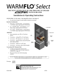
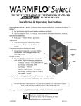
WARMFLO COMPATIBLE Downflow/Horizontal EM-WD *** 5* Width 5 = 15” 8 = 18” Number of Stages kW Size 10 = 10 kW 15 = 15 kW 20 = 20 kW 14 = 14.4 kW 3 Ph 22 = 22 kW 3 Ph 25 = 25 kW This manual provides the installation information for the mechanical and 240 power wiring of the Electro-Mate® itself. The WarmFlo control wiring is detailed within controller manual, HI320, typically shipped with the furnace interface module. Note: This model now includes 250°F manual hi-limit reset, located behind the hinged controller board door. Drawings: 12/23/2004 EC001 EA104 EA111 ES723 ES724 ES725 EI707 TABLE OF CONTENTS PAGE Description 1 Installation Requirements 1 Specifications – Table 1 2 Mechanical Installation 2 Electrical Installation 3 Grounding 3 Manual Reset 4 System Airflow 4 System Temperature Rise 4 CFM Calculation (this model) 4 CFM Calculation (oil/gas furnace) 4 Drawings 12/23/2004 EC001 EA104 EA111 ES723 ES724 ES725 UAI012 EI707 DESCRIPTION This Electro-Mate series is the supplementary electric element for air source heat pump, add-on or A-coil type. The placement of the electric elements and mechanical design of this Electro-Mate is compatible with zero clearance at the heat pump and/or A/C A-coil top. These models are approved and listed for downflow and horizontal applications. At no time can this model be installed in an upflow application. Electro Industries has a similar unit specially designed for upflow applications. The Electro-Mate must be installed on the “warm side” of the HP A-coil. Caution, Heat Pump Application: Depending upon mechanical positioning and airflow, in all cases (heat pump) the electric element, Electro-Mate, unit must be on the supply or warm side of the HP refrigerant coil. Generally, a base adapter or raised plenum is required for installation of this DOWNFLOW Electro-Mate. The instructions on page 2 for the field design and fabrication of this base adapter must be followed in detail. The controller installation manual, HI320, has additional comments on horizontal installation. This Electro-Mate unit contains several patented mechanical airflow, and electrical control features. Since these patented features cause this unit to be unique compared to other electric heating products, this installation manual must be studied and followed in detail. Attached is the product limited warranty statement. Please read and understand conditions associated with proper installation, unauthorized changes, and POWER ON procedures. For information, this unit is rated at 240VAC. When operating at lower source voltage, the output is reduced. Example: 10 kW rating 220VAC source - 8.8 kW 208VAC source - 7.5 kW INSTALLATION REQUIREMENTS 1. All installation work must be performed by trained, qualified contractors or technicians. Electro Industries, Inc., sponsors installation and service schools to assist the installer. Visit our web site at electromn.com for upcoming service schools. 2. All electrical wiring must be in accordance with National Electric Code and local electric codes, ordinances, and regulations. 3. Observe electric polarity and wiring colors. Failure to observe could cause electric shock and/or damage to the equipment. 4. This unit can only be used for its intended design as described in this manual. Any internal wiring changes, modifications to the circuit board, modifications or bypass of any controls, or installation practices not according to the details of this manual will void the product warranty, the ARL certification label, and manufacturer product liability. Electro Industries, Inc., cannot be held responsible for field modifications, incorrect installations, and conditions which may bypass or compromise the built-in safety features and controls. 5. The only approved installation for this Electro-Mate series is downflow and horizontal furnace and above or downstream from the air conditioning or heat pump A-coil. Any other configuration or furnace plenum/ducting installation voids warranty and manufacturers product liability. 12/23/2004 1 EI707 SPECIFICATIONS - TABLE 1 Model Number EM-WD1025* EM-WD153** EM-WD2045* EM-WD25458 EM-WD14358 EM-WD22478 kW rating BTUH Voltage/Phase Circuit Breaker Source Feed Elements Min. CFM Max. Temp. Rise Shipping Weight 10 34000 240/1 60 1 4 700 45°F 24# 15 51000 240/1 1-30, 1-60 2 6 1100 45°F 30# 20 68000 240/1 2-60 2 8 1400 45°F 32# 25 85000 240/1 1-30, 2-60 3 10 1700 45°F 34# 14.4 49000 208/3 50 1 6 1000 45°F 32# 22 75000 208/3 80 1 9 1500 45°F 36# MECHANICAL INSTALLATION Caution, Heat Pump Application: Depending upon mechanical positioning and airflow, in all cases (heat pump) the electric element, Electro-Mate, unit must be on the supply or warm side of the HP refrigerant coil. Depending upon application, refer to the appropriate drawing and Electro-Mate position. EA104, revision E and above – heat pump – below A-coil. EA111 – air conditioning, non-heat pump – above A-coil. ADDITIONAL HEAT PUMP COMMENTS: Since this is probably associated with a heat pump, these instructions and drawing EA104 assume a A-coil where the air is driven backwards through the A-coil. If your installation is a slant coil or a V-coil, positioning of the Electro-Mate is still the same, in the case of the V-coil you can have a much tighter installation. The 1” minimum spacing of the actual Electro-Mate front enclosure and the bottom of the drip pan is a compromise because typically vertical space is at a premium. If you can allow additional space under the drip pan, do so. For this type of installation where the air is coming out of the center hole in the drip pan, actually the use of a 15” wide Electro-Mate is preferred. This would be opposite the normal recommendation for a 15” wide unit in large plenums. However, there still should be side and end baffling even though the air is coming out of the drip pan center. In this situation there will definitely be turbulence and unpredictable flow as it comes out of the center hole. Make sure all the air is forced through the Electro-Mate elements. FURNACE TYPE - This unit must be installed in as DOWNFLOW application only. Do not turn the Electro-Mate upside down or install this unit in the cold air return. Verify that all transitions have angles less then 3Ø°, the Electro-Mate is centered within the plenum, and there are no odd shaped angles or odd shaped transitions within the plenum. If the width or depth is greater than approximately 1” of the Electro-Mate element pattern, side and back deflectors may be required. Use the same general deflector requirements and techniques normally described in the Electro-Mate upflow manual. If you are not familiar with this, request drawing EH1Ø8. For horizontal applications reference manual HI320. If the DOWNFLOW furnace is setting directly on the floor, the furnace will have to be raised for insertion of the Electro-Mate unit. This will require a field designed and constructed plenum. This plenum must have sufficient strength to carry the weight of the existing furnace. 12/23/2004 2 EI707 The Electro-Mate is designed with a special double plate at the element mounting. Cool air from the blower must blow between these two plates. Therefore, the Elector-Mate must be inserted into the base plenum such that the mounting plate is even with the edge of the hot air outlet hole. Do not necessarily line up the Electro-Mate control box with the furnace cabinet front. The concern is the hole in the bottom of the furnace mating with Electro-Mate elements. Cutting the correct hole size in the plenum – locate the supplied cutout template marked “UAI012”. Once placement of the Electro-Mate is determined, tape all four corners of the template to the plenum. Make sure that the template is squared off to the plenum before proceeding to the next step. Using a utility knife cut out the appropriate dashed line on the template. Then use a marker to trace around the area cut out of the template. Remove the template from the plenum and proceed to cut the hole into the plenum. Extend the “V” channel to butt against the plenum surface opposite the 8”x18” hole. After Electro-Mate insertion, a sheet metal screw may be installed to attach the back plate of this “V” deflector channel. Insert the Electro-Mate and properly screw to base plenum. If the base plenum is 18” wide, side supports will be needed on the side for proper attachment to the Electro-Mate. Special Hi-Limit Probe Installation Shipped loose with this unit is a hi-limit probe which must be installed under the electric elements (counterflow). This is shown on drawing EA104. This hi-limit probe must receive direct heated air from the electric elements. It is wired into the red/white hi-limit loop as detailed in the “ELECTRICAL HOOK-UP” section of this manual. WarmFlo Supply Sensor Installation Notice spacing and positioning comments on drawing EA104. Basically this sensor needs to be in a major air stream, about 20 airflow inches away from the actual electric element. ELECTRICAL INSTALLATION This manual applies only to the 240 power wiring. See WarmFlo controller manual, HI320, for all control wiring. The Electro-Mate nameplate lists the continuous amp draw for the model you are installing. Based upon NEC requirements and/or local codes, supply and route an appropriate 240VAC size cable or power wires between the electrical panel source and the Electro-Mate inside circuit breakers, use only copper connected to breakers. If you would like to feed the Electro-Mate breakers using one feed you must order the optional bus bars listed below: 15 and 20 kW models 25 kW models EM-5716 EM-5717 Grounding – route and install the appropriate size conductor wire between the Electro-Mate lug labeled “ground” and the building service entrance panel ground bus. This must be a conductor wire sized according to the total amp rating of the Electro-Mate. The conduit is not a sufficient ground conductor. 12/23/2004 3 EI707 MANUAL RESET Located behind the hinged control board door is a 250°F manual reset. This breaks the circuit for all electric elements. However, connected in the same circuit loop is the automatic reset 170°F hi-limit. Normally the automatic reset should always take care of any overheat condition prior to popping the manual reset. Therefore, you should not experience a manual reset condition unless there has been a true hardware failure. Two exceptions – a standby furnace (or wood furnace) having an outlet temperature greater than 250°F or cold startup without blower. Because of the sensitivity of this capillary manual reset, anytime there is a blower failure when the elements come on you can expect a manual reset. SYSTEM AIRFLOW Since the majority of the applications for this Electro-Mate are air source heat pumps, it is assumed the airflow is adequate for the heat pump and typically greater than required by this Electro-Mate. In any case, the very minimum airflow for this Electro-Mate is: 10 kW – 700 CFM 15 kW – 1100 CFM 20 kW – 1400 CFM 25 kW – 1700 CFM These requirements assume 85° air inlet (heat pump output). If using with A/C only, use standard Electro-Mate CFM requirements. Also follow the power up instructions in the warranty report procedure EC110. SYSTEM TEMPERATURE RISE - The overall temperature rise (both sides of Electro-Mate) must be less than 45°F. If any portion of the plenum top is operating with an air temperature greater than 125°F, element life will be shortened. 1. A. CFM CALCULATION, THIS ELECTRO-MATE - By measuring the temperature rise across the Electro-Mate, the actual CFM can be quite accurately determined. The airflow and Electro-Mate unit must be operating in a stable condition for at least 10 minutes. If it is cycling on temperature limit, this calculation will be of no value. The accuracy of this formula will depend upon uniform and average temperature rise plenum thermometer readings and the accuracy of both the clamp-on amp meter and AC voltmeter. NOTE: The volts x amps x 3.4 value is the same as Btuh output. CFM = B. CALCULATED CFM, OIL/GAS FURNACE - By measuring the temperature rise across the existing furnace, the CFM can be approximated. The accuracy of this formula will depend upon the estimated or determined Btuh output (actual heat energy across the furnace). You cannot use name plate Btuh values. You must use a realistic estimated or measured true OUTPUT Btuh. CFM = 12/23/2004 Volts x Amps x 3.4 Temperature Rise x 1.08 Btuh (output) Temperature Rise x 1.08 4 EI707 Electro Industries, Inc. Limited Product Warranty Effective February 5, 2009 Electro Industries, Inc. warrants to the original owner, at the original installation site, for a period of two (2) years from date of installation, that the product and product parts manufactured by Electro Industries are free from manufacturing defects in materials and workmanship, when used under normal conditions and when such product has not been modified or changed in any manner after leaving the plant of Electro Industries. If any product or product parts manufactured by Electro Industries are found to have manufacturing defects in materials or workmanship, such will be repaired or replaced by Electro Industries. Electro Industries shall have the opportunity to directly, or through its authorized representative, examine and inspect the alleged defective product or product parts. Electro Industries may request that the materials be returned to Electro Industries at the owner’s expense for factory inspection. The determination as to whether product or product parts shall be repaired, or in the alternative replaced, shall be made by Electro Industries or its authorized representative. Electro Industries will cover reasonable labor costs to repair defective product or product parts for ninety (90) days after installation. TWENTY YEAR (20) LIMITED WARRANTY ON BOILER ELEMENTS AND VESSELS Electro Industries, Inc. warrants that the boiler elements and vessels of its products are free from defects in materials and workmanship through the twentieth year following date of installation. If any boiler elements or vessels are found to have a manufacturing defect in materials or workmanship, Electro Industries will replace them. TWENTY YEAR (20) LIMITED WARRANTY ON SPIN FIN ELEMENTS Electro Industries, Inc. warrants that the spin fin elements of its products are free from defects in materials and workmanship through the twentieth year following date of installation. If any spin fin elements are found to have a manufacturing defect in materials or workmanship, Electro Industries will replace them. FIVE YEAR (5) LIMITED WARRANTY ON OPEN WIRE ELEMENTS Electro Industries, Inc. warrants that the open wire elements of its products are free from defects in materials and workmanship through the fifth year following date of installation. If any open wire elements are found to have a manufacturing defect in materials or workmanship, Electro Industries will replace them. Page 1 of 2 XX017 THESE WARRANTIES DO NOT COVER: 1. Costs for labor for removal and reinstallation of an alleged defective product or product parts, transportation to Electro Industries, and any other materials necessary to perform the exchange, except as stated in this warranty. Replacement material will be invoiced to the distributor in the usual manner and will be subject to adjustment upon verification of defect. 2. Any product that has been damaged as a result of being improperly serviced or operated, including, but not limited to, the following: operated with insufficient water or airflow, allowed to freeze, subjected to flood conditions, subjected to improper voltages or power supplies, operated with airflow or water conditions and/or fuels or additives which cause unusual deposits or corrosion in or on the product, chemical or galvanic erosion, improper maintenance or subject to any other abuse or negligence. 3. Any product that has been damaged as a result of natural disasters, including, but not limited to, the following: lightning, fire, earthquake, hurricanes, tornadoes or floods. 4. Any product that has been damaged as a result of shipment or handling by the freight carrier. It is the receiver’s responsibility to claim and process freight damage with the carrier. 5. Any product that has been defaced, abused, or suffered unusual wear and tear as determined by Electro Industries or its authorized representative. 6. Workmanship of any installer of the product. This warranty does not assume any liability of any nature for unsatisfactory performance caused by improper installation. 7. Transportation charges for any replacement part or component, service calls, normal maintenance; replacement of fuses, filters, refrigerant, etc. CONDITIONS AND LIMITATIONS: 1. If at the time of a request for service the original owner cannot provide an original sales receipt or a warranty card registration then the warranty period for the product will have deemed to begin thirty (30) days after the date of manufacture and NOT the date of installation. 2. The product must have been sold and installed by a licensed electrical contractor, a licensed plumbing contractor, or a licensed heating contractor. 3. The application and installation of the product must be in compliance with Electro Industries’ specifications as stated in the installation and instruction manual, and all state and federal codes and statutes. If not, the warranty will be null and void. 4. The purchaser shall have maintained the product in accordance with the manual that accompanies the unit. Annually, a qualified and licensed contractor must inspect the product to assure it is in proper working condition. 5. All related heating components must be maintained in good operating condition. 6. All lines must be checked to confirm that all condensation drains properly from the unit. 7. Replacement of a product or product part under this limited warranty does not extend the warranty term or period. 8. Replacement product parts are warranted to be free from defects in material and workmanship for ninety (90) days from the date of installation. All exclusions, conditions, and limitations expressed in this warranty apply. 9. Before warranty claims will be honored, Electro Industries shall have the opportunity to directly, or through its authorized representative, examine and inspect the alleged defective product or product parts. Remedies under this warranty are limited to repairing or replacing alleged defective product or product parts. The decision whether to repair or, in the alternative replace, products or product parts shall be made by Electro Industries or its authorized representative. THESE WARRANTIES DO NOT EXTEND TO ANYONE EXCEPT THE ORIGINAL PURCHASER AT RETAIL AND ONLY WHEN THE PRODUCT IS IN THE ORIGINAL INSTALLATION SITE. THE REMEDIES SET FORTH HEREIN ARE EXCLUSIVE. ALL IMPLIED WARRANTIES, INCLUDING WARRANTIES OF MERCHANTABILITY AND FITNESS FOR A PARTICULAR PURPOSE, ARE HEREBY DISCLAIMED WITH RESPECT TO ALL PURCHASERS OR OWNERS. ELECTRO INDUSTRIES, INC. IS NOT BOUND BY PROMISES MADE BY OTHERS BEYOND THE TERMS OF THESE WARRANTIES. FAILURE TO RETURN THE WARRANTY CARD SHALL HAVE NO EFFECT ON THE DISCLAIMER OF THESE IMPLIED WARRANTIES. ALL EXPRESS WARRANTIES SHALL BE LIMITED TO THE DURATION OF THIS EXPRESS LIMITED WARRANTIES SET FORTH HEREIN AND EXCLUDE ANY LIABILITY FOR CONSEQUENTIAL OR INCIDENTAL DAMAGES RESULTING FROM THE BREACH THEREOF. SOME STATES DO NOT ALLOW THE EXCLUSION OR LIMITATION OF INCIDENTAL OR CONSEQUENTIAL DAMAGES, SO THE ABOVE LIMITATIONS OR EXCLUSIONS MAY NOT APPLY. PRODUCTS OR PARTS OF OTHER MANUFACTURERS ATTACHED ARE SPECIFICALLY EXCLUDED FROM THE WARRANTY. THIS WARRANTY GIVES YOU SPECIFIC LEGAL RIGHTS, AND YOU MAY HAVE OTHER RIGHTS WHICH VARY UNDER THE LAWS OF EACH STATE. IF ANY PROVISION OF THIS WARRANTY IS PROHIBITED OR INVALID UNDER APPLICABLE STATE LAW, THAT PROVISION SHALL BE INEFFECTIVE TO THE EXTENT OF THE PROHIBITION OR INVALIDITY WITHOUT INVALIDATING THE REMAINDER OF THE AFFECTED PROVISION OR THE OTHER PROVISIONS OF THIS WARRANTY. Page 2 of 2 XX017