1
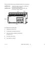
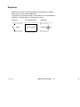
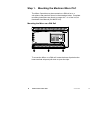
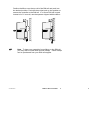
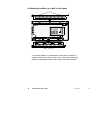
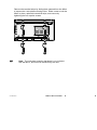
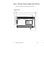
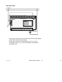
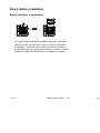
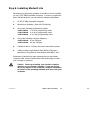
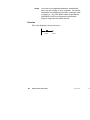
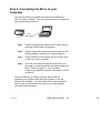
Modicon
Micro Controllers
Quick-Start Guide
GI--KWIK--ENG Rev. C
A91M.12-703570.20-1195
Breite: 151,5mm
Höhe: 227,5mm
Modicon
Micro Controllers
Quick-Start Guide
GI--KWIK--ENG Rev. B
A “Read--Me--First” Instruction
Guide for the new user, covering
A “Read-Me-First” Instruction
basic installation and wiring of
Guide for the new user,
the Model 311 Modicon Micro
covering basic installation
Controllers.
and wiring of Modicon Micro
Controllers.
GI--KWIK--ENG
Modicon Micro Quick-Start
1
1
Table of Contents
List of Materials in the Micro box
Page 3
Exercise
Page 5
Step 1.
Mounting the Micro
Page 6
Step 2.
Wiring of Power Supply and I/O Points
Page 10
Step 3.
Powering up the Micro
Page 12
Step 4.
Front Panel Indicators
Page 13
Step 5.
User Memory Options/Flash Memory
Page 14
Step 6.
Battery Installation
Page 15
Step 7.
Programming Options
Page 16
Step 8.
Installing Modsoft Lite Software
Page 17
Step 9.
Connecting the Micro to your Computer
Page 21
Where to look for additional information
Page 22
Document Control Number: 043505188
First Printing: November, 1993
Copyright ©1993 Modicon, Inc. All rights reserved.
2
Modicon Micro Quick-Start
GI--KWIK--ENG
PRE
This Quick Start Guide covers the Modicon Micro PLC Part Numbers:
110CPU31101
110CPU31102
115/230 VAC with 16 Inputs @ 115 VAC and
8 Triac and 4 Relay Outputs
230 VAC with 16 Inputs @ 230 VAC and
8 Triac and 4 Relay Outputs
Inputs
Battery
Power
Supply
Outputs
List of Materials in the Micro Box:
1.
A Modicon 311 Micro PLC
2.
A small bag of mounting accessories
3.
The 311/411 Micro Hardware User Manual
(GI--MICR--341)
4.
This Quick--Start Guide
5.
Any updates or bulletins
GI--KWIK--ENG
Modicon Micro Quick-Start
3
3
4
Modicon Micro Quick-Start
GI--KWIK--ENG
PRE
Exercise
We will show you the necessary steps and operations to make a
Micro run by a very simple application.
A light bulb connected to output 1 of the Micro is to be switched on
and off by a switch which is connected to input 1.
Input Level
I1
GI--KWIK--ENG
Switch
Logic Operation Level
Micro Program
Output Level
Light Blub
O1
Modicon Micro Quick-Start
5
5
Step 1. Mounting the Modicon Micro PLC
The Micro Controller may be mounted on a DIN rail or to a
sub-plate or flat panel as shown in the drawings below. Complete
mounting instructions are found on pages 38 -- 41 of the 311/411
Hardware User Manual (GI--MICR--341).
Mounting the Micro on a DIN Rail
To mount the Micro on a DIN rail, locate the three clips below the
lower terminal strip and pull down to open the clips.
6
Modicon Micro Quick-Start
GI--KWIK--ENG
PRE
Position the Micro over the top rail of the DIN rail and push into
the desired position. Push the three clips back up into position to
secure the controller to the DIN rail. If a 15 mm DIN rail is used
instead of a 7.5 mm rail, use the spacers shipped with the Micro.
Note To keep your controller from sliding on the DIN rail,
you may wish to install DIN rail end clamps. These clamps
can be purchased from your DIN rail supplier.
GI--KWIK--ENG
Modicon Micro Quick-Start
7
7
Or Mounting the Micro on a Wall or Sub--plate
X
X
To mount the Micro on a backplane or sub-plate, locate the 4
captive screws (X) at each corner of the input (top) and output
(bottom) removable terminal strips, and loosen these screws.
8
Modicon Micro Quick-Start
GI--KWIK--ENG
PRE
Remove the terminal strips by sliding them outward from the Micro
to expose the 4 sub-plate mounting holes. Either screw or bolt the
Micro in place, replace the terminal strips, and secure by
tightening the four captive screws.
Note The sub-plate mounting hardware is not included
with the Micro, and must be furnished by the user.
GI--KWIK--ENG
Modicon Micro Quick-Start
9
9
Step 2. Wiring of Power Supply and I/O Points
Wire power supply, switch and light bulb as follows:
115 VAC Power
L = 115 VAC
N
I1
110 CPU 311 01
O1
10
Modicon Micro Quick-Start
GI--KWIK--ENG
PRE
230 VAC Power
L = 230 VAC
N
I1
110 CPU 311 02
O1
Of course, the exercise can be done with 24 VDC power supply
and 24 VDC sensors and actuators.
In this case you have to use the Micro 311 00 or 311 03.
For details, refer to 311/411 Micro Hardware User Manual
(GI--MICR--341).
GI--KWIK--ENG
Modicon Micro Quick-Start
11
11
Step 3. Powering Up
Once you have completed Steps 1 thru 4, you are ready to supply
power to the Micro. Check again to make sure that all wiring has
been completed according to instructions, and that all terminal
screws are tight.
Caution The Micro is not fused internally! YOU
must provide fusing for all input and output points,
as well as for the power supply source. Failure to
do this could result in damage to the Micro.
Observe the following sequence when applying power to the
Micro:
12
1.
Turn ON the power supply to the Micro.
2.
Observe the LEDs as the Micro completes its internal
diagnostics.
3.
The front panel indicators marked “Power OK” and
“Ready” will illuminate.
4.
If these indicators are illuminated, proceed to Step 4
for further explanation of each indicator.
5.
If these indicators are not illuminated, remove power
and recheck your wiring to the Micro.
Modicon Micro Quick-Start
GI--KWIK--ENG
PRE
Step 4. Front Panel Indicators
Below is a list of the front panel LED indicators and what their
meanings are at FIRST TIME power up of the Micro. If your
indicators are other than those indicated below, refer to the
Hardware User Manual for specific information.
Power OK LED
Red and ON when power is applied to the
Micro, OFF when no power is present or
wiring is incorrect.
Ready LED
Amber and ON when controller is OK and
has passed internal diagnostics.
Run LED
Green and flashing at power up (not
configured), when the Micro has been put
into the “Run” mode.
Batt Low LED
Red and ON if optional battery or Battery
Capacitor is not installed, or if the lithium
battery needs to be replaced (see note in
Step 6 about Battery Options).
Comm1 LED
OFF unless Micro is connected to a
computer or Hand-held Programmer;
green and flashing when communicating
with either device.
I/O Expan. Link
OFF on power-up; solid green if link is
communicating with another Micro;
flashing green when a communications
error is detected.
Input LEDs (1 -- 16)
Red and OFF or ON, depending on
the status of the sensors attached.
Output LEDs (1 -- 12) OFF.
GI--KWIK--ENG
Modicon Micro Quick-Start
13
13
Step 5. User Memory Options and Flash
Memory
Your Modicon Micro comes equipped with nonvolatile “Flash”
memory for user ladder logic storage. If you want to save register
or state RAM memory upon power loss, you’ll need one of the two
battery options described below.
Battery Options
Available battery options are a lithium battery
(Part #110XCP98000), or a 3-day battery capacitor
(Part #110XCP99000). Both can be used for Register Memory
backup.
Caution User ladder logic programs DO NOT require
battery backup, IF ladder logic programs are stored
in nonvolatile “Flash” memory in the Micro PLC.
[Refer to your Panel Software User Manual for
instructions on how to use the “Save to Flash”
command.] However, in order to save register
memory in the event of a power failure, you will need
one of the battery options. Remember, your ladder
logic program is not automatically stored in
nonvolatile “Flash” memory -- you must intentionally
perform this step in your programming software or
with the Hand-held Programmer.
Note If you do not have a battery or a battery capacitor
installed in the Micro, the “Battery Low” indicator LED
on the front panel will illuminate, even though your ladder
logic program maybe stored in “Flash” memory.
14
Modicon Micro Quick-Start
GI--KWIK--ENG
PRE
Step 6. Battery Installation
Battery Installation or Replacement
To install or replace the Battery or Battery Capacitor, remove the
small door at the top right-hand corner of the Micro as shown in
the drawing. Locate the small, white 3-conductor connector on
the printed circuit board and plug the Battery or Capacitor into this
connector. Replace the Battery Door. Installation is complete.
GI--KWIK--ENG
Modicon Micro Quick-Start
15
15
Step 7. Programming Options
Now that you have now completed all the steps necessary to
mount, wire, and power-up the Micro, you are ready to begin
programming. Two methods of programming the Micro are
available from Modicon: the Hand-held Programmer and Modsoft
Lite software. In this section, each of these options is briefly
discussed, followed by a quick install procedure for Modsoft Lite.
Option 1. Hand-held Programmer
(Modicon Part #520VPU19200)
The Hand-held Programmer is a portable, hand-sized device
which features nonvolatile “flash” memory for bi-directional
program transport. The Hand-held is powered by the Micro or by
an A/C adapter, and lets you perform all programming functions
within the Micro. Features include convenient size, password
protection, and an LCD screen. A cable is provided with the unit
to connect the Hand-held to the Micro. An optional “transfer kit”
permits connection between the Hand-held and a computer
running Modsoft programming software. Since the Hand--held
requires in--depth explanation, refer to the Hand-held Programmer
User Manual (GM--MICR--HHP) for further details about this
product.
Option 2. Modsoft/Modsoft Lite Software
(Modicon Part #371SPU92100)
Modicon supplies programming software for the Micro with either
a full-feature version -- Modsoft -- or a package supporting the
Micro and Compact only -- Modsoft Lite -- which is discussed here.
16
Modicon Micro Quick-Start
GI--KWIK--ENG
PRE
Step 8. Installing Modsoft Lite
Modsoft Lite programming software for the Micro can be installed
on any XT/AT IBM Compatible computer. In order to program the
Micro with Modsoft Lite, you will need the following equipment:
1.
An XT/AT IBM compatible computer.
2.
Modsoft Lite Software (Part #371SPU92100).
3.
One of the following programming cables:
110XCA28201 1 m (3 ft) programming cable
110XCA28202 2 m (6 ft) programming cable
110XCA28203 4 m (12 ft) programming cable
4.
One of the following computer adapters:
110XCA20300 9--pin, DB-type
110XCA20400 25--pin, DB-type
5.
A Modicon Micro, correctly wired and connected to power.
6.
A Micro Ladder Logic Manual (GM--MICR--LDR) and a
Modsoft Lite Programmer User Manual (GM--MSLT--001).
Installation of Modsoft Lite also assumes that you have basic
computer skills, and are familiar with DOS terminology and with
your computer’s operation.
Caution Before proceeding, you should be familiar
with how your computer operates. If you are unsure
about any aspect of the computer, suspend installation
and refer to the operating manuals that came with your
computer.
GI--KWIK--ENG
Modicon Micro Quick-Start
17
17
Installing Modsoft Lite (refer to Page 13 in the Modsoft Lite
Programmer User Manual)
18
Step 1
Modsoft Lite comes with both 3 1/2” and 5 1/4”
floppy diskettes. After reading the software
licensing agreement, open the diskette package
and locate Disk 1 of the size diskette that your
computer uses. Insert this diskette into drive A
(or B, if desired) and close the drive door.
Step 2
Change to Drive A (or B) by typing at the DOS
prompt: A: [then press ENTER].
Step 3
At the DOS prompt, type: LINSTALL [then press
ENTER].
Step 4
Modsoft Lite now displays the Install screen. This
screen gives you options such as where you want to
install the software, etc. Simply read and follow the
screen instructions to completely install Modsoft Lite
on your hard drive. Modsoft Lite will prompt you
when you have successfully installed the software.
Step 5
If you have just completed the Modsoft Lite
installation, you will be in the LMODSOFT directory
of your hard drive. If you have previously installed
Modsoft Lite, you must change to the Modsoft Lite
Directory. To do this, at the DOS prompt, type: CD\
[then press ENTER]; then type: CD\LMODSOFT
[then press ENTER]. Your DOS prompt will look
something like: LMODSOFT>
Step 6
Start Modsoft Lite by typing, at the DOS prompt:
LMODSOFT [then press ENTER].
Modicon Micro Quick-Start
GI--KWIK--ENG
PRE
GI--KWIK--ENG
Step 7
Modsoft Lite will start with an intro screen, as shown.
Step 8
Press any key on the keyboard to enter the Modsoft
Lite Main Menu.
Modicon Micro Quick-Start
19
19
Step 9
You have now completed installation, and Modsoft
Lite is up and running on your computer. For specific
information on configuring your Micro controller, refer
to Pages 14 -- 21 of the Micro Ladder Logic Manual
(GM--MICR--LDR); for programming information,
begin at Page 43 of the same manual.
Exercise
This is the program you have to key in:
()
10 001
20
Modicon Micro Quick-Start
00 001
GI--KWIK--ENG
PRE
Step 9. Connecting the Micro to your
Computer
You are now ready to complete the connections between the
Micro and your computer. This is the final step prior to configuring
and programming your Micro.
COM1
Micro
Programmiergerät
Step 1
Plug the programming cable into the Comm1 port on
the lower middle section of the Micro.
Step 2
Plug the other end of the programming cable into the
DB-type adapter (either the 9- or 25-pin adapter).
Step 3
Plug the DB end of the adapter into the Comm1 port
on the rear of your computer.
Step 4
You have now made all required connections, and
are ready to communicate with and Autoconfigure the
Micro. Refer to Pages 15 -- 22 of the Micro
Ladder Logic Manual for specific information on these
operations.
All the documents you need to continue with the Micro’s
operations are included, either with the controller or with the
Modsoft Lite Software. This Quick-Start Guide was designed to
help you get up and running fast, and not to provide detailed
information about the Micro.
GI--KWIK--ENG
Modicon Micro Quick-Start
21
21
Need more information?
Please refer to the documents listed on Page 27 for in-depth
information about all aspects of the Micro controller or Modsoft
Lite software.
311/411 Micro Hardware User Manual (GI--MICR--341)
Topic
Specifications
Wiring Power
Wiring Inputs
Wiring Outputs
Battery Installation
Memory Options
Front panel LEDs
Mounting
Cable Pin--Outs
Page(s)
9 -- 10
5 -- 6
12 -- 31
32 -- 37
42
3
7
38 -- 41
46
Modsoft Lite Programmer User Manual (GM--MSLT--001)
Topic
Installing Modsoft Lite Software
Software Orientation
Main Menu Functions
Configuration
PLC Programming
Quick Keys
Modsoft Lite in MS Windows
22
Modicon Micro Quick-Start
Page(s)
13 -- 24
25 -- 42
26 -- 77
79 -- 110
135 -- 195
197 -- 200
217 -- 220
GI--KWIK--ENG
PRE
Micro Ladder Logic Manual (GM--MICR--LDR)
Topic
Micro Overview, scan, memory
Memory allocation
Memory Backup
Instruction Set
Start--up Procedures
Autoconfiguring the Micro
Instruction Set
Troubleshooting
Crash Codes
GI--KWIK--ENG
Page(s)
2 -- 3
4 -- 6
7 -- 8
11 -- 12
14 -- 15
16 -- 25
47 -- 132
137 -- 144
143 -- 144
Modicon Micro Quick-Start
23
23
Worldwide Organization Sales and Services
Groupe Schneider (Square D in USA, Telemecanique in France)
Europe
France
UK
Italy
Spain
Belgium
Switzerland
Greece
(33) 1 41 29 82 00
(44) 31 899 0456
(39) 11 22 81 111
(34) 3 484 3100
(32) 2 373 7711
(41) 31 917 333
(30) 1 80 77 703
Norway
Sweden
Finland
Denmark
Netherlands
Portugal
Ireland
(47) 6924 9700
(46) 157 65200
(358) 0 615 522
(45) 44 68 7888
(31) 23 12 4124
(351) 1 417 2978
(353) 1 627 4030
America
USA
Canada
Mexico
Brazil
Argentina
Venezuela
Columbia
Ecuador
(1) 708 397 2600
(1) 416 752 8020
(525) 686 3000
(55) 11 524 5233
(54) 1 759 9622
(582) 241 1344
(57) 1 413 9181
(593) 2 40 7373
Africa/Asia/Pacific
South Africa
Marocco
Turkey
India
Singapore
Australia
Japan
Indonesia
(27) 11 802 5272
(312) 2 99 0848
(90) 16 386 9570
(91) 11 646 7658
(65) 270 2366
(61) 2 743 7700
(81) 3 5474 4474
(62) 21 750 4406
AEG Schneider Automation
Germany
East Europe
North Asia
(49) 6182 91 2584
(49) 89 1305 485
(861) 512 5627
AEG Daimler Benz Industrie
Austria
(43) 1 277 11
For not mentionned countries the contacts are assured by the regional sales offices:
Latin America
(55) 11 524 5233
Africa and Caribbean (33) 76 57 60 60
North Asia
(861) 512 5627
South-East Asia
(65) 270 2366
CIS
(49) 89 1305 485
Middle East
(971) 48 365 81
Pacific
(61) 2 743 7700
India and
(91) 11 646 7658
adjacent countries
AEG Schneider Automation headquartered in Germany, R & D and
manufacturing sites
AEG Schneider Automation, Inc.
One High Street · North Andover, MA 01845
Tel: (1) 508 794 0800 · Fax:(1) 508 975 9010
AEG Schneider Automation GmbH
Steinheimer Str. 117 · D - 63500 Seligenstadt
Tel: (49) 61 82 81 2594 · Fax (49) 61 82 81 2860
AEG Schneider Automation, S. A.
245, route des Lucioles - BP 147 · F-06903 Sophia-Antipolis
Tel: (33) 92 96 20 00 · Fax: (33) 93 65 30 31
24
Modicon Micro Quick-Start
GI--KWIK--ENG
PRE