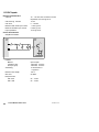
1
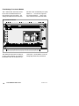
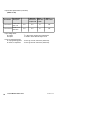
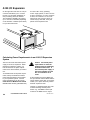
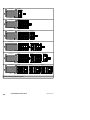
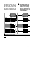
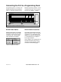
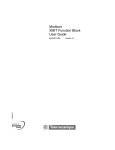
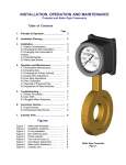
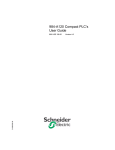
Modicon
512/612 Micro PLC
Hardware User Manual
890 USE 145 00 Ver 1.0
1
Contents
General Hardware Characteristics . . . . . . . . . . . . . . . . . . . . . . . . . . . . . . . . 3
Hardware Characteristics . . . . . . . . . . . . . . . . . . . . . . . . . . . . . . . . . . . 3
PLC Operating Modes . . . . . . . . . . . . . . . . . . . . . . . . . . . . . . . . . . . . . . 4
Memory Resources . . . . . . . . . . . . . . . . . . . . . . . . . . . . . . . . . . . . . . . . 4
Memory Backup Options . . . . . . . . . . . . . . . . . . . . . . . . . . . . . . . . . . . . 4
General Hardware Overview . . . . . . . . . . . . . . . . . . . . . . . . . . . . . . . . . . . . . 5
The I/O Terminal Blocks . . . . . . . . . . . . . . . . . . . . . . . . . . . . . . . . . . . . 5
The J1 and J2 Screws . . . . . . . . . . . . . . . . . . . . . . . . . . . . . . . . . . . . . . 6
Wiring External Power . . . . . . . . . . . . . . . . . . . . . . . . . . . . . . . . . . . . . . 6
PLC Status Display . . . . . . . . . . . . . . . . . . . . . . . . . . . . . . . . . . . . . . . . 8
Comm Ports . . . . . . . . . . . . . . . . . . . . . . . . . . . . . . . . . . . . . . . . . . . . . . 8
A120 I/O Expansion Port . . . . . . . . . . . . . . . . . . . . . . . . . . . . . . . . . . . . 9
Fixed Analog I/O in the 612 Models . . . . . . . . . . . . . . . . . . . . . . . . . 10
Base Unit Specifications . . . . . . . . . . . . . . . . . . . . . . . . . . . . . . . . . . . . . . . 12
Electrical . . . . . . . . . . . . . . . . . . . . . . . . . . . . . . . . . . . . . . . . . . . . . . . . 12
Environmental . . . . . . . . . . . . . . . . . . . . . . . . . . . . . . . . . . . . . . . . . . . . 15
Optional Hardware Part Numbers . . . . . . . . . . . . . . . . . . . . . . . . . . . 16
Partial Sampling of Available A120 I/O Modules . . . . . . . . . . . . . . . 17
Fixed I/O Specifications . . . . . . . . . . . . . . . . . . . . . . . . . . . . . . . . . . . . . . . . 18
115 VAC Inputs . . . . . . . . . . . . . . . . . . . . . . . . . . . . . . . . . . . . . . . . . . . 24
230 VAC Inputs . . . . . . . . . . . . . . . . . . . . . . . . . . . . . . . . . . . . . . . . . . . 25
24 VDC Inputs . . . . . . . . . . . . . . . . . . . . . . . . . . . . . . . . . . . . . . . . . . . 26
User-selectable High-speed Counter/interrupt Inputs . . . . . . . . . . 29
Dedicated High-speed Interrupt Inputs . . . . . . . . . . . . . . . . . . . . . . . 31
Relay Outputs . . . . . . . . . . . . . . . . . . . . . . . . . . . . . . . . . . . . . . . . . . . . 32
Triac Outputs . . . . . . . . . . . . . . . . . . . . . . . . . . . . . . . . . . . . . . . . . . . . . 35
24 VDC (FET) Outputs . . . . . . . . . . . . . . . . . . . . . . . . . . . . . . . . . . . . 37
Analog Inputs . . . . . . . . . . . . . . . . . . . . . . . . . . . . . . . . . . . . . . . . . . . . 39
Analog Outputs . . . . . . . . . . . . . . . . . . . . . . . . . . . . . . . . . . . . . . . . . . . 41
Installation Guidelines . . . . . . . . . . . . . . . . . . . . . . . . . . . . . . . . . . . . . . . . . 43
Mounting Options . . . . . . . . . . . . . . . . . . . . . . . . . . . . . . . . . . . . . . . . . 43
Installing the Optional Battery or Battery Capacitor . . . . . . . . . . . . . . . 48
Serial I/O Expansion Link . . . . . . . . . . . . . . . . . . . . . . . . . . . . . . . . . . . . . . . 49
Terminating the Link . . . . . . . . . . . . . . . . . . . . . . . . . . . . . . . . . . . . . . . 50
A120 I/O Expansion . . . . . . . . . . . . . . . . . . . . . . . . . . . . . . . . . . . . . . . . . . . . 51
Calculating Power Requirements in an A120 I/O
Expansion System . . . . . . . . . . . . . . . . . . . . . . . . . . . . . . . 51
A120 I/O Expansion Racks . . . . . . . . . . . . . . . . . . . . . . . . . . . . . . . . . 52
Connecting the PLC to a Programming Panel . . . . . . . . . . . . . . . . . . . . 56
RS-232 Cable Cables . . . . . . . . . . . . . . . . . . . . . . . . . . . . . . . . . . . . . 56
RS-232 Cable Connectors . . . . . . . . . . . . . . . . . . . . . . . . . . . . . . . . . 56
890 USE 145 00
512/612 Modicon Micro PLCs
1
General Hardware Characteristics
Hardware Characteristics
On-board CPU, memory, fixed I/O
circuitry, and power supply
16 MHz CPU speed for handling I/O
throughput
A built-in time-of-day clock
A parallel expansion port for up to
three racks of A120 I/O modules
24 VDC high-speed inputs that can
be configured to operate as dedicated hardware interrupts and/or a
user-configurable counter/timer/interrupt input
Two RS-232 ports, comm 1 and
comm 2, for communication with programming devices and with ASCII input/display devices
2
Comm 2 of 61204 (only) supports
Modbus master XMIT block. Default
condition is slave. XMIT enabled
permits port to be temporary Modbus
master ASCII or RTU mode.
Comm 1 or Comm 2 of 512xx and
612xx supports comm block, which is
Modbus master ASCII only.
An RS-485 port for serial I/O expansion with other Modicon Micro PLCs
The 612 models also support four
analog input channels and two analog
output channels.
The AC units (Models 51201 and
51202) have an on-board 24 VDC power supply that provides 150 mA. This
supply is suitable for driving the hardware interrupts or the 24 VDC I/O
points in an AC environment.
Fixed I/O
Resources
Customer Part
Number
Power
Supply
110CPU51200
24 VDC
16 (24 VDC) in
12 relay out
110CPU61200
24 VDC
16 (24 VDC) in
12 relay out
4 analog in
2 analog out
110CPU51201
115 VAC
16 (115 VAC) in
8 triac out
4 relay out
110CPU51202
230 VAC
16 (230 VAC) in
8 triac out
4 relay out
110CPU51203
24 VDC
16 (24 VDC) in
12 (24 VDC) FET out
110CPU61203
24 VDC
16 (24 VDC) in
12 (24 VDC) FET out
4 analog in
2 analog out
110CPU61204
24 VDC
16 (24 VDC) in
12 relay out
4 analog in
2 analog out
512/612 Modicon Micro PLCs
890 USE 145 00
PLC Operating Modes
The PLCs can operate in any one of
three modes:
+
--
As a single PLC—i.e., a stand-alone
programmable control system
As a parent PLC on an I/O expansion link—with the ability to access
the fixed I/O resources of the PLC(s)
in child operating mode on the link
As a child PLC whose fixed I/O
resources can be accessed by the
parent on an I/O expansion link
Note Whenever A120 I/O is
used in a child PLC, the logic
that controls the A120 I/O must
be run in the child. A parent
cannot access the A120 I/O connected to a child—it can access
only fixed I/O resources of its
children.
Memory Resources
128 kbytes of RAM
2048 words available for program
memory
2048 words of data memory
110CPU61204 PLC has 8192 words
of user data memory
Note The execution buffer is
large enough to load the XMIT
loadable or the Gas loadable
without reducing the 8K of available user logic.
Memory Backup Options
User memory—for the system configuration and application program—can be
backed up in three ways:
Using an optional (110XCP98000)
lithium battery assembly
890 USE 145 00
110XCP98000 Lithium Battery Assembly
Using an optional (110XCP99000)
battery capacitor assembly
Capacitor
Resistor
-+
Label
110XCP99000 Battery Capacitor Assembly
Writing the information to a reserved
area in the PLC’s Flash RAM
The optional lithium battery or battery
capacitor will automatically back up the
current user memory in the event of a
power shutdown. The battery can
safely back up the data for one year.
The battery capacitor can back up a
typical user logic program for 72 hr.
Note The 110XCP990000 battery capacitor must be charged in
a powered-up PLC for at least 24
hours to assure full memory backup.
The ability to back up user memory by
writing it to Flash RAM is a standard
feature of all Micro PLCs, except the
61204. Because of limitations of Flash
storage capabilities in 61204, a battery
is the only method available to backup
user memory. Memory backed up in
Flash remains completely nonvolatile
over time.
512/612 Modicon Micro PLCs
3
If you are using Flash RAM backup,
save the changes you make in your
program and/or system configuration at
the end of each edit session. The
Save to Flash command is issued from
your panel software.
Whenever PLC power is lost and then
restored, the system firmware first attempts to restore any battery-backed
memory. If there is no battery-backed
memory, then it will restore any configuration and/or programming information
stored in Flash—remember that information in Flash is only as current as the
last time you issued a Save to Flash
command. If there is no user memory
saved in Flash, the firmware will assign
the PLC a set of default configuration
parameters and no logic program will
exist.
4
512/612 Modicon Micro PLCs
890 USE 145 00
General Hardware Overview
Front View of a 512 PLC*
Terminal block for fixed discrete and hardwired inputs
Captive screw for the input terminal block
Captive screw for the input terminal block
Battery cover
PLC status display with
LED indicators
Five terminal screws for
external power connection
J1 screw for signal
ground-to-chassis ground
J2 screw for 120
of the PLC
Captive screw for the output terminal block
W termination
Captive screw for the output terminal block
Terminal block for fixed discrete outputs
* The 612 PLC has an additional set of terminal blocks for analog I/O (see page 11).
The I/O Terminal Blocks
The terminal block at the top of the PLC
provides screw terminal connections for
the 16 fixed discrete inputs and the
high-speed interrupt and counter/timer/
interrupt inputs. The terminal block at
the bottom of the PLC provides screw
terminal connections for the fixed discrete outputs (groups of relay, triac,
and/or FET outputs).
890 USE 145 00
To make field wiring easier, terminal
blocks can be removed from the PLC
base. To remove a terminal block, loosen the two captive screws on the left
and right of the block with a slotted
screwdriver until they spring free of their
mating pieces in the unit base. Then
use the screwdriver to pop the block out
of the PLC base.
512/612 Modicon Micro PLCs
5
Use a Philips #2 screwdriver to make
the field wire connections to the terminal screws, then push the terminal
blocks back on the PLC base.
The J1 and J2 Screws
Two factory-set screws are installed on
the front of the unit. The J1 screw is located below the power connectors on
the left front of the unit, and the J2
screw is located below the PLC status
display on the right front of the unit.
The position of the J1 screw in the PLC
housing determines whether there is
conventional signal ground-to-chassis
grounding or grounding at different potentials for non-grounded applications.
When J1 is fully tightened—i.e., in its
factory-set position—both signal ground
and chassis ground in the PLC are tied
together and to the input power terminal
block ground screw. This is the preferred method of grounding for all
single, parent, or child PLCs whenever
solid earth ground is available.
and damage to the PLCs or
other attached devices.
The J2 screw provides 120 W termination for the PLC when it is tightened—
J2 is shipped from the factory in a tightened position. When the PLC is
operating in single mode or when it is a
parent or child at the head or tail end of
an I/O expansion link, the J2 screw
must remain tightened. When the PLC
resides in a non-terminating location on
an I/O expansion link, the J2 screw
must be loosened by one turn.
Wiring External Power
External connections to the power supply are made at the five terminal screws
located on the left front of the PLC.
The wires from the external source are
fed to the appropriate screws through
slots along the left side of the PLC, as
shown in the following illustration.
A Left Front Isoview of the PLC
When the J1 is loosened (counterclockwise), it disconnects earth ground from
signal ground. The PLC can now be
connected as part of a non-grounded or
single-point ground system. In a singlepoint ground system, only one PLC
needs to be tied to chassis ground (J1
screw tightened); all other PLCs in the
system can be referenced to this single
point over the I/O expansion link (their
J1 screws loosened). The expansion
link must always be attached to prevent
communication errors in the ungrounded PLCs.
Caution Before you power
up your system, make sure
that all the PLCs are at the
same earth ground potential
to reduce communication errors, ground loop lockups,
6
512/612 Modicon Micro PLCs
3
2
1
1. Five terminal screws for external power wiring
2. Side slots for leading wires from the power source
to the terminal screws
3. Label indicating power wiring scheme
890 USE 145 00
The label affixed to the left front of the
PLC indicates the power wiring scheme.
Model 110CPU51200,
110CPU61200, 110CPU51203,
110CPU61204, and 110CPU61203
PLCs use a 24 VDC external power
source, wired like this:
24 VDC
Model 51202 PLCs use a 230 VAC
external power source, wired like
this:
L
1
230 VAC
2
1
3
2
N
4
3
5
24 RET
4
The labels for the power source terminal connections are in red lettering.
5
Model 11051201 PLCs use a
115 VAC external power source,
wired like this:
Note Add a wire loop between
the pins labeled JUMPER.
1
L
2
115 VAC
3
N
4
5
890 USE 145 00
512/612 Modicon Micro PLCs
7
PLC Status Display
The display panel on the front of the
Micro PLCs uses light-emitting diodes
(LEDs) to indicate the health and status
of the unit’s CPU, battery, communication ports, and fixed I/O points. The
column of LEDs on the right side of the
unit indicates PLC status:
PLC Status LEDs
LED
Function
power ok
A green LED turned ON when internal
power is OK
ready
An amber LED that is ON when the PLC
has passed its power-up diagnostics,
and remains ON as long as the PLC is
healthy
run
A green LED that is ON when the PLC
has started and is solving logic and that
flashes when the PLC has power but
cannot find a valid configuration/
operating mode
battery low A red LED that goes ON when the internal
battery needs to be replaced (Replacement should be within 14 days of the initial
LED indication.)
This LED also goes ON if a problem is
detected in the optional battery capacitor
or if the capacitor is not fully charged.
exp. link
A green LED that goes ON steadily when
valid communications occur on the I/O
expansion link, and flashes when errors
occur on the link. similar exp link
indications occur in both PLCs involved in
the communication
comm 1
A green LED that flashes when communi-cations occur on the first RS-232 port
comm 2
A green LED that flashes when communications occur on the second RS-232 port
To reference the physical I/O point to an
LED number in the display, refer to the
field wiring diagrams presented in this
book.
If the run LED on the right is flashing in
conjunction with any of the input LEDs,
an error has been detected. The pattern of the input LED flashes indicates
the nature of the error. The person programming the PLC can refer to the
Modicon Micro Ladder Logic Manual
(890 USE 146 00) for a description of
system crash codes.
Comm Ports
Two RS-232 (comm 1 and comm 2)
ports and one RS-485 (I/O exp link)
port are located on the bottom of each
unit. The RS-232 ports use eightposition RJ45 (phone jack-type) connectors. The RS-485 port uses a
six-position RJ11 (phone jack-type)
connector.
The comm ports are multi-functional,
and under the control of the system
firmware, Their capabilities are described in the Modicon Micro Ladder
Logic Manual (890 USE 146 00) and
your panel software documentation.
The array of LEDs on the left side of
the display indicates the status of the
fixed discrete I/O points on the PLC.
Each fixed input and output point lights
a number (1 ... 16 for inputs, 1 ... 12 for
outputs) with a red LED when the associated discrete point is ON.
8
512/612 Modicon Micro PLCs
890 USE 145 00
Bottom Isoview of the PLC
comm 1 (RJ45) port
comm 2 (RJ45) port
I/O exp link (RJ11) port
30-pin A120 I/O expansion receptacle
A120 I/O Expansion Port
A dedicated A120 I/O parallel expansion
port is located on the right side of the
unit. It is a 30-pin, dual-row receptacle
with locking tabs. It will accept the connector on the left side of a DTA 201 or
DTA 202 rack, which houses the A120
I/O modules.
890 USE 145 00
512/612 Modicon Micro PLCs
9
Fixed Analog I/O in the 612 Models
The 110CPU61200, 62103 and 61204
PLCs have the additional feature of
fixed analog inputs and outputs. The
analog I/O is labeled across the lower
left front of the unit assembly, the inputs
labeled 21 ... 10 from left to right and
the outputs labeled 9 ... 1 left to right.
Here is how the front of the unit looks:
Front View of a 612 PLC
The additional connectors for analog input and output channels are located on
the bottom of the unit to the left of the
10
512/612 Modicon Micro PLCs
comm ports. The illustration on the following page shows the pin positions.
890 USE 145 00
Analog inputs
21 20 19 18 17 16 15 14 13 12 11 10
Analog outputs
9
8 7
comm 1
RS-232 port
6 5 4 3
comm 2
RS-232 port
Exp. network
RS-485 port
2 1
A Bottom View of a 612 CPU Unit
Two analog connectors are provided
with the 612 PLCs—a 12-pin analog input connector and a 9-pin analog output
connector. Each pin number is displayed on the connector.
890 USE 145 00
512/612 Modicon Micro PLCs
11
Base Unit Specifications
Electrical
Input voltages
120 VAC input
230 VAC input
24 VDC input
96 ... 132 V RMS, 47 ... 63 Hz
192 ... 264 V RMS, 47 ... 63 Hz
19.2 ... 30.0 VDC
Output voltage
24 VDC output
20.5 ... 29.0 VDC @ .15 A maximum
Output ripple and noise
24 VDC output
2.5 V peak-to-peak @ 100/120 Hz maximum
Electrical immunity
ESD
IEC 801-2, level 3
Radiated EMI
IEC 801-3, level 3
Fast transient
IEC 801-4, level 2
Surge transient
IEC 801-5, level 3
Input power interrupt
AC inputs
DC inputs
< 0.5 period with no affect
< 1 ms with no affect
Ring wave
Isolation voltages
AC in to system ground
AC in to chassis ground
DC in to system ground
IEEE-STD 472 (1974)
IEC-255-4, level 3
1780 V RMS, 1 min
1780 V RMS, 1 min
500 V RMS, 1 min
Input Power Specifications
(Values in Amps)
12
512/612 Modicon Micro PLCs
890 USE 145 00
Part Number
I/O and CPU
Description
Base Unit
6 or less
Outputs ON
Base Unit
Add if
More than 6 Hand--Held
Outputs ON is Used
Add if
PAB is Used
110CPU51200 DC Relay
CPU 24V
.30
.50
.05
.125
110CPU61200 DC Relay
CPU 24V
.30
.50
.05
.125
110CPU61204 DC Relay
CPU 24V
.30
.50
.05
.125
110CPU51203 DC/DC FET
CPU 24V
.25
.27
.05
.125
110CPU61203 DC/DC FET
CPU 24V
.25
.27
.05
.125
890 USE 145 00
512/612 Modicon Micro PLCs
13
Input Power Specifications (continued)
(Values in VA)
Part Number
I/O and CPU
Description
Base Unit
6 or less
Outputs ON
Base Unit
Add if
More than 6 Hand--Held
Outputs ON is Used
Add if
PAB is Used
110CPU51201 115VAC/Triac
CPU 115V
21.0
23.1
2.1
5.25
110CPU51202 230VAC/Triac
CPU 230V
21.0
23.1
2.1
5.25
Input voltage fuses
AC inputs
DC inputs
Power for external devices
for a programming panel
for A120 I/O expansion
14
1/
4 A SB in each primary input transformer
1.6 A SB in series with the input circuit
+5 VDC @ 150 mA continuous (maximum)
+5 VDC @ 250 mA continuous (maximum)
512/612 Modicon Micro PLCs
890 USE 145 00
Environmental
Operating Temperature
0 ... 60 degrees C
Storage Temperature
--40 ... +85 degrees C
Relative Humidity
95% noncondensing
Altitude
3800 m (15,000 ft)
Shock
30 g for 11 ms, 3 pulses/axis for up to 18 pulses
Vibration
10 ... 62 Hz @ .075 mm displacement amplitude,
62 ... 500 Hz @ 1 g
Duration: 23 min @ 2 sweeps/axis on 3 mutually
orthogonal axes at a rate of 1 octave/min
Dimensions
Height (including I/O
terminal blocks):
Width:
Depth:
Weight
158.75 mm (6.25 in)
254 mm (10 in)
76 mm (3 in)
1.45 kg (3.2 lb)
Chemical Environmental
Enclosures are made of Lexan, a polycarbonate
that can be damaged by strong alkaline solutions
Agency Approvals
All models are F.M. Class I, Div. 2 approved (except for the 61204 which is
pending), and are designed to meet VDE 0160 standards
The following models are UL 508 Listed for Industrial Control Equipment and
CSA 142 Certified for process control equipment:
110CPU51200
110CPU51201
110CPU51202
110CPU61200
110CPU61203
110CPU61204
The 110CPU51203 is CSA Certified, with UL pending
CE Compliance
To maintain compliance with the European Directive on EMC (89/336/EEC),
the Micro controller must be installed in accordance with these installation
instructions.
Conformal Coating
The 61204 is available as an option with conformal coating,
(110CPU61204C).
890 USE 145 00
512/612 Modicon Micro PLCs
15
Optional Hardware Part Numbers
RS-232 communication cable assemblies
(with RJ45 connectors on both ends)
1 m (3 ft)
110XCA28201
3 m (10 ft)
110XCA28202
6 m (20 ft)
110XCA28203
RS-485 I/O expansion link cable assemblies
(with RJ11 connectors on both ends)
61 cm (2 ft)
110XCA17101
3 m (10 ft)
110XCA17102
6 m (20 ft)
110XCA17103
16
1000 ft reels of flat cable
Eight-position (for RS-232)
Six-position (for RS-485)
490NAA00010
490NAA00020
RJ45 connectors (20/box)
RJ11 connectors (20/box)
490NAD00010
490NAD00020
RJ type connector tool
RJ11 die set
RJ45 die set
490NAB00010
490NAB00011
490NAB00012
RJ11 Y--connector
110XCA10100
RJ45 adapter connections
9-pin
Premade for PC-ATs
Wire-it-yourself (male)
Wire-it-yourself (female)
110XCA20300
110XCA20301
110XCA20302
25-pin
Premade for PC-XTs
Wire-it-yourself (male)
Wire-it-yourself (female)
110XCA20400
110XCA20401
110XCA20402
Lithium battery assembly
110XCP98000
Battery capacitor assembly
110XCP99000
Spare I/O terminal strips and covers
Input (22-pin)
Output (20-pin)
110XTS00122
110XTS00120
512/612 Modicon Micro PLCs
890 USE 145 00
Partial Sampling of Available A120 I/O Modules
Discrete Input Modules
8 point 230 VAC
8 point 115 VAC
8 point 115 VAC
16 point 24 VDC (isolated)
16 point 24 VDC (non--isolated)
16 point 24 VDC Fast Response
16 point 115 VAC
AS-BDEP-208
AS-BDEP-209
AS-BDEP-210
AS-BDEP-216
AS-BDEO-216
AS-BDEP-220
AS-BDEP-218
Discrete Output Modules
4 point Relay
8 point Relay
8 point 115 VAC
8 point 24-230 VAC
16 point 115 VAC
16 point 24 VDC (isolated)
16 point 24 VDC
AS-BDAP-204
AS-BDAP-208
AS-BDAP-209
AS-BDAP-210
AS-BDAP-218
AS-BDAP-216
AS-BDAO-216
Discrete Combination Modules
8 point 24 VDC in /
4 point Relay out
8 point 24 VDC in /
8 point 24 VDC / 2 A out
Analog Input Modules
4 channel +500 mV RTD
4 channel +10 V/+20 mA
4 channel 12 bit
8 channel 12 bit RTD TC Vdc mA
8 channel 12 bit RTD Vdc mA
8 channel 15 bit TC Vdc
Analog Output Modules
2 channel +10V / +20 mA
8 channel +10 V
Intelligent Modules
4 point turbine meter/frequency
4 point high speed input
4 channel 50 kHz high
speed counter
AS-BDAP-212
AS-BDAP-220
AS-BADU-204
AS-BADU-205
AS-BADU-206
AS--BADU-21x
AS--BADU-214
AS--BADU-216
AS-BDAU-202
AS-BDAU-208
AS-BVRC-2xx
AS-BCTR-2xx
AS-BZAE-204
For more details and a complete listing of all current A120 I/O modules, see
Modicon A120 Series I/O Modules User Guide, 890USE10900 formerly
GM-A984-IOS.
890 USE 145 00
512/612 Modicon Micro PLCs
17
Fixed I/O Specifications
110CPU51200/61200 Field Wiring (under 24 VDC power)
Fixed Discrete I/O Topology
I/O Type
Number of I/O Points
24 VDC inputs
Number of Groups
16
24 VDC user-selectable
counter/interrupt
1
24 VDC dedicated
high-speed interrupts
2
2 groups of 8
1 group of 3
Relay outputs
2 groups of 4 and
4 individually isolated
12
with Source-configured 24 VDC Inputs
24 V common
Group B common
24 V common
Group A common
24 VDC
24 VDC
.16 A
Cnt/ Int
2
int
Int
1
In In In In In In In In
16 15 14 13 12 11 10 9
In
8
In In
7 6
8
7
In
5
In
4
In
3
In
2
In
1
5
4
3
2
1
24 V
.16 A
24 V
22 21 20 19 18 17 16 15 14 13 12 11 10
User-selectable
counter or
Dedicated
interrupt
interrupts Cnt/int com
9
6
Group A
24 VDC Inputs
Group B
24 VDC Inputs
Modicon 110CPU51200
110CPU61200
110CPU61204
Group D common
Group C common
Group D
Relay Outputs
Group C
Relay Outputs
20 19 18 17 16 15 14 13 12 11 10
Isolated Relay Outputs
9
8
7
6
5
4
3
2 1
3 A Fuses
Out
4A
L L
12 11
L L
10 9
L
8
L
7
L
6
L
5
L
4
Out Out Out Out Out Out Out Out
Out
12 11 10 9
8
7 6
5
4B
Note Fast-blow fuses are recommended for input and output protection.
18
512/612 Modicon Micro PLCs
Out
3A
L
3
Out
3B
Out
2A
L
2
Out
2B
Out
1A
L
1
Out
1B
890 USE 145 00
with Sink-configured 24 VDC Inputs
Cnt/ Int
2
int
Int
1
.16 A
Fuse
.16 A
Fuse
In In In In In In In In
16 15 14 13 12 11 10 9
In
8
In In
7 6
In
5
In
4
In
3
In
2
In
1
24 V
24 V
22 21 20 19 18 17 16 15 14 13 12 11 10
User-selectable
Dedicated
counter or
interrupts Cnt/int com
interrupt
9
8
7
Group B
24 VDC Inputs
6
5
4
3
2
1
Group A
24 VDC Inputs
Modicon 110CPU51200
110CPU61200
110CPU61204
Group D common
Group C common
Group D
Relay Outputs
Group C
Relay Outputs
20 19 18 17 16 15 14 13 12 11 10
Isolated Relay Outputs
9
8
7
6
5
4
3
2 1
3 A Fuses
Out
4A
24 V common
24 VDC
L L
12 11
L L
10 9
Out Out Out Out
12 11 10 9
L
5
L
4
L
3
Out Out Out Out
8
7 6
5
Out
4B
Out
3B
L
8
L
7
L
6
Out
3A
Out
2A
L
2
Out
2B
Out
1A
24 VDC
L
1
Out
1B
24 V common
Note Fast-blow fuses are recommended for input and output protection.
Note To reduce the risk that electrical noise from field I/O devices will
effect Micro operation, we recommend that a separate 24 VDC power
source be used for the field I/O. A dual power-source configuration can
also be beneficial in preventing a failure in a single field device from
shutting down power to the PLC.
Note The wiring for the analog I/O of the 612s is shown in the simplified schematics on pages 40 (for the inputs) and 42 (for the outputs).
890 USE 145 00
512/612 Modicon Micro PLCs
19
110CPU51201 Field Wiring (under 115 VAC power)
Fixed I/O Topology
I/O Type
Number of I/O Points
115 VAC inputs
Number of Groups
16
2 groups of 8
24 VDC user-selectable
counter/interrupt
1
24 VDC dedicated
high-speed interrupts
1
Triac outputs
8
2 groups of 4
4
individually isolated
1 group of 2
Relay outputs
AC Hot
AC Neutral
In In In In In In
16 15 14 13 12 11
.16A Fuse
AC Hot
AC Neutral
In In
10 9
Group A common
Group B common
Cnt/
Int
Int
1
In
8
In
7
In
6
In
5
In In
4 3
In
2
In
1
.16A Fuse
22 21
115V
20 19
18 17 16 15 14 13 12 11 10
User-selectable
+24 V out
Dedicated
counter or
interrupt
interrupt
+24 V ref*
9
8
7
Group B
115 VAC Inputs
6
5
4
3
2
1
Group A
115 VAC Inputs
115V
Modicon 110CPU51201
Group B common
Group B hot
Group A common
Isolated
Relay Outputs
Triac Group B
20 19 18 17 16 15 14 13 12 11 10
Fuses
Relay
Hot
3A
3A
Out
12B
Relay Neutral
3A
Out
11B
L
12
Out
12A
Out
10B
L
11
Out
11A
3A
9
Group A hot
Triac Group A
8
7
.8A .8A .8A .8A
6
5
4
3
2
1
.8A .8A .8A .8A
Out
9B
L
10
Out
10A
L
9
Out
9A
L
8
L
7
L
6
L
5
L
4
L
3
L
2
L
1
Out Out Out Out
8 7 6 5
Out Out Out Out
4
3
2
1
* The 24 V power supply from pins 19 and 20 in the top block provide up to 150 mA at 24 V.
Note Fast-blow fuses are recommended for input and output protection.
20
512/612 Modicon Micro PLCs
890 USE 145 00
110CPU51202 Field Wiring (under 230 VAC power)
Fixed I/O Topology
I/O Type
Number of I/O Points
230 VAC inputs
Number of Groups
16
24 VDC user-selectable
counter/interrupt
1
24 VDC dedicated
high-speed interrupts
1
2 groups of 8
1 group of 2
Triac outputs
8
Relay outputs
4
2 groups of 4
individually isolated
AC Hot
AC Neutral
AC Hot
AC Neutral
In In In In In In In In
16 15 14 13 12 11 10 9
.16 A Recommended
Group A common
Group B common
Cnt/ Int
int 1
230V
22 21
20 19 18 17 16 15 14 13 12 11 10
User-selectable
Dedicated
counter or
Interrupt
interupt
9
In
8
In In In
7 6 5
In In
4 3
In
2
In
1 .16A Fuse
8
7
4
2
1
6
Group B
230 VAC Inputs
+24 V out
5
3
Group A
230 VAC Inputs
+24 V ref
Modicon 110CPU51202
230V
Group B common
Group B Hot
Group A common
Group A Hot
Isolated Relay Outputs
Triac Group B
20 19 18 17 16 15 14 13 12 11 10
Relay Hot
3A
Out
12B
Relay Neutral
3A
Out
11B
L
12
Out
12A
3A
Out
10B
L
11
Out
11A
9
Triac Group A
8
7
.8A
.8A .8A .8A .8A
L
9
L
8
6
5
4
3
2
1
.8A .8A .8A .8A
Out
9B
L
10
Out
10A
Out
9A
L
7
L
6
L
5
Out Out Out Out
8
7 6
5
L
4
L
3
L
2
L
1
Out Out Out Out
4
3
2
1
Group B Hot
Note: Fast-blow fuses are recommended for input and output protection
890 USE 145 00
512/612 Modicon Micro PLCs
21
110CPU51203/61203 Field Wiring (under 24 VDC Power)
Fixed Discrete I/O Topology
I/O Type
Number of I/O Points
24 VDC inputs
Number of Groups
16
24 VDC user-selectable
counter/interrupt
1
24 VDC dedicated
high-speed interrupts
2
24 VDC (FET) outputs
2 groups of 8
1 group of 3
12
3 groups of 4
with Source-configured 24 VDC Inputs
24V common
+24V
24V common
+24V
Group B common
.16 A
Cnt/ Int
int
2
22 21
Int
1
Group A common
In In In In
16 15 14 13
In In In In
12 11 10 9
20 19 18 17 16 15 14 13 12 11 10
User-selectable Dedicated
Counter or
interrupts
interrupt
Cnt/int com
In
8
9
In
7
8
In
6
In
5
6
5
7
Group B
24 VDC Inputs
In In
4 3
4
3
In
2
In
1
2
1
.16 A
Group A
24 VDC Inputs
Modicon 110CPU51203
110CPU61203
Group C
FET Outputs
Group C common
Group B common
Group A common
Group C hot
Group B hot
Group A hot
Group B
FET Outputs
20 19 18 17 16 15 14 13 12 11 10
Group A
FET Outputs
9
8
1.5A
L L L L
12 11 10 9
12 11 10 9
Out Out Out Out
7
6
5
4
3
2
1.5A
L
8
L
7
L
6
L
5
8 7 6
5
Out Out Out Out
1
1.5A Fuse recommended for
each output
L
4
L
3
L
2
L
1
4 3 2
1
Out Out Out Out
Note Fast-blow fuses are recommended for input and output protection.
22
512/612 Modicon Micro PLCs
890 USE 145 00
with Sink-configured 24 VDC Inputs
24 V Common
+24 V
.16 A Cnt/ Int
int
2
Int
1
24 V Common
Group B common
In In In In
16 15 14 13
22 21
In In In In
12 11 10 9
20 19 18 17 16 15 14 13 12 11 10
User-selectable Dedicated
Counter or
interrupts Cnt/int com
interrupt
.16 A
Group A common
In
8
9
In
7
8
In
6
In
5
6
5
7
Group B
24 VDC Inputs
In In
4 3
4
3
In
2
In
1
2
1
+24 V
Group A
24 VDC Inputs
Modicon 110CPU51203
110CPU61203
Group C
FET Outputs
Group C common
Group B common
Group A common
Group C hot
Group B hot
Group A hot
Group B
FET Outputs
20 19 18 17 16 15 14 13 12 11 10
1.5A
L L L L
12 11 10 9
12 11 10 9
Out Out Out Out
Group A
FET Outputs
9
8
7
6
5
4
3
2
1.5A
L
8
L
7
L
6
L
5
8 7 6
5
Out Out Out Out
1
1.5A Fuse recommended for
each output
L
4
L
3
L
2
L
1
4 3 2
1
Out Out Out Out
Note Fast-blow fuses are recommended for input and output protection.
Note To reduce the risk that electrical noise from field I/O devices will
effect Micro operation, we recommend that a separate 24 VDC power
source be used for the field I/O. A dual power-source configuration can
also be beneficial in preventing a failure in a single field device from
shutting down power to the PLC.
Note The wiring for the analog I/O of the 110CPU61203 is shown in
the simplified schematics on pages 40 (for the inputs) and 42 (for the
outputs).
890 USE 145 00
512/612 Modicon Micro PLCs
23
115 VAC Inputs
Electrical Characteristics
ON level
ON current @ 120 VAC
OFF level
79 ... 132 VAC with a maximum source
impedance of 6.2 kW @ 60 Hz
10 mA
0 ... 20 VAC
Maximum OFF state input current
Minimum ON state input current
1.7 mA @ 20 V
6.5 mA @ 79 V
Input impedance
12 kW @ 60 Hz
Circuit Characteristics
Simplified schematic
Field
side
Logic
side
VCC
Isolation
Method
Channel-to-bus
Group-to-group
24
Opto-coupler
1780 VAC, 2 kV DC
1780 VAC, 2 kV DC
Addressing
16 discrete bits in
1 register in
Maximum wire length
100 m
Wire size
20 AWG
Response time
ON®OFF
OFF®ON
25 ... 30 ms
25 ... 30 ms
512/612 Modicon Micro PLCs
890 USE 145 00
230 VAC Inputs
Electrical Characteristics
ON level
OFF level
164 ... 253 VAC with a maximum source
impedance of 16 kW
0 ... 40 VAC
ON state input
OFF current
7 mA @ 230 VAC, 50 Hz
1.2 mA maximum @ 40 VAC
Maximum OFF state current
1.2 mA @ 40 VAC
Minimum ON state current
5.0 mA @ 164 VAC
Input impedance
33 kW @ 50 Hz
Circuit Characteristics
Simplified schematic
Field
side
Logic
side
VCC
Isolation
Method
Channel-to-bus
Group-to-group
Opto-coupler
1780 VAC, 2500 VDC
1780 VAC, 2500 VDC
Maximum wire length
100 m
Wire size
14 AWG
Response time
ON®OFF
OFF®ON
25 ... 30 ms
25 ... 30 ms
890 USE 145 00
512/612 Modicon Micro PLCs
25
24 VDC Inputs
Electrical Characteristics for Source (True High) Inputs
ON level
15 ... 30 VDC, source impedance < 1.5 kW
OFF level
0 ... 5 VDC
Minimum ON state input current
3.4 mA @ 15 VDC
Maximum OFF current
.6 mA @ 5 V
Maximum input impedance
7.8 kW when OFF
3.0 kW when ON @ 24 VDC input
Typical impedance curve
30 V
25 V
INPUT VOLTAGE
20 V
15 V
10 V
+5 V
0 mA
26
1 mA
2 mA
3 mA
4 mA
512/612 Modicon Micro PLCs
5 mA
6 mA
7 mA
8 mA
9 mA
10 mA
11 mA
890 USE 145 00
Electrical Characteristics for Sink (True Low) Inputs
ON level
Source ground to (source voltage -- 15 V)
OFF level
Source voltage to (source voltage -- 5 V)
Minimum ON state input current
3.4 mA with 20 ... 30 V source
Maximum OFF current
.7 mA with 20 ... 30 V source
Maximum input voltage
30 VDC
Maximum input impedance
7.8 kW when OFF
3.0 kW when ON @ 24 VDC
Typical impedance curve
(Tested with 24 VDC source to common pin 18)
0 Ground
+5 V
INPUT VOLTAGE
Minimum
10 V
Typical
15 V
20 V
Maximum
25 V
30 V
0 mA
Note
890 USE 145 00
1 mA
2 mA
3 mA
4 mA
5 mA
6 mA
7 mA
8 mA
9 mA
10 mA
11 mA
We recommend the use of three-wire proximity switches on these inputs.
512/612 Modicon Micro PLCs
27
Circuit Characteristics
Simplified schematic
Field
side
28
Logic
side
Isolation
Method
Channel-to-bus
Group-to-group
Opto-coupler
1780 VAC, 2500 VDC
1780 VAC, 2500 VDC
Response time
ON®OFF
OFF®ON
2 ms
2 ms
Maximum wire length
100 m
Wire size
14 AWG
512/612 Modicon Micro PLCs
890 USE 145 00
User-selectable High-speed Counter/interrupt Inputs
Electrical Characteristics
ON level
15 ... 30 VDC
OFF level
0 ... 5 VDC
Minimum ON state input
6 mA @ 24 VDC
Maximum OFF current
0.7 mA @ 5 V
Input impedance
15.8 kW when OFF
1.95 kW when ON @ 24 VDC
Current draw
12.3 mA @ 24 VDC
Typical impedance curve
25 V
INPUT VOLTAGE
20 V
15 V
10 V
+5 V
0 mA
2 mA
Note
We recommend the use of three-wire proximity switches on these inputs.
890 USE 145 00
4 mA
6 mA
8 mA
10 mA
12 mA
14 mA
512/612 Modicon Micro PLCs
29
Circuit Characteristics
Simplified schematic
Field
side
Logic
side
Interrupt/counter
5V
Com
Isolation
Method
Channel-to-bus
Group-to-group
Opto-coupler
500 VDC
500 VDC
Addressing
1 register in
Maximum cable length
50 m
Response time
OFF®ON
ON®OFF
10 ... 20 ms
10 ... 20 ms
Required cable type
Shielded twisted pair, for noise immunity
Wire size
20 AWG
Up-counter positive edge trigger
Maximum counter rate
Pulse duration
5 kHz
> 100 ms
Interrupt voltage level
30
512/612 Modicon Micro PLCs
To assure reliable system operation,
interrupt voltage must be brought from OFF
to ON and maintained ON for 350 ms
minimum—any pulse duration < 20 ms is
filtered
890 USE 145 00
Dedicated High-speed Interrupt Inputs
Electrical Characteristics
ON level
15 ... 30 VDC
OFF level
0 ... 5 VDC
Minimum ON state input
6 mA @ 15 VDC
Maximum OFF current
0.3 mA @ 5 V
Maximum input impedance
15.8 kW when OFF
1.95 kW when ON @ 24 VDC
Current draw
12.3 mA @ 24 VDC
Note
We recommend the use of three-wire proximity switches on these inputs.
Circuit Characteristics
Simplified schematic
Field
side
Logic side
VCC
Isolation
Method
Channel-to-bus
Opto-coupler
500 VDC
Maximum cable length
50 m
Required cable type
Shielded twisted pair, for noise immunity
Wire size
20 AWG
Interrupt voltage level
To assure reliable system operation, interrupt
voltage must be brought from OFF to ON and
maintained ON for 350 ms minimum—any
pulse duration < 50 ms is filtered
890 USE 145 00
512/612 Modicon Micro PLCs
31
Relay Outputs
Electrical Characteristics
Working voltage range
(for all Micro types)
24 ... 30 VDC
24 ... 250 VAC
Maximum load current
2 A/channel
Surge current
20 A for 1 cycle
VA rating
500 VA (switching)
Minimum load current
20 mA
Maximum switching rate
5 Hz
Required external fuse size
User-installed 3 A fuse—e.g. Bussman
GMA-V-3.0—in the field wiring between
the output terminal screw and the load
Caution Internal overload protection is not provided for these outputs—external fusing is required.
Derating curve
5000
4000
3000
2000
1000
120 VAC Resistive
500
3
OPERATION (x 10 )
400
300
200
100
50
20
120 VAC cos
0.1
0.2
Æ = 0.7
0.3 0.5 1
2
3
4
5
CONTACT CURRENT (A)
32
512/612 Modicon Micro PLCs
890 USE 145 00
Circuit Characteristics
Simplified schematic
Logic
side
Field
side
5V
Varistor 280 VAC
Isolation
Channel-to-bus
Group-to-group
1780 VAC, 2500 VDC
1780 VAC, 2500 VDC
Mechanical operating cycles
20,000,000
Surge withstand capability
4 kV
Response times
ON®OFF
OFF®ON
10 ms
10 ms
Maximum wire length
100 m
Wire size
One wire
Two wires
14 AWG
20 AWG
Using Relay Outputs with Inductive
Loads
The mechanical relay outputs in Micro controllers must be provided with additional
protection when connected to an inductive load. Properly suppressing inductive
loads reduces radiated noise and prolongs the life of the relay contacts. The following three figures provide examples of how to suppress various inductive loads.
Inductive
AC Load
OUTPUT
*
0.47 mf
*
50 W
115 AC
SOURCE
COMMON
*Minimum voltage rating of 200 VAC.
890 USE 145 00
512/612 Modicon Micro PLCs
33
Inductive
AC Load
OUTPUT
*
0.47 mf
*
50 W
230 AC
SOURCE
COMMON
*Minimum voltage rating of 400 VAC.
OUTPUT
Inductive
DC Load
Clamping Diode*
+
24VDC
SOURCE
--
COMMON
*Diode must be a minimum of 2A, continuous, and greater than two times the maximum rated load voltage.
34
512/612 Modicon Micro PLCs
890 USE 145 00
Triac Outputs
Electrical Characteristics
Working voltage
Continuous range
24 ... 132 VAC for the -01 Models
24 ... 250 VAC for the -02 Models
500 VAC for 1 cycle
Maximum
Frequency of operation
47 ... 63 Hz
Maximum load current
0.5 A/channel
Surge current
5 A for 1 cycle
Minimum load current
50 mA
Maximum OFF state leakage current 1.5 mA
ON state voltage drop
1.5 V
Maximum switching rate
20 Hz
Static DV/DT
300 V/ms
Required external fuse size
User-installed 0.8 A fuse—e.g., Bussman
GMA-V-.8—in the field wiring between
the output terminal screw and the load
Caution Internal overload protection is not provided for these
outputs—external fusing is required.
Derating curve
2.0
RMS current/ point
All points on with same load
Measured with PLC mounted in normal upright position.
AMPS
1.0
.75
.5
0
10
20
30
40
50
60
AMBIENT TEMPERATURE
DEGREE C
890 USE 145 00
512/612 Modicon Micro PLCs
35
Circuit Characteristics
Simplified schematic
Live
Logic
side
Field
side
Load
Varistor 280 VAC
Group Common
36
Isolation
Method
Channel-to-bus
Group-to-group
Opto-coupler
1780 VAC, 2500 VDC
1780 VAC, 2500 VDC
Response times
ON®OFF
OFF®ON
8 ms
8 ms
Maximum wire length
100 m
Wire size
One wire
Two wires
14 AWG
20 AWG
512/612 Modicon Micro PLCs
890 USE 145 00
24 VDC (FET) Outputs
Electrical Characteristics
Working voltage range
Continuous
Maximum
20 ... 30 VDC
32 V for 10 s
56 V for 1.5 ms
ON current (@ 60 degrees C)
0.5 A / channel
2 A / group
6 A total
Surge current
5 A for .5 ms @ 6 pulses / min
Minimum load current
10 mA
Maximum OFF leakage current
1 mA @ 30 V
ON state voltage drop
.4 V @ .5 A
Maximum switching rate
4 Hz inductive
Recommended external fuse size
User-installed 1.5 A fuse—e.g., Bussman
GMA-V-1.5—in the field wiring between
the output terminal screw and the load.
Note Internal overload protection is not
provided for these outputs, and external
fusing is strongly recommended.
Total current / group
2 A @ 60 degrees C
Derating curve
All outputs similarly loaded
2.0
CURRENT / AMP.
Measured with PLC mounted in normal upright position.
1.0
.5
0
12
24
36
45 48
60
AMBIENT TEMPERATURE
DEGREE C
890 USE 145 00
512/612 Modicon Micro PLCs
37
Circuit Characteristics
Simplified schematic
Field
side
+24 V Power IN
Logic side
VCC
To Load
+24 REF
38
Isolation
Channel-to-bus
Group-to-group
1780 VAC, 2500 VDC
500 VAC
Response times
ON®OFF
OFF®ON
1 ms
1 ms
Maximum wire length
100 m
Wire size
14 AWG
512/612 Modicon Micro PLCs
890 USE 145 00
Analog Inputs
Electrical Characteristics
Input channels
Number
Types
4
Current inputs, 20 mA full scale
Voltage inputs, 10 V full scale
Input ranges
+10 V, 0 ... 10 V, 4 ... 20 mA
Input filter
Single-pole low-pass,
--3 dB frequency of 10 Hz (+20%)
Input resistance
Current mode
Voltage mode
250 W (+0.1%)
> 20 MW
Input protection
Differential
Channel-to-channel
50 VDC maximum
30 VDC maximum
Over current
25 mA maximum
Common mode range
25 VDC channel-to-channel
Group Isolation
1000 VAC RMS, 1 min. maximum
(Analog inputs are isolated from analog outputs,
input power, discrete I/O, and communication
ports.)
Wire size
1 wire
2 wires
Conversion
Type
12 AWG
14 AWG
Sigma Delta
Resolution
16 bits for +10 V
15 bits for 0 ... 10 V
13®14 bits for 4 ... 20 mA
Update time
55 ms/channel if scanned > 55ms;
otherwise, 4 times the scan rate.
Differential nonlinearity
No missing codes
Repeatability
+3 counts
Accuracy (Offset, Gain, and Linearity Errors)*
Initial @ 25 degrees C
Typical
Maximum
+.025%
+0.1%
Additional drift
(0 ... 60 degrees C)
+.07%
+0.25%
*
A 250 W current-to-voltage conversion resistor contributes an additional error of +0.1%,
+ 25 ppm/degree C (for a 4 ... 20 mA input range).
890 USE 145 00
512/612 Modicon Micro PLCs
39
Input Circuit Characteristics
Simplified Schematic
Field
Connections
Jumper
Current
Input
Input 1 (+)
Sense 1
4 ... 20 mA Input 1 (--)
Input 2 (+)
Sense 2
Input 2 (--)
Voltage
Input
Input 3 (+)
Sense 3
Input 3 (--)
Input 4 (+)
Sense 4
Input 4 (--)
10
11
250
W
.1%
Analog
MUX
DC
DC
12
13
ADC
CPU
14
15
16
V REF
17
18
19
20
21
Isolation
barrier
Note:
To reduce the possibility of erroneous readings if one or more device wires become
disconnected, it is recommended that the appropriate input and sense lines be
jumpered as shown in the above illustration.
40
512/612 Modicon Micro PLCs
890 USE 145 00
Analog Outputs
Electrical Characteristics
Output channels
Number
Types
Group Isolation
2
Current outputs
Voltage outputs
1000 VAC RMS (60 Hz), 1 min. maximum
(Analog outputs are isolated from analog inputs,
input power, discrete I/O, and communication
ports.)
1000 VDC, 1 min. maximum
Current range
Loop supply voltage
Maximum
Minimum
Max loop resistance
Voltage range
Output loads
Conversion
Resolution
4 ... 20 mA
30 V
12 V
Vloop -- 7 V
= Max. R
.02
0 ... 10 V
10 mA maximum
.1 mF maximum
1 kW minimum
12 bits
Linearity errors
+.05% maximum
Differential nonlinearity
Guaranteed monotonic
Update time
10 ms/channel
Accuracy (Offset, Gain, and Linearity Errors)
Initial @ 25 degrees C
Typical
Maximum
Volt mode
0.2%
0.35% [200--350 mV]
Current mode
0.35%
0.5%
Additional drift (0 ... 60 degrees C)
Volt mode
.05%
Current mode
0.18%
0.1%
0.26%
Note Additional separate 24 VDC supplies for I/O are not required because these circuits are isolated internally. Separate supplies may be
used and can improve system performance by avoiding the interference
caused by poor power supply regulation and load transients.
Note Twisted shielded pair cable is recommended. Terminate shields
to channel return to reduce power supply switching noise.
890 USE 145 00
512/612 Modicon Micro PLCs
41
Output Circuit Characteristics
Simplified Schematic
Field
Connections
1
0 ... 10V
2
ZL
3
DC
4
DC
5
D/A
6
W
V REF
250
.1%
ZL
+
4 ... 20 mA
7
24V
8
--
9
CPU
D/A
Isolation
barrier
W
250
.1%
1 = Channel 1, Volt out
2 = Channel 1 RTN *
3 = Channel 1
4 = Voltage monitor
5 = Channel 2, Volt out
6 = Channel 2 RTN *
7 = Channel 2
8 = Voltage monitor
4 ... 20 mA output
4 ... 20 mA output
Note -- All RTN’S are common inside box. Therefore
both outputs are referenced to same point.
42
512/612 Modicon Micro PLCs
890 USE 145 00
Installation Guidelines
The Model 512 and 612 PLCs offer a
straightforward plug-and-play installation
capability.
bottom—to secure the unit to a flat surface such as a 1/4 in metal plate in a
NEMA cabinet.
To access these through-holes, remove
the I/O terminal blocks at the top and
bottom of the unit. The through-hole
locations are shown in the dimension
drawing below.
Mounting Options
A PLC (or a PLC-based I/O expansion
link) may be mounted:
In a NEMA cabinet
The four holes are counter-bored in the
housing so that the securing screws will
not touch the terminal blocks when they
are re-inserted onto the unit.
On a wall
On an EIA rack
On DIN rail
Note If The PLC uses its A120
I/O expansion capability, the unit
and its associated A120 I/O
racks must be mounted on DIN
rail.
Use M5 screws. The type and length of
the screw depends on the kind of
surface on which the units are being
mounted—e.g., a machine screw with a
minimum length of 5/8 in should be used
to mount to a 1/4 in plate.
Securing a Unit to a Flat Surface
The PLC housing contains four throughholes—two at the top and two at the
254.00 mm (10 in)
198.00 mm (7.8 in)
56.00 mm
(2.20 in)
base +
terminal
blocks
141.5 mm
(5.57 in)
158.75 mm 132.375 mm
(5.21 in)
(6.25 in)
9.125 mm
(0.359 in)
44
123.5 mm
(4.86 in)
PLC
base
17.75 mm
(.698 in)
512/612 Modicon Micro PLCs
890 USE 145 00
Unit Dimensions
76 mm
(3 in)
158.75 mm
(6.25 in)
890 USE 145 00
512/612 Modicon Micro PLCs
45
Mounting Units on DIN Rail
The PLC can be mounted on a
DIN EN 50 022 carrier rail. The DIN rail
can be attached to a flat mounting surface or hung on an EIA rack or in a
NEMA cabinet.
surface.
7.5 mm
15 mm
If the PLC uses its A120 I/O expansion
capability, the unit and the backplanes
that house the A120 modules must be
mounted on DIN rail.
Mounted DIN Rail Profiles
35 mm
DIN EN 50 022 Carrier Rail
DIN rail may have either 7.5 mm or
15 mm clearance from the mounting
If the PLC is mounted on 15 mm DIN
rail, the two spacers shipped with the
PLC and should be placed on the lower
back of the PLC, as shown below. The
spacers keep the unit flush against a
flat mounting surface and provide vibration protection.
Spacers for a PLC to
be mounted on 15 mm
DIN rail
46
512/612 Modicon Micro PLCs
890 USE 145 00
Installing a PLC on DIN Rail
Step 1 Remove the output terminal
block on the bottom of the PLC
to gain access to the three clips
shown in (1). Pull the clips
down before placing the unit on
the DIN rail.
4a
4b
1
Step 2 Place the clip on the top of the
PLC housing over the top of
the DIN rail and drop the unit
into place.
2
Spacer
Step 4 Push the three clips on the bottom of the unit up to lock the
unit onto the DIN rail, then
snap the output terminal block
back into place.
Step 5 To keep the Micro PLC assembly from sliding on the DIN rail,
we recommend that you place
a DIN rail end clamp such as
the one shown below on both
sides of the unit assembly.
3
Step 3 If the DIN rail is on a wall or a
plate, the unit will fall flush
against the surface (see 4a).
If you are using a 15 mm DIN
rail, insert the two spacers on
the lower backside of the unit
(see 4b).
End clamps such as the one above can
be ordered from your DIN rail supplier.
890 USE 145 00
512/612 Modicon Micro PLCs
47
135 mm
(5.31 in)
940 mm
(37 in)
225 mm
(8.85 in)
~ 10 mm
(.39 in)
Modicon Micro
PLC
DTA 201
Backplane
DTA 201
Backplane
DTA 201
Backplane
DIN Rail Length to Support A120 I/O Expansion on a Modicon Micro
A DIN rail must be at least 255 mm
(10.04 in) long to support a single PLC.
To support a PLC with three DTA 201
five-slot backplanes, a DIN rail needs to
be at least 940 mm (37 in) long.
39 mm (1.5 in) minimum
117 ... 195 mm
(3 ... 5 in)
Installing a PLC on DIN Rail
Below is an illustration of recommended
clearance requirements for mounting
PLCs with A120 I/O racks in an
enclosure.
100 mm
3.9 in
200 mm
7.8 in
158.75 mm
6.25 in
Plastic wire trough allowed
130 mm
5.07 in
158.75 mm
6.25 in
Input air temp < 60 degrees C
130 mm
5.07 in
Minimum Height and Length Requirements for a NEMA Cabinet Installation
48
512/612 Modicon Micro PLCs
890 USE 145 00
Installing the Optional Battery or Battery
Capacitor
Memory backup may be provided by either a lithium battery assembly
(110XCP98000) or a battery capacitor
assembly (110XCP99000).
Both assemblies include wire leads and
a 3-position feed-thru receptacle connector. They may be ordered as options from Modicon or from your local
distributor.
Installing a Battery or Battery
Capacitor Assembly
Step 1 With a slotted screwdriver, remove the battery cover from
the Micro PLC. This cover is
located on the top right corner
of the unit above the LED
panel.
Step 3 Connect the 3-position re-ceptacle connector on the
assembly to the three pins on
the printed circuit board on the
PLC beneath the battery cover.
The receptacle is keyed so that
only the correct connections
can be made with the pins.
Step 4 Place the cover back on the
PLC unit. The memory
backup assembly is now
installed and available.
Step 2 The underside of the cover has
a finger pattern that will grab
either the lithium battery or the
capacitor. Snap the desired
component into the cover:
+
-110 XCP 990 00
Battery Capacitor
installed in the
battery cover
890 USE 145 00
110 XCP 980 00
Lithium Battery
installed in the
battery cover
512/612 Modicon Micro PLCs
49
Serial I/O Expansion Link
Up to five PLCs can be interconnected
on a serial I/O expansion link. The link
contains one parent PLC and from
one ... four child PLCs.
I/O Expansion Link Characteristics
2 ... 5
Physical comm port
RS-485
Cable type
Six-position line long body
Connector type on
the cableboth ends
RJ11 male on
125 kbyte (+ )
Encoding scheme
NRZ
W
RS-485 port
RJ11
direct connect
J2 screw loosened
Child # 1
W
120
Data rate on the link
J2 screw tightened for
120
termination
Parent PLC
Number of PLCs
Termination
An I/O Expansion Link
RS-485 port
Length of link500 m (1500 ft) maximum
6 m (20 ft) minimum
The PLCs are connected to each other
on the link via their RS-485 ports. Connections are point-to-point.
Standard six-position, foil-shielded, flat
telephone cables with male RJ11 connectors on each end are used to connect the units. Three premade cable
assemblies are available:
110XCA10100
Y—connector
J2 screw loosened
Child # 2
RS-485 port
110XCA10100
Y—connector
J2 screw loosened
Child # 3
RS-485 port
110XCA10100
Y—connector
J2 screw tightened for
120
termination
I/O Expansion Link Cables
Length
Part Number
61 cm (2 ft)
110XCA17101
3m
(10 ft)
110XCA17102
6m
(20 ft)
110XCA17103
W
Child # 4
RS-485 port
The RJ11 cable plugs directly into the
RS-485 ports on the two units at the
head and tail ends of the link. All the
other units on the link use a
(110XCA10100) RJ11 Y-connector.
RJ11
direct connect
110XCA10100 Y-connector Pinouts
RJ11 Plug for the RS485 Port
1 2
3 4
5 6
The 110 XCA 101 00 Y-connector
RJ11 plug
RJ11 jacks
1 2 3 4 5 6
RJ11 Jack for the Cable
1 2 3 4 5 6
RJ11 Jack for the Cable
Pin 1 = chassis ground
Pin 2 = TXHi
37.3 mm
(1.47 in)
50
512/612 Modicon Micro PLCs
Pin 3 = TXLo
890 USE 145 00
Front of the unit
RJ11 Connector at the RS-485 Port
Back of the unit
RS-485 Port Location on the Bottom of a PLC
Serial I/O expansion establishes a
parent-child relationship between the
units on the link. One Micro PLC acts
as the parent—its I/O processor can access the fixed I/O resources of all the
child PLCs on the link, and its CPU can
perform all the logic-solving activities for
the fixed I/O resources on the link.
Each child PLC on the link must have a
unique numerical address in the range
1 ... 4.
Note It is your responsibility as
a programmer to make sure that
each child has been uniquely addressed when the system is I/O
mapped (see Modicon Micro
Ladder Logic Manual, 890 USE
146 00, and your panel software
documentation for more details).
We recommend that you set the
child PLCs to RUN mode or
power them up before the
parent.
Individual child PLCs can be disconnected from the I/O expansion link without disrupting communications between
the parent and other child PLCs as long
as the disconnection does not break the
cable link to the other child PLCs.
890 USE 145 00
Caution When a child PLC
acts as an intelligent unit on
an I/O expansion link—i.e.,
when the child uses some or
all of its fixed I/O resources
instead of giving them to the
parent—servicing of the hardware interrupts by the child
can disrupt predictable logic
solving in the parent.
Terminating the Link
120 W termination is provided by tightening the screw labelled J2 on the front
right of the PLC below the LED status
display. Units are factory-delivered with
the J2 screw tightened.
The two units on the head and tail
ends of an I/O expansion link require
termination—i.e., the J2 screws must be
tightened. All other units on the link are
not terminated—i.e., their J2 screw
must be loosened by one turn.
512/612 Modicon Micro PLCs
51
A120 I/O Expansion
On the right side of the PLC is a 30-pin
connector that allows you to connect
the unit to a secondary backplane (or
rack) containing A120 I/O modules.
This expansion capability can support
up to 15 A120 I/O modules (depending
on the modules’ combined power draw)
in up to three DTA racks.
A 512/612 PLC in any operating
mode—single, parent, or child—can use
A120 I/O expansion. If a PLC using the
A120 I/O is a child PLC on an I/O expansion link, the A120 I/O can be accessed only by that child, not by the
parent on that expansion link.
A120 I/O
tie point
Calculating Power Requirements in an A120 I/O Expansion
System
The PLC has a 250 mA internal power
supply for A120 I/O expansion. When
planning an expansion system, you
must be aware of the power requirements of the A120 modules you want to
use.
To calculate these A120 power requirements, add up the maximum internal
power draw specified for each module
in your expansion system. Internal
power specifications can be found in
A120 Series I/O Modules User Guide
890USE10900 formerly (GM-A984-IOS).
Caution All internal power
requirements for the A120
modules must be satisfied by
the Modicon Micro PLC. A
total internal power supply of
250 mA is available from the
PLC for all modules in all
racks.
A120 modules such as the BDEP 216
DC input module and the BDAP 208 DC
output module, which draw 15 mA each,
enable you to power three fully loaded
DTA 201 expansion racks.
However, in applications that use A120
modules with large internal power
draws—e.g., the BDEP 218 AC input
module or the BDAP 210 AC output
52
512/612 Modicon Micro PLCs
890 USE 145 00
module, which draw 60 mA and 88 mA,
respectively—you could expend most of
your available power with a few modules in a single DTA rack.
A120 I/O Expansion Racks
The DTA 201 backplane is 213.4 mm
wide x 142 mm high x 31 mm deep. It
has an I/O expansion ribbon cable with
30-receptacle connector on its left side
that connects it to the unit prior to it and
a 30-pin expansion connector on its
right side (the same as the one on the
PLC) that enables extension to another
backplane.
The DTA 202 backplane is 91.5 mm
wide x 142 mm high x 31 mm deep. It
also has an I/O expansion ribbon cable
with 30-receptacle connector on its left
side for connection to the unit prior to it.
It does not have a connector on its right
side—if the DTA 202 is used, it must be
the last rack in the A120 I/O expansion.
If you plan to use a DTA 202, remember that no more than one can be used
and that it can be used only in a linear
drop layout, not in a stacked (two-high)
drop layout.
Ribbon cable
connector
Ribbon cable
connector
DTA 202 Two-slot A120 I/O Backplane
30-pin A120 I/O expansion connector
DTA 201 Five-slot A120 I/O Backplane
890 USE 145 00
512/612 Modicon Micro PLCs
53
512/612 PLC
DTA 202
Rack 1
Rack 2
512/612 PLC
DTA 201
Rack 1
Rack 2
512/612 PLC
DTA 201
DTA 202
Rack 1
Rack 2
Rack 3
512/612 PLC
DTA 201
DTA 201
Rack 2
Rack 3
DTA 201
DTA 201
DTA 202
Rack 2
Rack 3
Rack 4
Rack 1
512/612 PLC
Rack 1
512/612 PLC
Rack 1
DTA 201
Rack 2
DTA 201
Rack 3
DTA 201
Rack 4
Linear A120 I/O Expansion Layouts
54
512/612 Modicon Micro PLCs
890 USE 145 00
Caution The connectors on
the BXT 201 cable are polarized and must be connected
properly—the A connector
must be attached to the rightmost unit on the top DIN rail
and the B connector must be
attached to the rightmost unit
on the bottom DIN rail.
The racks may also be stacked on two
DIN rails and connected by a BXT 201
bus extension cable. There may be either one or two racks mounted on each
DIN rail.
Only DTA 201 backplanes can be used
for A120 I/O in a stacked layout—DTA
202 (two-slot) backplanes are not
allowed.
PLC
PLC
A
A
Rack 1
DTA 201
DTA 201
Rack 1
BXT 201
DTA 201
BXT 201
B
B
Rack 2
PLC
Rack 3
Rack 3
DTA 201
PLC
DTA 201
A
Rack 1
Rack 2
DTA 201
A
Rack 1
BXT 201
DTA 201
Rack 2
DTA 201
BXT 201
B
Rack 3
Rack 4
B
Rack 4
Stacked A120 I/O Expansion Layouts
Note The rack numbers in a stacked layout are determined by the way the
rack on the right side of the lower level is connected via BXT 201 cable to the
PLC or to rack 1 above.
890 USE 145 00
512/612 Modicon Micro PLCs
55
PLC
PLC
A
Rack 1
DTA 201
A
Rack 1
BXT 202
DTA 201
BXT 202
DTA 201
B
B
Rack 2
PLC
Rack 3
Rack 2
DTA 201
DTA 201
PLC
A
Rack 1
DTA 201
A
Rack 1
Rack 2
Rack 2
BXT 202
DTA 201
B
BXT 202
DTA 201
B
Rack 3
Rack 4
Rack 3
Stacked A120 I/O Expansion Layouts
56
512/612 Modicon Micro PLCs
890 USE 145 00
Connecting the PLC to a Programming Panel
A programming panel—for example, the
520VPU19200 Hand-held Programmer*
(HHP) or a personal computer running
Modsoft programming software—can be
connected to the PLC at one of its two
RS-232 ports, comm 1 or comm 2.
RJ45 Connectors at the RS-232 Ports
Front of the unit
Back of the unit
RS-232 Port Locations on the Bottom of a PLC
RS-232 Cable Cables
RS-232 Cable Connectors
Standard eight-position, foil-shielded,
flat telephone cables with male RJ45
connectors on each end are used to
connect the units. Three premade
cable assemblies are available:
Two female D-shell adapters are available from Modicon for PLC-to-computer
connections—a (110XCA20300) 9-pin
adapter for PC-AT type computers and
a (110XCA20400) 25-pin adapter for
PC-XT type computers.
RS-232 Communications Cables
Length
Part Number
1 m (3 ft)
110XCA28201
3m
(10 ft)
110XCA28202
6m
(20 ft)
110XCA28203
These adapters come equipped with an
RJ45 jack that allows them to clip directly onto a cable assembly. Details
are shown on the following page.
* Does not support the 61204.
890 USE 145 00
512/612 Modicon Micro PLCs
57
110XCA20300
9-pin Female Adapter
Micro
PC-AT Pinouts
RJ45 Connector
pin 1
1*
pin 9
4--40 screw threads
RJ45 jack
(8x8)
9-pin D-shell
1
DCD
TXD 3
2
RXD
RXD 4
3
TXD
DSR 2
4
DTR
GND 5
5
GND
6
DSR
CTS
7
7
RTS
RTS
6
8
CTS
9
RI
chassis
ground
8
case of
the connector
* CAUTION: Pin 1 receives 5 V from the Micro
50.8 mm
(2 in)
pin 1
110XCA20400
25-pin Female Adapter
Micro
RJ45 Connector
1*
pin 1
pin 25
4--40 jack
screws
25-pin D-shell
1
RXD 4
2
TXD
TXD 3
3
RXD
CTS 7
4
RTS
RTS 6
5
CTS
6
DSR
7
GND
8
DCD
DTR
GND
RJ45 jack
(8x8)
PC-XT Pinouts
5
DSR
2
20
chassis
ground
8
1
chassis
ground
* CAUTION: Pin 1 receives 5 V from the Micro
39.6 mm
(1.56 in)
58
pin 1
512/612 Modicon Micro PLCs
890 USE 145 00
Index
Numbers
115 VAC input specifications, 24, 25
24 VDC (FET) output specifications, with
512/612, 37
24 VDC digital output
specifications, 32, 35
512 controller
A120 I/O expansion with, 51
base unit specifications, 13
fixed I/O specifications, 18
general hardware
characteristics, 3
hardware overview, 6
installation, 43
optional battery/battery
capacitor, 48
parent/child concept, 4
PLC status display, 9
serial I/O expansion link with, 49
612 controller
A120 I/O expansion with, 51
base unit specifications, 13
fixed analog I/O with, 11
fixed I/O specifications, 18
general hardware
characteristics, 3
hardware overview, 6
installation, 43
optional battery/battery
capacitor, 48
parent/child concept, 4
PLC status display, 9
serial I/O expansion link with, 49
A
A120 I/O expansion
power requirements with, 51
racks for, 52
with 512/612, 51
analog inputs, characteristics of, 39
analog outputs, characteristics of, 41
B
battery/battery capacitor,
with 512/612, 48
C
connecting PLC to a programming
panel, 55
F
fixed analog I/O, 11
I
I/O specifications
digital inputs, 24, 25, 29, 31
digital outputs, 32, 35
FET outputs, 37
input specifications
115 VAC, 24, 25
interrupt inputs, 29, 31
interrupt input specifications, 29, 31
890 USE 145 00
Index
59
O
output specifications
115/230 VAC triacs, 35
24 VDC, 32, 35
24 VDC (FET), 37
relays, 32
P
parent/child concept
with 512/612, 4
with 512/612 serial I/O, 49
R
relay output specifications, 32
S
specifications
base unit, 13
fixed I/O, 18
T
triac output specifcations, 35
60
Index
890 USE 145 00
PR