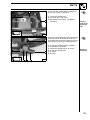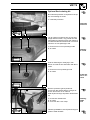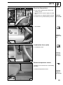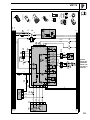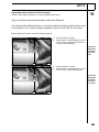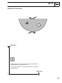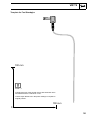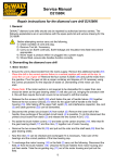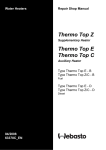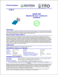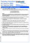
1
Air Heater Unit
Feel the drive
Air Top 2000 ST B Additional Heater
Air Top 2000 ST D Additional Heater
e1
*2001/56*0022
Installation Instructions
VW T5
Gasoline and Diesel
from Model Year 2004
For left-hand drive vehicles only
WARNING!
Hazard warning:
Incorrect installation or repair of Webasto heating systems may cause a fire or result
in the emission of carbon monoxide, which can be fatal. Serious or fatal injuries can
be caused as a result.
Specialist company training, technical documentation, specialized tools and equipment are required to install and repair Webasto heating and cooling systems.
NEVER attempt to install or repair Webasto heating or cooling systems if you have not
successfully completed the company training and thereby acquired the required technical skills, or if you do not have access to the required technical documentation, tools
and equipment needed to carry out correct installation and repairs.
ALWAYS follow all Webasto installation and repair instructions and observe all warnings.
Webasto does not accept any liability for defects and damage that are attributable to
installation by untrained staff.
Ident. No.: 9014157C_EN
Fee Euro 10
© Webasto AG
VW T5
Table of Contents
Validity
Heater Units
Foreword
General Instructions
Special tools
Explanatory Notes on the Document
General Installation Diagram
Preliminary Work
Heater Unit Installation Location
Preparing Installation Location
Preparing Heater Unit
Installing Heater Unit
Combustion Air
Fuel Connection
Metering Pump
Fuel Removal on Vehicles
without Additional or Auxiliary Heater
2
3
3
3
3
4
5
6
6
7
8
9
10
11
12
Fuel Removal on Vehicles
with Additional or Auxiliary Heater
Exhaust System
Optional Exhaust Muffler
Optional Hot Air System
Optional Recirculating Air
Electrical Connections
Optional Combination Timer
External Temperature Sensor
Remote Option (Telestart)
Fault Code Deactivation
Final Work
Operating Instructions for End Customer
Template for Fuel Sender
Template for Fuel Standpipe
14
15
15
16
19
20
20
20
21
26
27
28
29
30
13
Validity
Manufacturer
Model
Type
EG-BE No./ABE
Volkswagen
Transporter
T5
L148
Foreword
These installation instructions apply to VW T5 vehicles with a Gasoline and Diesel engine (van with
partition wall) from model year 2004 and later, assuming technical modifications to the vehicle do not
affect installation, any liability claims excluded.
Vehicles and equipment variants, which are not listed in these installation instructions, have not been
tested. However, installation according to these installation instructions may be possible. Depending
on the version and the equipment variants of the vehicle, changes may be necessary relative to these
"installation instructions" during installation and must be adjusted accordingly.
However, where this is the case the stipulations in the "installation instructions" and "operating and
maintenance instructions" for the Air Top 2000 ST should be observed.
The installation location of heater controls and the routing of the air ducting parts must be coordinated
with the final customer prior to installation!
WARNING!
Original load-bearing components of the vehicle and/or component used for crash safety may not be
modified for the hot air and recirculating air ducting!
General Instructions
Installation should be carried out according to the general, standard rules of technology. Unless specified otherwise, fasten hoses, lines and wiring harnesses to original vehicle lines and wiring harnesses
using cable ties.
Sharp edges should be fitted with edge protectors (split-open plastic hose).
Spray unfinished body areas, e.g. drilled holes, with anti-corrosion wax (Tectyl 100K, Order No.
111329).
2
VW T5
Heater Units/Installation Kit
Quantity
1
1
1
1
1
Description
Order No.:
Standard Delivery Scope Air Top 2000 ST Gasoline
Standard Delivery Scope Air Top 2000 ST Diesel
Comfort Delivery Scope Air Top 2000 ST Gasoline
Comfort Delivery Scope Air Top 2000 ST Diesel
Installation kit for VW T5 Gasoline and Diesel
9008324C
9008321C
9008325C
9008322C
9014156A
The installation kit contains the bracket with fastening parts.
The required air ducting parts must be ordered as an option from the Webasto Accessories Catalog in
accordance with the customer order!
To be ordered as an option for vehicles without factory-installed additional heater:
Quantity
1
Description
Fuel standpipe
Order No.:
1300823B
To be ordered as an option for vehicles with factory-installed additional heater:
Quantity
1
Description
6x5x6 mm fuel standpipe
Order No.:
1310367A
To be ordered as an option when using fresh-air mode:
Quantity
1
Description
External temperature sensor
Order No.:
9005004B
To be ordered as an option when using Telestart:
Quantity
1
Description
Bag for retrofitting T80
Order No.:
9014433B
The materials used for this application example - in accordance with validity on page 2 - are contained
in the following list. In case of deviations in accordance with the customer order, the materials actually
required can be ordered from the currently valid Webasto Accessories Catalog.
Quantity
1
1
5
1
1
1
1
Description
Flexible tube PAK, inside dia.= 60 mm (cut to length)
Flexible tube PAK, inside dia.= 55 mm (cut to length)
Clamp, 50-70 mm dia.
Air outlet, D1a = 60 mm; D2a = 92 mm; L = 65 mm
Air outlet, D1a = 55 mm; D2a = 87 mm; 45°
Distributor with butterfly valve, outside dia.. = 55 mm; L = 95 mm
Reducing piece, D1a = 60 mm; D2a = 55 mm; L = 35 mm
Order No.:
398497
441376
139645
87389A
107836
101374
29852A
Special tools
- Torque wrench for 2.0 - 10 Nm
- Metric thread-setter kit
- Blind rivet tool
3
VW T5
Explanatory Notes on Document
To provide you with a quick overview of the individual working steps, you will find an identification mark
on the outside top right corner of the page in question.
Mechanical system
Electrical system
Hot air system
Fuel connection
Exhaust system
Combustion air
Special features are highlighted using the following symbols:
Specific risk of injury or fatal accidents.
Specific risk of damage to components.
Specific risk of fire or explosion.
i
Reference to general installation instructions of Webasto components or to the manufacturer's vehicle-specific
documents.
Reference to a special technical feature.
The arrow in the vehicle icon indicates the position on
the vehicle and the viewing angle.
4
VW T5
General Installation Diagram
Digital timer:
comfort accessory
Not with TRS!
Installation diagram for
AT 2000 ST
Fuel filter:
option
Jumper
Terminal 15
0.75 mm²
sw
Terminal 30
1.0 mm²
Terminal 58
rt
0.75 mm²
gr
0.75 mm²
br
Terminal 31
1.0 mm²
br
0.5 mm²
sw
0.5 mm²
bl
Connection diagram for
comfort
digital timer
0.5 mm²
rt
0.5 mm²
ws
5
VW T5
Preliminary Work
WARNING!
-
Disconnect the battery "earth" or "ground" connection.
Copy the factory number from the original type label to the duplicate type label.
Remove years that do not apply from the duplicate label.
Attach the duplicate label (type label) in the appropriate place.
Open fuel tank cap, ventilate tank.
Close the tank cap again.
Remove the underbody protection on the right and left (if present).
Remove the fuel tank (only on vehicles without installed auxiliary or additional heater).
Remove the fuel-tank sending unit in accordance with the manufacturer's instructions (only on vehicles without installed auxiliary or additional heater).
- Remove the trim on the front passenger side entrance (only with recirculating air mode).
- Remove the lower instrument panel trim on the driver's side.
Heater unit installation location
1
1 Heater unit
Installation location
1
6
VW T5
1
Preparing installation location
1
1 Rivet nut (2x) in existing holes
Installing
rivet nuts
2
1
2
2 Bracket
1 M6x20 bolt, large diameter washer on rivet
nuts
1
7
Loosely
mount
bracket
3
1
1 Copy hole pattern [2x] to door sill
2 Remove bracket, drill 9.1 mm dia. hole; install rivet nuts
1
Copying
hole pattern
2
4
7
VW T5
Preparing heater unit
1
With fresh-air mode, an underride protection
as shown in Figure 33 must be installed if not
present!
3
2
1 Heater unit
2 Mount base seal
3 Protective grill
Preparing
heater unit
5
1
2
3
Cut approx. 360 mm off 60 mm dia. flexible
tube.
4
3
4
1
2
Heater unit
Wiring harness
60 mm dia. flexible pipe, 360 mm long
50-70 mm dia. hose clamp
Premounting heater
unit
6
1
Route through wire of metering pump 4
downward.
Fasten hot-air flexible tube on bracket with
cable tie.
2
3
3
4
1 Bracket
2 Large diameter washer, spring lockwasher,
M6 nut [4x each]
3 Mount edge protection, 70 mm long [2x]
5 Cable tie
Installing
bracket
7
5
1
2
1 Exhaust pipe, hose clamp
2 P-clamp, 10 mm spacer sleeve, M6x20
bolt, flanged nut
4 Combustion-air intake pipe, 27 mm dia.
hose clamp
3 Protective cap
5 Mecanyl fuel line, hose section, 10 mm dia.
hose clamp [2x]
3
5
4
Installing
lines
8
8
VW T5
1
2
Installing heater unit
1
2 Preassembled heater unit
1 M6x20 bolt, spring lockwasher, flanged nut
[2x each]
Installing
heater unit
9
1
2
2
1 Preassembled heater unit
2 M6x20 bolt, spring lockwasher, flanged nut
[2x each]
Installing
heater unit
10
9
VW T5
1
2
Combustion air
1
i
Shape combustion-air intake pipe as shown
in picture.
2 Combustion-air intake pipe
1 Cable tie
Installing
intake pipe
1
11
10
VW T5
Fuel Connection
CAUTION!
Open the vehicle's fuel tank cap, ventilate the tank and then re-close the tank lock.
Catch any fuel running off with an appropriate container.
Install fuel line and metering-pump wiring harness so that they are protected against stone impact. Unless specified otherwise, always fasten using cable ties.
Mount the fuel line and wiring harness with rub protection on sharp edges.
WARNING!
The fuel line and wiring harness are routed to the metering pump in as shown in the wiring harness
routing diagram.
Complete connector with single wire seal
[2x], tab connector and connector housing on
wire of metering pump from heater unit and
connect to wiring harness of metering pump.
1
1 Plug connection on wiring harness of metering pump
Connecting wiring
harness of
metering
pump
12
Cut heat protection hose as shown in Figure
12 and 13. Pull wiring harness of power supply and wiring harness of metering pump and
Mecanyl fuel line into one heat protection
hose each.
1
4
2
3
1 Wiring harness of power supply in heat
protection hose
2 Mecanyl fuel line and wiring harness of
metering pump in heat protection hose
3 Cable tie
Installing
lines
13
1
Route wiring harness of power supply and
wiring harness of metering pump and Mecanyl fuel line over heat guard plate on left-hand
side of vehicle. Route wiring harness of power supply further to battery.
2
4
4 Wiring harness of power supply in heat
protection hose
2 Mecanyl fuel line and wiring harness of
metering pump in heat protection hose
3 Wiring harness of power supply
1 Cable tie
3
Installing
lines
14
11
VW T5
1
2
3
Metering pump
4
Cut Mecanyl fuel line to length at installation
location of metering pump.
6
2
5
1
4
6
4
3
Ensure proper installation position of metering pump, see "Installation Instructions“.
Installation location on left on strut before vehicle fuel tank!
2
3
2
3
4
1
i
Preassembled metering pump
Flanged nut on silent block in existing hole InstallaOriginal vehicle strut
tion locaRemaining end of Mecanyl fuel line
tion of
metering
pump
16
4
Fuel line from heater unit on pressure side of
metering pump [side with connector].
1
2
3
Preassembling metering
pump
15
5
1
Metering pump
Rubber-coated pipe clamp
Silentblock, flanged nut
Hose section, 10 mm dia. hose clamps [2x]
Hose section, 10 mm dia. hose clamp
Remaining end of Mecanyl fuel line
Hose section, 10 mm dia. hose clamps [2x]
3 Preassembled metering pump
1 Wiring harness for metering pump, singlewire sealing [2x], tab connector, connector
housing
2 Fuel line from heater unit, 10 mm dia. hose
clamp on premounted hose section
Connecting metering pump
17
12
VW T5
Fuel Removal on Vehicles without
Additional or Auxiliary Heater
1
Remove fuel tank according to manufacturer's specifications. Remove fuel-tank sending
unit according to manufacturer's specifications.
Cut out template and lay on.
2
3
1 Fuel-tank sending unit
2 Template
3 Copy hole pattern, 6 mm dia. hole
Removing
fuel
18
Shape fuel standpipe according to template,
cut to length and install, see "installation instructions".
i
1
2 Fuel-tank sending unit
1 Fuel standpipe
1
Installing
fuel standpipe
2
19
1
Install fuel-tank sending unit according to
manufacturer's specifications.
2
1
2
5
3
4
5
Fuel tank
Fuel-tank sending unit
Fuel standpipe
Remaining end of Mecanyl fuel line
Hose section, 10 mm dia. Caillau clamp
[2x]
Connecting fuel
line
3
20
4
Clip fuel line from fuel standpipe 3 into existing fastening points 2.
Remount fuel tank.
1
1 Fuel tank
3 Remaining end of Mecanyl fuel line
2 Fastening points [3x]
Installing
fuel line
2
2
3
2
21
13
VW T5
1
Fuel Removal on Vehicles with
Additional or Auxiliary Heater
1
Cut off fuel line to additional or auxiliary heater as shown.
Mount fuel standpipe in cutting point as
shown.
4
3
2
22
1 Fuel line to additional or auxiliary heater
2 Fuel standpipe, 10 mm dia. hose clamp
[2x].
4 Remaining end of Mecanyl fuel line from
metering pump
3 Hose section, 10 mm dia. hose clamp [2x]
Removing
fuel
14
VW T5
1
Exhaust system
2
Align exhaust pipe as shown.
Drill 2 mm dia. condensed-water drain hole at
lowest point in exhaust pipe.
Ensure sufficient distance to neighboring
components.
1 Exhaust pipe
2 P-clamp, 10 mm spacer sleeve, self-tapping screw
Fastening
exhaust
pipe
23
Optional Exhaust Muffler
1
Installation of exhaust muffler as shown in
Figure 26 is not possible on a vehicle with underride protection equipment!
1 Exhaust pipe
2 Underride protection
Exhaust
muffler
24
2
Remove p-clamp at position 2 again.
1 Exhaust pipe
2 P-clamp
Removing
p-clamp
2
1
2
25
1
3
Cut off exhaust pipe as shown in Figure and
mount muffler.
2
1 Exhaust pipe
5 Angle bracket, M6x20 bolt, flanged nut on
bracket
3 Exhaust muffler, M6x20 bolt, flanged nut
on angle bracket
2 Hose clamp [2x]
4
1
Installing
muffler
26
15
VW T5
Optional Hot Air System
WARNING!
The routing of the air ducting parts shown is an application example on the van with a partition wall. Should
other versions and equipment variants be used, then the appropriate adjustments must be made.
Before installation, the routing of the air ducting parts must be coordinated with the end customer!
Install flexible tubes so that they are kink-free. Unless specified otherwise, always fasten using brackets and cable ties.
The hot air ducting on this version example is executed as shown in the following diagram:
6
4
5
2
3
8
1
Diagram
for hot air
ducting
7
3 = Dia. 55x60 mm adapter 5 = Air distributor 7 = Flexible tube, 60mm dia.
1 = Heater unit
2 = Flexible tube, 60 mm dia. 4 = Flexible tube, 55 mm dia.6 = Air outlet
8 = Air outlet
16
VW T5
Optional Hot Air System
1
Fold back cover under front passenger seat.
Lay on dia. 55x60 adapter as shown.
2
2 Dia. 55x60 mm adapter
1 Copy hole pattern, 60 mm dia. hole
Hole under
front passenger
seat
27
Mount adapter in hole from above and glue in
with Sicaflex.
1
1 Dia. 55x60 mm adapter
Gluing in
adapter
28
1
Mount 60 mm dia. flexible tube on adapter.
Route wiring harness of controls through protective rubber plug into passenger compartment.
2
4
1
3
2
3
4
60 mm dia. flexible pipe, 360 mm long
50-70 mm dia. hose clamp [2x]
Wiring harness of controls
Protective rubber plug
Pass
throughs
into passenger
compartment
29
55 mm dia. hole at position 2 in partition wall.
Mount air outlet and fasten with blind rivets.
1
1 Partition wall
2 Air outlet
Hole in partition wall
2
30
17
VW T5
Cut 55 mm dia. flexible tube 1 to length as
shown and mount on adapter 3.
1
3
2
1 55 mm dia. flexible tube
3 50-70 mm dia. hose clamp
2 Bracket with hose clamp, self-tapping
screw [2x]
Routing
under front
passenger
seat
31
1
6
2
5 4
3
Cut 55 mm dia. flexible tube 3 and 5 to length
as shown. Mount air distributor as shown.
Air outlet must be aligned so that hot air is not
directed at controls (e.g. handbrake lever)!
1
4
3
5
2
6
55 mm dia. flexible tube from Adapter
Air distributor, adjustable
55 mm dia. flexible tube to air outlet
55 mm dia. flexible tube
Air outlet
End cap
Mounting
distributor
32
18
VW T5
Optional Recirculating Air
No underride protection is required for the option recirculating air mode!
1 Underride protection
Underride
protection
33
1
1
Lay air outlet on entrance trim on front passenger side as shown; copy inside dia. and
hole pattern for fastening [3x] to trim. Remove
air outlet and drill 60 mm dia. hole in trim and
entrance on front passenger side.
2
1 Entrance trim on front passenger side
2 Air outlet
Installing
air outlet
34
1
Hole for fastening air outlet [3x] in trim.
Mount air outlet in trim and fasten with blind
rivets.
2
1 Entrance on front passenger side
2 Air outlet
60 mm dia.
hole in entrance
35
1
Remove protective grill at position 3.
Cut 60 mm dia. flexible tube 1 to length as
shown and mount on air outlet 3.
Seal off pass through at position 2 with Sicaflex.
2
1 60 mm dia. flexible tube
2 Air outlet
3 50-70 mm dia. hose clamp
3
36
Installing
intake
hose
Following installation, seal off pass through at
position 2 with Sicaflex.
19
VW T5
1
2
Electrical Connections
3
4 Fuse holder retaining plate, M4x12 bolt,
washer, M4 nut
1 Wiring harness of power supply for heater
unit
2 Ground wire on negative battery terminal
3 Positive wire on positive battery terminal
Installing
fuse holder
4
37
1 Thermostat
1
i
Installing
heater control
38
Combination timer option
1
i
1 Combination timer
Installing
combination timer
39
External temperature sensor
1
Installation is not carried out in recirculating
air mode!
1 External temperature sensor
Installing
temperature sensor
40
20
VW T5
Remote option (Telestart)
1
i
Connect receiver for Telestart as shown in
wiring diagram.
2
1 M5x16 bolt, flanged nut on existing hole
2 Telestart
3 Telestart bracket
Installing
receiver
41
3
Only applies for combination of standard
heater control with Telestart!
Connect switch as shown in wiring diagram.
1
1 Standard heater control
2 Switch
Installing
switch
2
42
1 Antenna
1
Installing
antenna
43
Only with Telestart HTM 100
1
1 Fasten temperature sensor with doublesided adhesive tape
Installing
temperature sensor
44
21
2
1
ws
bl
sw
rt
S9
rt
br
2
11
10
12
13
X6
A1
rt
1
M1
M
br ge
E
3
br
X2
1
2
3
rt
rt
2
ge
B1
8
X8
B4
2
br
ϑ
1
Y1
bl
sw/bl
1
1
2
X4
8
ϑ
ge
9
X6
B2
7
sw
R1
2
ϑ
br
1
15
3
sw
X8
br
2
X5
14
S6 1
5
br
X1
F2
F1
2
B3
X10
bl
1
4
16
X6
17
9
3
4
S5
ϑ
bl
2
A2
X3
5 6
2
X11
sw/rt
85
86
S4
ws/rt
31
H1
4
3
X9
T80
gn/ws
S1
30
15
M
87
F3
M3
0
30
31
1 2
K
87a
7
3
30
15
1
2
2
3
4
2 1
1
2
2 1
X11
1
X9
X10
2
1
X8
X6
X2/X3/X4/X5
X1
VW T5
i
ws/sw
System
wiring diagram with
heater control and vehicle fan
sw
br
22
X12
9
6
8
2
ws
bl
rt
sw
rt
T80
br
br
2
11
10
13
12
rt
1
A1
X6
M1
M
br ge
E
3
br
X2
3
2
rt
X1
1
F1
2
ge
B1
8
X8
B4
2
br
ϑ
1
Y1
bl
sw/bl
1
1
2
X4
8
9
X6
B2
ϑ
7
ge
R1
2
ϑ
br
1
15
3
sw
X8
br
2
X5
14
S6 1
5
sw
S7
4
H3
11
F2
2
B3
X10
bl
1
4
3
16
X6
17
9
4
S5
ϑ
bl
2
A2
X3
5 6
2
X11
sw/rt
85
86
S4
ws/rt
31
7
H4
10
6
br
12
P
1
1
gn/ws
H5
30
15
58
M
87
F3
M3
0
30
31
1 2
K
87a
7
3
30
15
58
3
1
2
6
2
9
1
2
2 1
X11
X10
X8
X6
12
X12
2
1
1
X2/X3/X4/X5
X1
VW T5
i
ws/sw
System
wiring diagram with
combination timer,
Telestart
and vehicle
fan
sw
gr
23
VW T5
1
With positive wire from terminal (15/75) to connection 10:
Continuous operation with immediate heating as long as ignition is switched on
Without positive wire on connection 10:
Heating time is variably programmable (10 min. to 120 min.), default setting is 120 min.
2
K-wire diagnosis
3
W bus
4
Input pin (Pin 16/Connector X6, wire color on wiring harness: white/red (ws/rt)):
"Ventilate“ (fan speed is dependent on position of heater control)
5
CO2 setting (see workshop manual)
6
NOTE:
If a connection is made to Terminal 30, continuous heating operation is possible with ignition
switched off! In this case, no connection may be made to Terminal 15/75!
7
Fuse present in vehicle
8
If an external temperature sensor (B4) is used, then the resistor R1 is replaced with the temperature sensor (B4)
9
Connection only for ADR vehicles
10
NOTE:
Gray (gr) and violet (vi) wires required for ADR function
11
Stop signal for battery isolator switch. The stop input (if present) of the isolator switch (S2) must
be connected to the control unit, Pin 15/Connector X6
Wiring Colors
Legend for
Wiring Diagrams
Wiring Cross-Sections
rt
gr
red
gray
0.5
sw
black
br
brown
gn
< 7.5 m
7.5 - 15 m
mm2
0.75 mm2
0.75 mm2
1.0 mm2
1.0
mm2
1.5
mm2
green
1.5
mm2
2.5 mm2
bl
blue
2.5 mm2
4.0 mm2
ge
yellow
4.0 mm2
6.0 mm2
or
vi
ws
orange
violet
white
Legend for
Wiring Diagrams
24
VW T5
Pos. Name
Remarks
A1
A2
B1
B2
B3
B4
E
F1
F2
F3
H1
H3
Heater unit
Control unit
Flame detector
Temperature sensor
Overheating sensor
Temperature sensor
Glow element
24 V 15 A/12 V 20 A fuse
Fuse, 3 A
25 A fuse
LED, green (in Pos. S1)
LED, red (in Pos. P)
Air Top 2000 ST
H4
H5
H6
K
M1
M3
P
R1
S1
S2
S3
S4
S5
S6
S7
S8
S9
V1
V2
X1
X2
X3
X4
X5
X6
X7
X8
X9
X10
X11
X12
Y1
Y2
Heating symbol in display (in Pos. P)
Lamps (in Pos. P)
Lamp (at least 1.2 W)
Relay with freewheeling diode
Engine
Engine
Combination digital timer (1531)
Resistor 620 Ω
Heater control
Isolator switch, 1 or 2-pin
Switch
Switch
Switch
Switch
Momentary-contact switch
Battery isolator switch
Additional switch
Diode
Diode
Plug connection, 2-pin
Plug connection, 2-pin
Plug connection, 2-pin
Plug connection, 2-pin
Plug connection, 2-pin
Plug connection, 2-pin
Plug connection, 12-pin
Plug connection, 2-pin
Plug connection, 4-pin
Plug connection, 2-pin
Plug connection, 2-pin
Plug connection, 12-pin
Metering pump
Solenoid valve
Only on gasoline unit
Internal
Overheating protection
External
Blade fuse, SAE J 1284
Blade fuse, SAE J 1284
Blade fuse, SAE J 1284
Operation indicator
Lighting for immediate heating button, ready display, switch-on check
Operation indicator
Display and button lighting
Switch-on check for feed device
For vehicle fan
Combustion and hot air fan
Vehicle fan
Digital timer and setpoint encoder
Only with internal temperature sensor
Setpoint encoder switch
Emergency-Stop-switch
On and for feed device
Ventilation
Rollover sensor
CO2 setting
Immediate heating button on remote control
Legend for
Wiring Diagrams
Telestart switch-off function
At Pos. A2 (ST B)
At Pos. A2 (ST V)
At Pos. A2 (ST U)
At Pos. A2 (ST Z)
At Pos. A2 (ST Y)
At Pos. A2 (ST X)
At Pos. A2 (ST1)
At Pos. S1
At Pos. Y1
At Pos. P
For feed device
25
VW T5
Shut-down on fault
Faults in individual heater unit components and malfunctions during the entire operation are recognized in the control unit.
The heater unit is shut down (fault lock-out) if:
-
No or faulty start-up
Temperature sensor defective
Open or short circuit in overheating sensor
Overheating sensor mounted incorrectly
Break or short circuit in glow element
Fan motor overloaded, blocked, short circuit or open circuit
Fault in metering pump circuit or overheating protection (only during start-up phase)
Undervoltage < 10.5 V or overvoltage >16 V and longer than 20 sec. (on heater unit with 12 V)
Undervoltage < 21 V or overvoltage >32 V and longer than 20 sec. (on heater unit with 24 V)
Control unit defective
Overheating
Flame detector (only on gasoline heater units)
In case of overheating, the fuel feed is interrupted. A run-on is carried out as with manual shut-down.
Following the run-on, the heater unit is in the fault lock-out mode. The overheating is indicated by the
operation indicator flashing 10 times.
Eliminate fault cause.
For fault release, briefly switch the heater unit off and then on again (at least 2 sec.).
If serious malfunctions, such as overheating, or no start-up occurs increasingly frequently, then the
heater unit is permanently locked (F12 or F13) and can only be returned to operation following repairs
by specially trained Webasto experts.
Fault code output:
Note:
When equipped with a heater control, fault code output is carried out after a malfunction occurs by the
switch-on check/fault code display flashing. After 5 rapid flashing pulses, the fault code output is carried
out with a sequence of long flashing pulses in accordance with the numbers in the table below. When
equipped with a combination timer, a fault output appears in the display of the digital timer after a fault
occurs. When using the heater control, the fault number is indicated by the operating indicator lamp
flashing:
Display
Fault Code
F00
F01
F02
F03
F04
F05
F06
F07
F08
F09
F10
F11
F12
F13
F14
F15
Control unit fault/incorrect data record/customer bus faulty
No start-up (after 2 starting attempts)/no flame formation
Flame failure (repeated >3)
Undervoltage or overvoltage
Premature flame detection
Flame detector (gasoline heater unit) open or short circuit
Open or short circuit in temperature sensor
Open or short circuit in metering pump
Open circuit, short circuit, overloading or blocking in fan motor
Break or short circuit in glow element
Overheating: As a result, continuous heater unit lock-out
Open or short circuit in overheating sensor
Heater unit lock-out
Continuous heater unit lock-out
Overheating sensor in incorrect position
Open circuit in setpoint encoder
Legend for
Fault Code
Output
26
VW T5
Final Work
WARNING!
Reassemble the disassembled components in reverse order.
Check all hoses, hose, spring and Caillau clamps, as well as all electrical connections for firm seating.
Secure all loose cables using cable ties.
Spray the heater unit components with anti-corrosion wax (Tectyl 100K, Order No. 111329).
- Connect the battery
- Set the digital timer.
- Check the proper operation of the air heater, see the operating instructions/installation instructions.
- Attach the "Switch off additional heater before refueling" sticker to the left-hand B-pillar.
i
Feel the drive
Webasto AG
Postfach 80 - 82132 Stockdorf, Germany - Hotline +49(0)1805-932278
Hotfax +49-(0)395-5592-353 - http://www.webasto.de
Printed in Germany
04/07Printed by: Steffen
VW T5
Operating Instructions for End Customer
Please remove page and add to the vehicle operating instructions.
Only for vehicles with standard heater control and Telestart!
On vehicles with additional heater or auxiliary heater from factory, the fuel level may
not be below 1/4 of a tank for proper operation of the Air Top 2000 ST air heater!
Before parking the vehicle, make the following settings:
1.
2.
1
Switch S9 2 set to "Open"
Temperature on standard heater control
1 set to "warm" (start-up after switch-on
on hand-held transmitter)
Version A:
Switching
on heater
with Telestart
2
45
1.
2.
1
Switch S9 2 set to "Close"
Temperature on standard heater control
1 set to "warm“ (immediate start-up)
Version B:
Switching
on heater
with heater control
2
46
28
VW T5
Template for Fuel sender
100 mm
Scale 1:1
Compare the size of the printed version with dimension lines.
Permitted tolerance a maximum of 2%.
Correct major differences in the printer settings or request an
original printout.
100 mm
0
29
VW T5
Template for Fuel Standpipe
100 mm
Scale 1:1
Compare the size of the printed version with dimension lines.
Permitted tolerance a maximum of 2%.
Correct major differences in the printer settings or request an
original printout.
100 mm
0
30