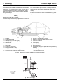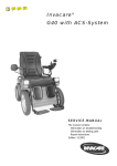
1
Water Heaters
Repair Shop Manual
Thermo Top Z
Supplementary Heater
Thermo Top E
Thermo Top C
Auxiliary Heater
Type Thermo Top E - B
Type Thermo Top Z/C - B
Fuel
Type Thermo Top E - D
Type Thermo Top Z/C - D
Diesel
04/2008
63378C_EN
List of Contents
1
Introduction
1.1
1.2
1.3
1.4
Scope and Purpose ............................................................................................................................... 101
Meaning of Warnings, Cautions, and Notes .......................................................................................... 101
Additional Documentation to be used .................................................................................................... 101
Safety Information and Regulations....................................................................................................... 101
1.4.1 Legal Provisions for Installation................................................................................................... 101
1.4.2 General Safety Notes .................................................................................................................. 102
1.5
2
Corrections and Improvements.............................................................................................................. 102
General Description
2.1
Combustion Air Fan Assembly .............................................................................................................. 202
2.1.1 Combustion Air Fan..................................................................................................................... 202
2.2
2.3
2.4
Burner Housing...................................................................................................................................... 202
Burner Insert .......................................................................................................................................... 202
Control Unit / Heat Exchanger ............................................................................................................... 203
2.4.1
2.4.2
2.4.3
2.4.4
2.5
2.6
3
Control Unit.................................................................................................................................. 203
Temperature Sensor.................................................................................................................... 203
Overheat Protection..................................................................................................................... 203
Heat Exchanger........................................................................................................................... 203
Circulation Pump (Thermo Top E and C only)....................................................................................... 203
Dosing Pump ......................................................................................................................................... 203
Functional Description
3.1
Functional Description Thermo Top Z (Supplementary Heater) ............................................................ 301
3.1.1 Switch On / Starting..................................................................................................................... 301
3.1.2 Heating Operation ....................................................................................................................... 301
3.1.3 Switch Off / Deactivation ............................................................................................................. 301
3.2
Functional Description Thermo Top E and C (Auxiliary Heater)............................................................ 302
3.2.1
3.2.2
3.2.3
3.2.4
4
Switch On .................................................................................................................................... 302
Heating Operation ....................................................................................................................... 302
Switch Off .................................................................................................................................... 302
Auxiliary Heater in Supplementary Heater Function.................................................................... 303
Technical Data
4.1
4.2
4.3
Thermo Top E........................................................................................................................................ 401
Thermo Top Z/C (Heating Flow 5.0 kW)................................................................................................ 402
Thermo Top Z/C (Heating Flow 5.2 kW)................................................................................................ 403
5
Troubleshooting
5.1
5.2
5.3
General Fault Symptoms ...................................................................................................................... 501
Error Messages during Functional Test with Diagnosis Tester Thermo Test ....................................... 502
Malfunctions.......................................................................................................................................... 503
5.3.1 Error Lockout by Malfunction of Heater ...................................................................................... 503
5.3.2 Error Lockout due to Low or High Voltage.................................................................................. 503
5.3.3 Error Lockout Reset.................................................................................................................... 503
6
Functional Checkouts
6.1
6.2
General ................................................................................................................................................. 601
Functional Tests in the Vehicle ............................................................................................................. 601
6.2.1
6.2.2
6.2.3
6.2.4
6.2.5
6.2.6
6.3
Heating Operational Test (Thermo Top E and C).......................................................................
Timer Functional Test (Thermo Top E and C) ............................................................................
Telestart T60 Functional Test (Thermo Top C) ..........................................................................
Telestart T70 Functional Test (Thermo Top C and E) ................................................................
Functional Test with Diagnosis Tester Thermo Test ..................................................................
CO2 Setting ................................................................................................................................
601
602
602
602
603
604
Repair Shop Level Testing.................................................................................................................... 604
6.3.1 Components Testing................................................................................................................... 604
7
Circuit Diagrams
7.1
8
General .................................................................................................................................................. 701
Servicing
8.1
8.2
8.3
8.4
8.5
8.6
8.7
General .................................................................................................................................................
Work on the Heater...............................................................................................................................
Work on the Vehicle..............................................................................................................................
Heater Test Run....................................................................................................................................
Servicing ...............................................................................................................................................
Visual Inspections and Installation Regulations....................................................................................
801
801
801
801
801
801
8.6.1
8.6.2
8.6.3
8.6.4
801
803
805
805
Connection to Vehicle Cooling System.......................................................................................
Connection to Vehicle Fuel System............................................................................................
Air Intake Muffler.........................................................................................................................
Exhaust Line ...............................................................................................................................
Removal and Installation....................................................................................................................... 806
8.7.1 Heater, Removal and Installation................................................................................................ 806
8.7.2 Timer, Removal and Installation ................................................................................................. 806
8.8
Initial Operation..................................................................................................................................... 806
9
Repair
9.1
General .................................................................................................................................................. 901
9.1.1 Work on Components after Disassembly .................................................................................... 901
9.2
Disassembly and Assembly................................................................................................................... 902
9.2.1
9.2.2
9.2.3
9.2.4
10
Circulation Pump, Replacement (Thermo Top E and C) ............................................................. 902
Combustion Air Fan, Replacement.............................................................................................. 903
Burner Insert with Glow Plug / Flame Sensor, Replacement ...................................................... 905
Control Unit / Heat Exchanger with Burner Housing, Replacement ............................................ 905
Packaging, Storage and Shipping
10.1 General ................................................................................................................................................ 1001
List of Figures
Thermo E and Top Z/C
List of Figures
501
502
Fault Symptoms ......................................................................................................................................... 501
Error Messages.......................................................................................................................................... 502
701
702
703
704
Control Unit Connector Pin Assignment (Thermo Top E and C) ...............................................................
Automatic Switching Circuit for Thermo Top E and Z/C, 12 V Timer and Telestart T60............................
Automatic Switching Circuit for Thermo Top E and Z/C, 12 V Timer .........................................................
Automatic Switching Circuit for Thermo Top Z, 12 V .................................................................................
701
702
703
704
801
802
803
804
805
806
807
808
809
"Inline Integration" in the Engine Water Cooling Circuit .............................................................................
Example for Heater Installation in Passenger Vehicle ...............................................................................
Fuel Supply ................................................................................................................................................
Webasto Fuel Tap......................................................................................................................................
Pipe/Hose Connection ...............................................................................................................................
Dosing Pump, Installation Position ............................................................................................................
Air Intake Muffler, Installation Position.......................................................................................................
Exhaust Pipe Outlet, Installation Position ..................................................................................................
Timer, Removal and Installation ................................................................................................................
801
802
802
803
804
804
805
805
806
901
902
Replacement of Circulation Pump (Thermo Top E and C) ........................................................................ 902
Heater Disassembly................................................................................................................................... 904
IV
Thermo Top E and Z/C
1
Introduction
1.1
Scope and Purpose
This repair shop manual is intended to support
familiarised personnel in the repair of the water heaters
Thermo Top E, Thermo Top Z and Thermo Top C of the
fuel and Diesel types.
As their appearance is identical or similar, the heaters are
marked by type on their identification plate with "Benzin"
(fuel) or "Diesel". The heaters may only be operated with
the specified type of Diesel (or with fuel oil EL) and the
appropriate type of electrical installation.
Heaters which have Diesel or fuel specified on their
identification plate must not be operated with PME
(vegetable methyl ester).
Thermo Top E and C are variants of Thermo Top Z with a
circulation pump.
1.2
Meaning of Warnings, Cautions,
and Notes
WARNINGS, CAUTIONS, and NOTES in this manual
have the following meaning:
WARNING
This heading is used to highlight that non-compliance with
instructions or procedures may cause injuries or lethal
accidents to personnel.
CAUTION
This heading is used to highlight that non-compliance with
instructions or procedures may cause damage to
equipment.
NOTE
This heading is used to highlight and draw specific
attention to information.
1.3
Additional Documentation to be
used
This workshop manual contains all information and
procedures necessary for the repair of water heaters
Thermo Top E, Thermo Top Z and Thermo Top C.
The use of additional documentation is normally not
necessary.
Operating instructions/installation instructions and the
vehicle specific installation proposal may be used as
complementary information as necessary.
1 Introduction
1.4
Safety Information and Regulations
The general safety regulations for the prevention of
accidents and the relevant operating safety instructions
have to be observed at all times.
"General Safety Regulations" beyond the scope of these
regulations are detailed in the following.
The specific safety regulations applicable to this manual
are highlighted in the individual chapters by Warnings,
Cautions, and Notes.
1.4.1 Legal Provisions for Installation
Within the scope of the StVZO (Road Licensing
Regulations of the Federal Republic of Germany) "Design
General Approvals" laid down by the Federal Office for
Motor Traffic exist for the Water Heaters Thermo Top with
the following official marks of conformity:
~ S316 for Heater Thermo Top E-B (fuel type)
~ S317 for Heater Thermo Top E-D (Diesel type)
~ S292 for Heater Thermo Top Z/C-B (fuel type)
and
~ S289 for Heater Thermo Top Z/C-D (Diesel type).
Installation of the heater is to be performed in accordance
with the installation instructions and must be checked in
case of
a) the vehicle type inspection in accordance with
§ 20 StVZO
b) the individual inspection in accordance with
§ 21 StVZO or
c) the examination in accordance with § 19 StVZO
performed by an officially authorised expert or
examiner for road traffic, a vehicle inspector or a
public servant as per section 4 of Annex VIIIb to the
StVZO.
In the event of c) the installation must be certified on the
acceptance certificate included in the copy of the “General
Operating License” giving details about
– manufacturer
– type of vehicle and
– vehicle identification number.
This validates the “Design General Approval”. The
acceptance certificate must be kept with the vehicle.
The obligation to apply for a new "Operating License"
(with expertise) after heater installation does not
exist, if the installation meets entirely the
requirements of an installation instruction, for which
a special supplement exists for the "Design General
Approval". The "Design General Approval" and the
"Operating License" documentation are to be kept
with the vehicle.
The heaters are cleared for heating the vehicle engine
and the vehicle cabin. When using the heaters in vehicles
not subject to the Road Licensing Regulations (StVZO)
(e.g. ships), the applicable partially regional regulations
1
1 Introduction
must be observed. The use of the heater in "vehicles for
the transportation of dangerous goods" (ADR) is not
permitted.
Thermo Top E and Z/C
•
the heater mode of operation – at least "on" or "off" –
must be clearly visible.
1.4.2 General Safety Notes
The examination is performed by presentation of the
manufacturer’s operating/installation instructions.
The year of first operation must be durably marked by
the installer on the heater identification label by removing
the numerals of the years not applicable.
The heater must not be installed in the passenger or driver
compartments of vehicles.
The heater may only be installed in vehicles or
independent heating systems with a minimum coolant
capacity of 4 litres.
When checking the cooling water level proceed in
accordance with the vehicle manufacturer's instructions.
The water in the heating circuit of the heater must contain
at least 10 % of a quality brand anti-freeze.
Extracting combustion air from the vehicle interior is
prohibited.
The exhaust line outlet is to point downwards or to the
side, or in case of exhaust venting below the vehicle floor,
to be located at the nearest possible location of the
vehicle's or cockpit side or rear end.
Exhaust lines must be routed so that exhaust fumes are
unlikely to penetrate into the vehicle's interior. The
function of any part of the vehicle essential for operation
must not be impaired. Accumulations of condensate in the
exhaust line must be directly drained. A drain hole may be
provided as required.
The openings of the combustion air inlet and the exhaust
outlet must not allow a ball of 16 mm in diameter to be
inserted.
Electrical lines and switching gear of the heater must be
located in the vehicle so that their proper function cannot
be impaired under normal operating conditions.
For the routing of fuel lines and the installation of
additional fuel tanks §§ 45 and 46 of the StVZO are to be
adhered to. The most important regulations are:
•
fuel lines are to be designed in such a way that they
remain unaffected by torsional stresses in the vehicle,
engine movement, and the like. They must be
protected against mechanical damage. Fuel-carrying
parts are to be protected against excessive heat and
are to be arranged so that any dripping or evaporating
fuel can neither accumulate nor be ignited by hot
components or electrical equipment.
•
the heater must not be located in rooms
accommodating persons.
2
At filling stations and fuel depots the heater must be
switched off as there is a potential danger of explosion.
Due to the danger of poisoning and suffocation the heater
must not be operated, not even with timer or under remote
radio control (Telestart), in enclosed areas such as
garages or workshops not equipped with an exhaust
venting facility.
In the vicinity of the heater a temperature of 120° C
(storage temperature) must not be exceeded under any
circumstances (e.g. during body paint work). Excessive
temperatures may cause permanent damage to the
electronics.
All fuel lines must have leak-proof connections, must
show no damage and must be checked in regular intervals
(at least to the same schedule as the vehicle itself).
Should damage or leakage be detected, it is not permitted
to continue heater operation until the damage has been
rectified by an authorized Webasto repair shop.
NOTE
Make heater inoperative by removing fuse. The fuel lines
(Mecanyl hoses) must not come into direct contact with
exhaust pipe and must be thermally insulated to prevent
fires.
Non-compliance with the installation instructions will void
the Webasto warranty. The same applies for unskilled
repairs or repairs not using original spare parts. This will
also void the general marks of conformity of the heater
and thus the vehicle’s permit of operation.
Before first operation make sure to read the heater
operating instructions.
1.5
Corrections and Improvements
Deficiencies, improvements, or proposals for correction of
this workshop manual are to be mailed to:
Webasto Thermosysteme GmbH
Abt. Technische Dokumentation
D-82131 Stockdorf
Telefon: 089/85794-542
Telefax: 089/85794-757
Thermo Top E and Z/C
2
2 General Description
General Description
The water heater Thermo Top Z (supplementary heater)
is intended to compensate for the shortage in heat
generated by engines optimised for low fuel consumption.
The water heater Thermo Top E and C (auxiliary heater)
is used to:
• heat the vehicle cabin,
• defrost the vehicle windscreens,
• preheat water-cooled vehicle engines.
The heater Thermo Top Z may be converted into an
auxiliary heater using a retrofit kit.
The heater designed to the evaporator principle operates
intermittently controlled by the temperature sensor.
In order to minimise the battery's workload the heater
switches from full-load operation to part-load operation
after reaching a water temperature of 72° C.
In this mode of operation the heater operates with
extremely low noise and particularly low power and fuel
consumption.
The heater consists of the combustion air fan assembly,
the control unit/heat exchanger, the burner insert and the
combustion chamber. The Thermo Top E and C heater
has an additional circulation pump.
Control unit/
heat exchanger
Combustion air fan assembly
Control unit/
heat exchanger
Combustion air fan assembly
Combustion chamber
Combustion chamber
Circulation pump
Thermo Top Z
Thermo Top E and C
1
2 General Description
2.1
Thermo Top E and Z/C
Combustion Air Fan Assembly
The combustion air fan assembly includes the
combustion air fan
combustion air line inlet
fuel supply inlet.
The heater Thermo Top E and Z has the circulation pump
mounted on the combustion air fan assembly.
2.1.1 Combustion Air Fan
The combustion air fan delivers the air required for
combustion from the combustion air inlet to the burner
insert.
Coolant
outlet
Coolant
inlet
Exhaust outlet
Burner Housing
2.3
Burner Insert
Inside the burner insert fuel is distributed across the
combustion pipe fuel cross section. Combustion of the
fuel/air mixture takes place within the combustion pipe to
heat the heat exchanger.
Combustion Air Fan Assembly
2.2
Burner Housing
The glow plug/flame sensor located in the burner insert
ignites the fuel/air mixture during start of the heater. After
start the glow plug / flame sensor operates in the flame
sensor function. The glow plug / flame sensor designed as
an electrical resistor is located in the burner insert
opposite the flame side.
The burner housing includes the
coolant inlet
coolant outlet
exhaust outlet.
The burner housing accommodates the burner insert and
is combined with the control unit / heat exchanger to an
assembly.
Burner Insert
2
Thermo Top E and Z/C
2.4
2 General Description
Control Unit / Heat Exchanger
The control unit / heat exchanger includes the
control unit
temperature sensor
overheat protection
heat exchanger
connector terminal.
2.4.4 Heat Exchanger
The heat exchanger transfers the heat generated by
combustion to the coolant circuit.
2.5
CAUTION
The control unit / heat exchanger and the burner housing
represent an assembly and must not be disassembled.
Circulation Pump
(Thermo Top E and C only)
The circulation pump ensures circulation of the coolant
within the vehicle and heater coolant circuit. The pump is
activated by the control unit and is in continuous
operation.
Control Unit
Connector Terminal
Circulation Pump
Heat Exchanger
2.6
2.4.1 Control Unit
The control unit is the central unit and ensures control and
monitoring of combustion operation.
Dosing Pump
The dosing pump is a combined delivery, dosing and
shut-off system for the fuel supply of the heater out of the
vehicle fuel tank.
The control unit is ventilated by means of a ventilation
hose routed from the combustion air collector
compartment of the burner.
2.4.2 Temperature Sensor
The temperature sensor senses the coolant temperature
in the heat exchanger of the heater as an electrical
resistance. This signal is routed to the control unit for
processing.
Dosing Pump DP 2 for Fuel operated Heaters
2.4.3 Overheat Protection
Overheat protection, controlled by a temperature resistor,
protects the heater against undue operating temperatures.
Overheat protection responds at a water temperature in
excess of 105° C and switches the heater off.
Dosing Pump DP 30.2 for Diesel operated Heaters
3
2 General Description
Page free for notes
4
Thermo Top E and Z/C
Thermo Top E and Z/C
3
Functional Description
3.1
Functional Description Thermo Top Z
(Supplementary Heater)
3.1.1 Switch On / Starting
Fuel
When starting the vehicle engine the heater goes in
standby. With a water circuit temperature below 60° C and
an outside temperature below 5° C (option with outside
temperature sensor) the starting sequence commences.
The glow plug and the combustion air fan are activated.
After 30 seconds the fuel dosing pump starts operation
and combustion air fan operation is suspended for
3 seconds. Subsequently the combustion air fan speed is
increased in a ramp within 57 seconds to nearly full load
operation.
After reaching full load fuel delivery within this period the
glow plug is deactivated and the combustion air fan
operation increased to full load.
During the subsequent 45 seconds as well as in normal
operation the glow plug functions as flame sensor to
monitor the flame condition.
After all these events the automatically controlled heating
operation starts. In case of a no flame condition or a
flameout, a restart is automatically initiated. If the no flame
condition persists, fuel delivery is stopped and the heaters
enters an error lockout with a run-down of the combustion
air fan.
Diesel
When starting the vehicle engine the heater goes in
standby. With a water circuit temperature below 60° C and
an outside temperature below 5° C (option with outside
temperature sensor) the starting sequence commences.
The glow plug and the combustion air fan are activated.
After 30 seconds the fuel dosing pump starts operation
and combustion air fan operation is suspended for
3 seconds. Subsequently the combustion air fan speed is
increased in two ramps within 56 seconds to nearly full
load operation. After a stabilisation phase (constant
speed) of 15 seconds the combustion air fan speed is
again increased in a ramp within 50 seconds to nearly full
load.
After reaching full load fuel delivery the glow plug is
deactivated and the combustion air fan operation
increased to full load.
During the subsequent 45 seconds as well as in normal
operation the glow plug functions as flame sensor to
monitor the flame condition.
After all these events the automatically controlled heating
operation starts. In case of a no flame condition or a
flameout, a restart is automatically initiated. If the no flame
condition persists, fuel delivery is stopped and the heater
enters an error lockout with a run-down of the combustion
air fan.
A flameout during normal combustion operation causes
an automatic restart.
3 Functional Description
3.1.2 Heating Operation
Fuel
When the temperature rises to reach 72° C the heater
switches to the energy saving part load operation. A rise
in temperature up to 76.5° C causes the heater to enter a
control idle period. This also happens when exceeding a
total heating operating time of 76 minutes.
After cool-down of the coolant to 71° C the heater
resumes part load operation. Another rise in temperature
to 76.5° C causes the heater to enter again the control idle
period. A drop in the coolant temperature during part load
operation due to an increased demand in heat will cause
the heater to switch to full load operation at 56° C.
Diesel
Heating operation for the Diesel type heater is identical in
the sequence of events. Should the coolant temperature
drop during the control idle period to but not below 71° C
within 900 seconds, a subsequent drop in the coolant
temperature below 71° C causes the heater to perform a
regular starting sequence into full load operation.
A drop in the coolant temperature during part load
operation due to an increased demand in heat will cause
the heater to switch to full load operation at 65° C.
3.1.3 Switch Off / Deactivation
When turning the engine off the heater is deactivated.
Combustion stops and run-down commences. The
combustion air fan first continues operation to cool the
heater down (run-down) to be automatically switched off
afterwards.
NOTE
The run-down time and the combustion air fan speed
depend on the heater operating condition at the time of
deactivation.
Run-down time is for:
Fuel
168 seconds when deactivated in full load operation and
157 seconds when deactivated in part load operation.
Diesel
175 seconds when deactivated in full load operation and
100 seconds when deactivated in part load operation.
Dependent on the software variant implemented in the
control unit there might be deviations from those run-down
periods.
1
3 Functional Description
3.2
Functional Description
Thermo Top E and C (Auxiliary Heater)
3.2.1 Switch On
Fuel
When operating the "instant heat" switch button the timer
display shows or when operating the switch on the
Telestart transmitter the operating indicator light on the
transmitter flashes. This puts the heater in standly.
The glow plug, the combustion air fan and the circulation
pump are activated. After 30 seconds the fuel dosing
pump starts operation and combustion air fan operation is
suspended for 3 seconds.
Subsequently the combustion air fan speed is increased
in a ramp within 57 seconds to nearly full load operation.
After reaching full load fuel delivery within this period the
glow plug is deactivated and the combustion air fan
operation increased to full load.
During the subsequent 45 seconds as well as in normal
operation the glow plug functions as flame sensor to
monitor the flame condition.
After all these events the automatically controlled heating
operation starts. In case of a no flame condition or a
flameout, a restart is automatically initiated. If the no flame
condition persists, fuel delivery is stopped and the heater
enters an error lockout with a run-down of the combustion
air fan.
Diesel
When operating the "instant heat" switch button the timer
display shows or when operating the switch on the
Telestart transmitter the operating indicator light on the
transmitter flashes. This puts the heater in standby.
The glow plug, the combustion air fan and the circulation
pump are activated. After 30 seconds the fuel dosing
pump starts operation and combustion air fan operation is
suspended for 3 seconds.
Subsequently the combustion air fan speed is increased
in two ramps within 56 seconds to nearly full load
operation. After a stabilisation phase (constant speed) of
15 seconds the combustion air fan speed is again
increased in a ramp within 50 seconds to nearly full load.
After reaching full load fuel delivery the glow plug is
deactivated and the combustion air fan operation
increased to full load.
During the subsequent 45 seconds as well as in normal
operation the glow plug functions as flame sensor to
monitor the flame condition.
After all these events the automatically controlled heating
operation starts. In case of a no flame condition or a
flameout, a restart is automatically initiated. If the no flame
condition persists, fuel delivery is stopped and the heater
enters an error lockout with a run-down of the combustion
air fan.
A flameout during normal combustion operation causes
an automatic restart.
2
Thermo Top E and Z/C
3.2.2 Heating Operation
Fuel
When the temperature rises to reach 72° C the heater
switches to the energy saving part load operation. A rise
in temperature up to 76.5° C causes the heater to enter a
control idle period. This also happens when exceeding a
total heating operating time of 76 minutes.
The circulation pump, the vehicle's own heating air fan,
and the operation indicator light remain on during control
idle.
After cool-down of the coolant to 71° C the heater
resumes part load operation. Another rise in temperature
to 76.5° C causes the heater to enter again the control idle
period. A drop in the coolant temperature during part load
operation due to an increased demand in heat will cause
the heater to switch to full load operation at 56° C.
Diesel
Heating operation for the Diesel type heater is identical in
the sequence of events. Should the coolant temperature
however not drop within 900 seconds during the control
idle period to below 71° C, a subsequent drop in the
coolant temperature below 71° C causes the heater to
perform a regular starting sequence into full load
operation.
3.2.3 Switch Off
When turning the heater off by pushing the "instant heat"
switch button
( in indicator panel extinguishes) or
when operating the switch on the Telestart (flashing
indicator on hand-held transmitter extinguishes) the
vehicle heating air fan stops.
Combustion terminates and run-down commences. The
circulation pump and the combustion air fan first continue
operation to cool the heater down (run-down) to be
automatically switched off afterwards.
NOTE
The run-down time and the combustion air fan speed
depend on the heater operating condition at the time of
deactivation.
Run-down time is for:
Fuel
168 seconds when deactivated in full load operation and
157 seconds when deactivated in part load operation.
Diesel
175 seconds when deactivated in full load operation and
100 seconds when deactivated in part load operation.
Dependent on the software variant implemented in the
control unit there might be deviations from those run-down
periods.
Thermo Top E and Z/C
3 Functional Description
3.2.4 Auxiliary Heater in Supplementary Heater
Function
3.2.4.1 Switch On
When starting the engine the heater goes in standby
(see 3.1.1).
With the temperature of the water circuit below 60° C and
the outside temperature below 5° C (option with external
temperature sensor) the starting procedure is initiated.
NOTE
When operating in the supplementary heater function
there will be no automatic trigger of the circulation pump
and the vehicle's heating air fan.
3.2.4.2 Switch Off
Turning the engine off deactivates the heater.
Combustion is terminated and run-down commences.
The combustion air fan however continues operation to
cool the heater down (run-down) to be automatically
switched off afterwards (see 3.1.3).
3
3 Functional Description
Page free for notes
4
Thermo Top E and Z/C
Thermo Top E and Z/C
4
Technical Data
4.1
Thermo Top E
4 Technical Data
Propellant for Thermo Top E (Fuel):
The proper fuel is the fuel specified by the vehicle
manufacturer.
Where no threshold values are specified technical data in
the table are understood to include standard tolerances
for heater units of ± 10 % at an ambient temperature of
+ 20° C.
All electrical components are selected for a nominal
voltage of 12 Volts.
Heater
Operation
Mark of conformity
Propellant for Thermo Top E (Diesel):
The proper Diesel fuel is the one specified by the vehicle
manufacturer. When switching to low temperature
propellants the heater must be operated for at least
15 minutes to prime the fuel pipe and pump with the new
type of fuel.
A persistent influence by additives is not known.
Thermo Top E - B
~ S316
Type
Heating flow
Full load
Part load
Fuel
Full load
Part load
Diesel
0.54 l/h
0.34 l/h
Diesel/PME*
0.47 l/h
0.30 l/h
12 V
Operating voltage range
Permissible ambient temperature:
Heater:
– operation
– storage
Dosing pump:
– operation
~ S317
4.0 kW
2.5 kW
Nominal voltage
Nominal power consumption without
circulation pump (without vehicle air fan)
Thermo Top E - D
Water heater with evaporator burner
Fuel
Fuel consumption
Thermo Top E - D
10.5 ... 15 V
Full load
Part load
22 W
18 W
–40° C ... + 60° C
–40° C ... +120° C
–40° C ... + 20° C
Permissible operating overpressure
(heat carrier)
–20° C ... + 60° C
–40° C ... +120° C
–20° C*... + 20° C
0.4 ... 2.5 bar
Heat exchanger capacity
0.15 l
Minimum coolout circuit capacity
3.00 l
Minimum volume flow for the heater
250 l/h
CO2 in exhaust (permissible functional range)
Dimensions of heater
8 ... 12 Vol.-%
length
width
height
214 mm
106 mm
168 mm
Weight
2.9 kg
Circulation pump
4847
Volume flow against 0.1 bar
Nominal voltage
Operating voltage range
Nominal power consumption
Dimensions of circulation pump
Weight
900 l/h
12 V
10.5 ... 15 V
14 W
length
width
height
95 mm
61 mm
61 mm
0.3 kg
*) Operation only permitted with mixture Diesel/PME with PME quantity < 50 %.
1
4 Technical Data
4.2
Thermo Top E and Z/C
Thermo Top Z/C
(Heating Flow 5.0 kW)
Propellant for Thermo Top Z/C (Fuel):
The proper fuel is the fuel specified by the vehicle
manufacturer
Where no threshold values are specified technical data in
the table are understood to include standard tolerances
for heater units of ± 10 % at an ambient temperature of
+ 20° C.
All electrical components are selected for a nominal
voltage of 12 Volts.
Heater
Operation
Mark of conformity
Propellant for Thermo Top Z/C (Diesel):
The proper Diesel fuel is the one specified by the vehicle
manufacturer. When switching to low temperature
propellants the heater must be operated for at least
15 minutes to prime the fuel pipe and pump with the new
type of fuel.
A persistent influence by additives is not known.
Thermo Top
Z/C - B
~ S292
Type
Heating flow
~ S289
Full load
Part load
5.0 kW
2.5 kW
Fuel
Full load
Part load
Diesel
0.67 l/h
0.34 l/h
12 V
Operating voltage range
10.5 ... 15 V
Full load
Part load
Permissible ambient temperature:
Heater:
– operation
– storage
Dosing pump:
– operation
Permissible operating overpressure
(heat carrier)
26 W
18 W
–40° C ... + 60° C
–40° C ... +120° C
–40° C ... + 20° C
–20° C ... + 60° C
–40° C ... +120° C
–20° C*... + 20° C
0.4 ... 2.5 bar
Heat exchanger capacity
0.15 l
Minimum coolout circuit capacity
4.00 l
Minimum volume flow for the heater
250 l/h
CO2 in exhaust (permissible functional range)
Dimensions of heater
8 ... 12 Vol.-%
length
width
height
214 mm
106 mm
168 mm
Weight
2.9 kg
Circulation pump
4847
Volume flow against 0.1 bar
900 l/h
Nominal voltage
Operating voltage range
Nominal power consumption
Dimensions of circulation pump
Weight
*) If viscosity of PME permits due to its natural condition.
2
Diesel/PME*
0.59 l/h
0.30 l/h
Nominal voltage
Nominal power consumption without
circulation pump (without vehicle air fan)
Thermo Top
Z/C - D
Water heater with evaporator burner
Fuel
Fuel consumption
Thermo Top
Z/C - D
12 V
10.5 ... 15 V
14 W
length
width
height
95 mm
61 mm
61 mm
0.3 kg
Thermo Top E and Z/C
4.3
4 Technical Data
Thermo Top Z/C
(Heating Flow 5.2 kW)
Propellant for Thermo Top Z/C (Fuel):
The proper fuel is the fuel specified by the vehicle
manufacturer
Where no threshold values are specified technical data in
the table are understood to include standard tolerances
for heater units of ± 10 % at an ambient temperature of
+ 20° C.
All electrical components are selected for a nominal
voltage of 12 Volts.
Heater
Operation
Mark of conformity
Propellant for Thermo Top Z/C (Diesel):
The proper Diesel fuel is the one specified by the vehicle
manufacturer. When switching to low temperature
propellants the heater must be operated for at least
15 minutes to prime the fuel pipe and pump with the new
type of fuel.
A persistent influence by additives is not known.
Thermo Top
Z/C - B
~ S292
Type
Heating flow
Full load
Part load
~ S289
5.2 kW
2.5 kW
Fuel
Full load
Part load
Nominal voltage
Diesel
0.70 l/h
0.34 l/h
Diesel/PME*
0.61 l/h
0.30 l/h
12 V
Operating voltage range
Nominal power consumption without
circulation pump (without vehicle air fan)
Thermo Top
Z/C - D
Water heater with evaporator burner
Fuel
Fuel consumption
Thermo Top
Z/C - D
10.5 ... 15 V
Full load
Part load
Permissible ambient temperature:
Heater:
– operation
– storage
Dosing pump:
– operation
Permissible operating overpressure
(heat carrier)
28 W
18 W
–40° C ... + 60° C
–40° C ... +120° C
–40° C ... + 20° C
–20° C ... + 60° C
–40° C ... +120° C
–20° C*... + 20° C
0.4 ... 2.5 bar
Heat exchanger capacity
0.15 l
Minimum coolout circuit capacity
4.00 l
Minimum volume flow for the heater
250 l/h
CO2 in exhaust (permissible functional range)
Dimensions of heater
8 ... 12 Vol.-%
length
width
height
214 mm
106 mm
168 mm
Weight
2.9 kg
Circulation pump
4847
Volume flow against 0.1 bar
Nominal voltage
Operating voltage range
Nominal power consumption
Dimensions of circulation pump
Weight
900 l/h
12 V
10.5 ... 15 V
14 W
length
width
height
95 mm
61 mm
61 mm
0.3 kg
*) If viscosity of PME permits due to its natural condition.
3
4 Technical Data
Page free for notes
4
Thermo Top E and Z/C
Thermo Top E and Z/C
5
Troubleshooting
5.1
General Fault Symptoms
5 Troubleshooting
The following table (Fig. 501) lists possible fault
symptoms of general nature for heaters in installed
condition.
CAUTION
Troubleshooting requires profound knowledge about
components and their theory of operation and may only be
performed by trained personnel.
In case of doubt functional interrelations may be derived
from Sections 2 and 3.
CAUTION
Troubleshooting is normally limited to the isolation of
defective components and provides information on
defective wiring and connections.
The following possible causes for trouble have not been
taken into consideration and must always be excluded as
a possible cause for malfunctions:
corrosion on connectors
loose contacts on connectors
wrong crimping on connectors
corrosion on wiring and fuses
corrosion on battery terminals
After any fault correction a functional checkout in the
vehicle has to be performed (see 6.2).
Symptom
Remedy
Smell of fuel
Check heater system integration in vehicle's fuel system.
Check fuel lines for leakage, kinks or obstructions. If o.k.
there is a heater internal leak. Remove heater and
perform troubleshooting on repair shop level.
Heater does not achieve full load operation
Remove heater and perform troubleshooting on repair
shop level.
Continuous white smoke during combustion operation
Remove heater and perform troubleshooting on repair
shop level.
Heater cannot be switched off
Perform functional test of Timer (see 6.2.2) or of
Telestart device (see 6.2.3). Replace or repair defective
component.
Loss of coolant (dripping);
heater develops smoke during combustion operation;
smell of exhaust fumes extremely sweet
Inspect coolant hoses for leakage, kinks, loose hose
clamps, etc.
If o.k. there is a heater internal leak.
Remove heater and perform troubleshooting on repair
shop level.
Loss of fuel (dripping)
Check heater system integration in vehicle's fuel system.
Check fuel line connections for leakage. If o.k. there is a
heater internal leak.
Remove heater and perform troubleshooting on repair
shop level.
Fig. 501 Fault Symptoms
1
5 Troubleshooting
5.2
Thermo Top E and Z/C
Error Messages during
Functional Test with Diagnosis Tester
Thermo Test
NOTE
The following table (Fig. 502) lists possible error
messages during the functional test with the diagnosis
tester and their probable cause.
Error Message
Probable Cause
Control unit defective
• Faulty electronics
• EOL programming error
Flame-out 1
Flame-out during operation and no flame-up after a new attempt to start
•
•
•
•
•
•
•
•
•
•
Flame-out 2
Wrong integration in fuel system (e.g. fuel supply confused with return)
Fuel tapping dependent on fuel level
Pressure in fuel system too low
Check valve in fuel system
Leak in fuel line connections
Degassing fuel lines (routed in environment too hot)
Installation orientation of dosing pump
Combustion air intake not as specified
Exhaust system not as specified
Burner defective
Several flame-outs during operation
•
•
•
•
•
•
•
•
•
•
Wrong integration in fuel system (e.g. fuel supply confused with return)
Fuel tapping dependent on fuel level
Pressure in fuel system too low
Check valve in fuel system
Leak in fuel line connections
Degassing fuel lines (routed in environment too hot)
Installation orientation of dosing pump
Combustion air intake not as specified
Exhaust system not as specified
Burner defective
Voltage too high
• Vehicle battery charger probably defective
Voltage too low
• Battery discharged or defective
• High transition resistance in the power supply lines (plus and minus)
Flame before combustion
operation (not applicable for
Thermo Top Z)
• Glow plug / flame sensor defective
Overheating
• Coolant level too low
• Heater has not been bled
• No circulation
Dosing pump short circuit
• Ground short in power supply line to dosing pump
Dosing pump open circuit
• Open line to dosing pump
• Short circuit to plus of power supply
Burner motor short circuit
Thermo Top Z:
• Switched line short circuit to plus of power supply
• Overload or short circuit of burner motor
Thermo Top E und C:
• Ground short in power supply line to burner motor
Burner motor open circuit
• Open line to burner motor
• Short circuit to plus of power supply
Fig. 502 Error Messages (Sheet 1 of 2)
2
Thermo Top E and Z/C
Glow plug short circuit
5 Troubleshooting
Thermo Top Z:
• Switched line short circuit to plus of power supply
• Overload or short circuit of glow plug
Thermo Top E und C:
• Ground short in power supply line to glow plug
Glow plug open circuit
Open line to glow plug / flame sensor
• Short circuit to plus of power supply
• Rise in coolant temperature within 9 min after start is < 3 K (Thermo Top C only)
Water pump short circuit
Thermo Top Z:
• Switched line short circuit to plus of power supply
• Overload or short circuit of circulation pump
Thermo Top E und C:
• Ground short in power supply line to circulation pump
• Overload
Water pump open circuit
• Open line to circulation pump
• Short circuit to plus of power supply
Fan short circuit
• Line to fan relay shorted against ground
• Overload of output to fan trigger ( I > 500 mA)
Fig. 502 Error Messages (Sheet 2 of 2)
5.3
Malfunctions
5.3.1 Error Lockout by Malfunction of Heater
In case of a "no flame-up" condition fuel is delivered for a
maximum of 180 seconds.
In the event of overheating (temperature limiter responds)
fuel delivery is stopped immediately.
5.3.3 Error Lockout Reset
NOTE
Before attempting an error lockout reset check fuse F1 in
Webasto flat fuse holder. A 15 A fuse must be replaced
with a 20 A fuse.
If the heater nevertheless fails to switch on, reset error
lockout according to 5.3.3.4.
F1
In all cases of malfunction (except for a defect on the
combustion air fan) there will be an error lockout with a
subsequent run-down. Dependent on the software variant
implemented there might be deviations from the run-down
times specified.
NOTE
An error lockout due to overheating does not display an
indication.
5.3.2 Error Lockout due to Low or High Voltage
A low voltage level of 9.8 ± 0.3 V (measured at the wiring
harness input) over a period of 20 seconds will cause an
error lockout with a run-down of 120 seconds.
A high voltage level of 15.5 ± 0.5 V (measured at the
heater) over a period of more than 6 seconds will also
cause an error lockout with a run-down of 120 seconds.
5.3.3.1 Error Lockout Reset Thermo Top E and C with
"Timer"
Eliminate cause of trouble.
Switch off heater using the instant heat switch on the timer
and switch on again. If heater fails to switch on, perform
error lockout reset according to 5.3.3.4.
An error lockout due to overheating does not have an
indication.
The fuse is not blown in case of overheating.
The error lockout may be cleared by disconnection of the
power supply of the control unit.
Perform error lockout reset according to 5.3.3.4.
3
5 Troubleshooting
Thermo Top E and Z/C
5.3.3.2 Error Lockout Reset Thermo Top E and C with
"Telestart"
Eliminate cause of trouble.
Switch off heater using the instant heat switch on the timer
or the Telestart hand transmitter and switch on again.
If heater fails to switch on, perform error lockout reset
according to 5.3.3.4.
An error lockout due to overheating does not have an
indication.
The fuse is not blown in case of overheating.
The error lockout may be cleared by disconnection of the
power supply of the control unit.
Perform error lockout reset according to 5.3.3.4.
5.3.3.3 Error Lockout Reset Thermo Top Z
In case of a malfunction the control unit enters an error
lockout.
The error lockout may only be cleared by disconnection of
the power supply of the control unit (e.g. by removing fuse
F1 (20 A) for at least 30 seconds).
NOTE
The fuse must be removed within 30 seconds
– after starting the engine
– after application of 12 Volts to connector X14,
contact 3
If the supplementary heater nevertheless fails to start,
perform error lockout reset according to 5.3.3.4.
5.3.3.4 Error Lockout Reset after Overheating or after
Three Error Lockouts
ON
B
Z G108
T 48
0D T
FW
wait for
approx.
or
3 sec.
25
2
A 01
A
A
Power supply
disconnect by
removal of 20 A fuse
(yellow) in heater
wiring harness
4
ON
SE
T
3 sec.
25
2
A 01
A
A
Re-installation of
fuse
wait for
approx.
wait for
approx.
3 sec.
25
2
A 01
A
A
Momentarily press ON switch left on
transmitter or press
button on timer
Power supply
disconnect by
removal of 20 A fuse
(yellow) in heater
wiring harness
25
2
A 01
A
A
Re-installation of
fuse.
This switches the
heater on.
Thermo Top E and Z/C
6
Functional Checkouts
6.1
General
This section describes the tests on the heater and its
components in installed and removed condition as well as
the test of the Timer and the Telestart T60/T70 to prove
serviceability.
WARNING
The heater must not be operated in enclosed areas like
garages or workshops not provided with exhaust
ventilation facilities.
6.2
6 Functional Checkouts
NOTE
Heating efficiency depends on several factors: for
assessment use outside temperature, type of vehicle,
engine temperature or type of heater integration in the
vehicle's cooling system, the quantity of the coolant to be
heated and the time passed since heater start.
NOTE
Take the time of the following functions with a stop watch
or any other suitable means.
6. Switch heater off using Timer or Telestart.
•
Switch off causes a run-down of approx.
110 seconds out of part load operatimon or of
175 seconds out of full load. Verification by
stoppage of exhaust emissions and audible
continuation of circulation pump operation.
•
After run-down the heater will be completely
deactivated (with ignition off).
Functional Tests in the Vehicle
6.2.1 Heating Operational Test
(Thermo Top E and C)
1. Ensure that fan switch is set to the lowest stage or the
stage recommended in the operating instructions.
2. Ensure that the air intake is free from foreign matter
(snow, leaves etc.) and that the pollen or dust filters
(if applicable) are unobstructed.
3. Ensure that that the vehicle coolant circuit and fuel
system have been thoroughly bled in accordance with
manufacturer's instructions.
NOTE
Take the time of the following functions with a stop
watch or any other suitable means. The exact times for
the heaters, Diesel and fuel version, are described in
Section 3.
4. Switch heater on using Timer or Telestart.
•
Activation of heater causes circulation pump and
combustion air fan to operate. Operating noise is
audible. Vehicle heating air fan operates after
coolant has reached a temperature of 30° C.
•
After approx. 130 seconds the heater starts to
operate which can be verified by exhaust
emissions from the exhaust muffler or exhaust
pipe.
5. Allow heater to continue operation. Check heating
efficiency at air exit of vehicle heating air fan.
601
6 Functional Checkouts
Thermo Top E and Z/C
6.2.2 Timer Functional Test
(Thermo Top E and C)
6.2.2.2 Switch On Signal Test
6.2.2.1 Voltage Check
1. Remove cover using a small screw driver.
1. Operate "ON"
button and check voltage between
"–" and "OUT". Voltage is approx. 7 V with the timer
connected to the control unit or 12 V with the output
not connected.
2. Operate "ON" button again and check voltage
between "–" and "OUT". Voltage is 0 V.
2. Loosen screw.
3. Disconnect plug from clock.
4. Measure voltage between "+" and "-" (see figure).
Voltage indicated is according to voltage of vehicle
battery, approx. 12 V.
NOTE
In case no voltage is indicated check or replace fuse
F2 and/or timer wiring.
6.2.3 Telestart T60 Functional Test
(Thermo Top C)
6.2.3.1 Transmitter Check
1. Operate switch on transmitter. Ensure operating
indicator light (green or red LED) flashes. If LED is not
flashing, batteries are too cold or too weak.
2. Using switch on transmitter switch Telestart off.
Connection to contact
+15 remains open
6.2.4 Telestart T70 Functional Test
(Thermo Top C and E)
black
brown
red
6.2.4.1 Batteries Check
1. Operate ON or OFF switch.
Batteries
LED
serviceable
illuminates
after 1 second
for approx.
0.5 seconds
weak
flashes in
orange after
1 second for
3 seconds
SE
T
Actions
–
–
OUT +15
+
602
–
descharged
illuminates in
orange after
1 second for
5 seconds
–
–
warm up
batteries
to above 0° C
replace
batteries as
soon as
possible
warm up
batteries
to above 0° C
replace
batteries
Thermo Top E and Z/C
6 Functional Checkouts
6.2.5 Functional Test with Diagnosis Tester
Thermo Test
•
•
3. Connect red battery terminal clamp to battery plus and
black battery terminal clamp to battery minus of
vehicle.
NOTE
For operation of diagnosis tester refer to operating
instructions.
If error messages are displayed during functional
testing, perform troubleshooting according to
Section 5.
NOTE
After connection of diagnosis tester the following text is
indicated alternately:
Diagnostic Adapter
SW-Version X.XX
CAUTION
When connecting diagnosis tester the heater must be in
switched off condition.
1. Connect screw coupling of adapter wiring harness to
diagnosis tester.
Webasto
Thermosysteme
2. Connect plug (yellow wire) to diagnosis connector in
vehicle (connector with yellow wire).
By pressing any key the equipment select menu is called
up.
Working Step
Result
Indication
Press any key
Equipment selection
By pressing left key select heater and
language
•
•
•
•
Acknowledge Thermo Top E or Z/C selection
by pressing "OK" key
Main menu
By pressing left key select desired function
•
•
•
•
•
•
Thermo Top
Thermo Top E
Thermo Top Z/C
Language
Read error
Delete error
Components test
Automatic test
CO2 setting
Equipment selection
Acknowledge selected function with "OK" key
Dependent on selected function
Selection "Read error"
Error indication:
• maximum of 3 errors or no error
• return
NOTE
Heater
Record error!
Selection "Delete error"
• Error deleted
• return
Selection "Components test"
•
•
•
•
•
•
Selection "Automatic test"
• Indication of component triggered
or
• Indication of an error
Dosing pump on
Burner motor on
Glow plug / flame sensor on
Circulation pump on
Fan relay on
Cancel
Dosing pump cycles
Burner motor runs
Glow plug / flame sensor on
Circulation pump runs
Fan runs
Components are triggered as
indicated
4. Select main menu "Equipment selection" and
disconnect diagnosis tester from battery and from
diagnosis connector.
603
6 Functional Checkouts
Thermo Top E and Z/C
6.2.6 CO2 Setting
NOTE
The CO2 setting is performed with the diagnosis tester
Thermo Test. For operation of diagnosis tester refer to
operating instructions.
CAUTION
For starting heater diagnostic line must be disconnected.
Connection of diagnosis tester with heater on and
operating at full load (approx. 5 min after switch on).
Change of CO2 value in increments by pressing OK key.
For settings refer to the following table:
Nominal contents of CO2 in exhaust at full load operation [Vol.-%]
Geographic altitude
above sea level [m]
Air temperature [°C]
–20
0
20
Fuel
Diesel
Fuel
Diesel
Fuel
Diesel
10.2
11.3
10.4
11.5
10.6
11.7
1000
9.6
10.6
9.7
10.8
9.9
11.0
500
9.0
9.9
9.1
10.1
9.3
10.3
250
8.7
9.6
8.8
9.8
9.0
10.0
0
8.4
9.3
8.6
9.5
8.8
9.7
1500
1. Switch on heater and allow to operate for approx.
5 min.
2. Connect screw coupling of adapter wiring harness to
diagnosis tester.
3. Connect plug (yellow wire) to diagnosis connector in
vehicle (connector with yellow wire).
4. Connect red battery terminal clamp to battery plus and
black battery terminal clamp to battery minus of
vehicle.
9. Select submenu "Decrease CO2" or "Increase CO2".
By pressing OK key repeatedly CO2 value changes in
increments. The cursor remains positioned on the
selected function.
NOTE
By selection of "Initial value" and pressing of the OK key,
the CO2 value stored automatically during start of the CO2
setting may be restored.
By selection of "Store/return" and pressing of the OK key,
the last setting becomes the default and the main menu is
called up.
5. Switch on exhaust meter.
NOTE
After connection of diagnosis tester the following text is
indicated alternately:
10. Select main menu item "Equipment selection" and
disconnect diagnosis tester from battery and from
diagnosis connection.
11. Switch off heater.
Diagnostic Adapter
SW-Version X.XX
6.3
Repair Shop Level Testing
6.3.1 Components Testing
Webasto
Thermosysteme
By pressing any key the equipment select menu is
called up.
6. Press any key.
7. Select heater.
8. In main menu select “CO2 setting”.
604
6.3.1.1 Glow Plug / Flame Sensor Resistance Check
When testing the glow plug / flame sensor with a digital
multimeter, the following readings should be obtained:
Resistance at 24 ± 6 °C:
Test current:
0.245 ... 0.325 Ω
< 5 mA
Thermo Top E and Z/C
7
Circuit Diagrams
7.1
General
7 Circuit Diagrams
The connector pin assignment of control unit
Thermo Top E and Z/C is shown in Fig. 701.
The circuit diagrams (Fig. 702 and 703) show the
electrical circuit of the heater in combination with Timer
and Telestart T60.
The circuit diagram (Fig. 704) shows the electrical circuit
of Thermo Top Z.
2
FG
3
2
1
UP
2
BL
GS/FW
1
2
4
5
6
2
1
X5
12V+
1
2
DP
X1
1
X4
X3
1
2
3
X2
Clock Diagnosis 1
1
outside air temperature
2
summer/winter switch
3
not used
BL
DP
FG
GS/FW
UP
combustion air fan
dosing pump
vehicle air fan
glow plug / flame sensor
circulation pump
Fig. 701 Control Unit Connector Pin Assignment (Thermo Top E and C)
1
7 Circuit Diagrams
Thermo Top E and Z/C
ϑ
ϑ
4
Item
A1
A2
A3
A4
B2
E
F1
F2
F3
H1
K3
M1
M2
M3
P
S1
S2
S5
X1
X2
X3
X4
X5
X6
X8
X9
Y1
Nomenclature
Heater
Control unit
Connector box
Telestart receiver
Temperature sensor
Glow plug / flame sensor
Fuse 15 A
Fuse 1 A
Fuse 25 A
LED (in item P)
Relay (in item A3)
Motor
Motor
Motor
Timer, digital
Switch for vehicle air fan
Switch for vehicle air fan
Switch
Connection, 6-pole
Connection, 2-pole
Connection, 2-pole
Connection, 2-pole
Connection, 2-pole
Connection, 2-pole
Connection, 2-pole
Connection, 4-pole
Dosing pump
Remark
Thermo Top E or Z/C
Wire Gauges
T60
< 7.5 m
7.5 - 15 m
0,5 mm2
0,75 mm2
1,5 mm2
0,75 mm2
1,5 mm2
2,5 mm2
4,0 mm2
6,0 mm2
2,5 mm2
4,0 mm2
Flat fuse SAE J 1284
Flat fuse SAE J 1284
Flat fuse SAE J 1284
operating indicator light
vehicle air fan
combustion air fan
circulation pump
vehicle air fan
for timer operation
depending on vehicle S1 or S2
depending on vehicle S1 or S2
summer/winter switch
water repellant
water repellant
water repellant
water repellant
water repellant
HF, coaxial
Wire Colours
blue
brown
yellow
green
grey
orange
red
black
violet
white
bl
br
ge
gn
gr
or
rt
sw
vi
ws
Legend for circuit diagrams
1
Diagnosis
2
Outside air temperature
3
Vehicle heating air fan fuse
provided in vehicle
4
Option
Fig. 702 Automatic Switching Circuit for Thermo Top E and Z/C, 12 V Timer and Telestart T60
2
Thermo Top E and Z/C
7 Circuit Diagrams
X9
(75) 15
30
61
rt
ϑ
2
1
ge
sw
3
A3
F1
rt
F2
rt
2
X1
+
3
A2
1
sw
rt
OUT
+15
rt
X6
X5
X4
5
P
-
I max. = 0,5 A
gn/ws
86
K3
87
85
4
87a
1
X3
2
1
2
1 2
1
2
X2
1
2
B
H1
A
X9
C
F3
6
30
br
br
br
1
sw
1
2
3
X1
4
5
6
bl
2
X2
Lüften
Heizen
M3
Y1
M
E
2
1
X3
X4
2
1
2
X5
M
M1
M
ϑ
B2
M2
4
S2
br
br
1
S1
br
A1
br
S5
31
Item
A1
A2
A3
B2
E
F1
F2
F3
H1
K3
M1
M2
M3
P
S1
S2
S5
X1
X2
X3
X4
X5
X6
X9
Y1
Nomenclature
Heater
Control unit
Connector box
Temperature sensor
Glow plug / flame sensor
Fuse 20 A
Fuse 1 A
Fuse 25 A
LED (in item P)
Relay (in item A3)
Motor
Motor
Motor
Timer, digital
Switch for vehicle air fan
Switch for vehicle air fan
Switch
Connection, 6-pole
Connection, 2-pole
Connection, 2-pole
Connection, 2-pole
Connection, 2-pole
Connection, 2-pole
Connection, 4-pole
Dosing pump
Remark
Thermo Top E or Z/C
Flat fuse SAE J 1284
Flat fuse SAE J 1284
Flat fuse SAE J 1284
operating indicator light
vehicle air fan
combustion air fan
circulation pump
vehicle air fan
for timer operation
depending on vehicle S1 or S2
depending on vehicle S1 or S2
summer/winter switch
water repellant
water repellant
water repellant
water repellant
water repellant
Wire Gauges
< 7.5 m
7.5 - 15 m
0,5 mm2
0,75 mm2
1,5 mm2
0,75 mm2
1,5 mm2
2,5 mm2
4,0 mm2
6,0 mm2
2,5 mm2
4,0 mm2
Wire Colours
blue
brown
yellow
green
grey
orange
red
black
violet
white
bl
br
ge
gn
gr
or
rt
sw
vi
ws
Legend for circuit diagrams
1
Diagnosis
2
Outside air temperature
3
Vehicle heating air fan fuse
provided in vehicle
4
Option
Fig. 703 Automatic Switching Circuit for Thermo Top E and Z/C, 12 V Timer
3
7 Circuit Diagrams
Thermo Top E and Z/C
1
ϑ
ϑ
2
ϑ
Item
A1
A2
B2
E
F1
M1
X13
X14
X15
X16
X17
X18
X19
Y1
Nomenclature
Heater
Control unit
Temperature sensor
Glow plug / flame sensor
Fuse 20 A
Motor
Connection 2-pole
Connection 6-pole
Connection 2-pole
Connection 2-pole
Connection 2-pole
Connection 2-pole
Connection 2-pole
Dosing pump
Remark
Thermo Top Z
Wire Gauges
Flat fuse SAE J 1284
combustion air fan
water repellant
water repellant
water repellant
water repellant
water repellant
water repellant
< 7.5 m
7.5 - 15 m
0,5 mm2
0,75 mm2
1,5 mm2
0,75 mm2
1,5 mm2
2,5 mm2
4,0 mm2
6,0 mm2
2,5 mm2
4,0 mm2
Wire Colours
bl
br
ge
gn
gr
or
rt
sw
vi
ws
blue
brown
yellow
green
grey
orange
red
black
violet
white
Legend for circuit diagrams
Fig. 704 Automatic Switching Circuit for Thermo Top Z, 12 V
4
1
Diagnosis
2
Outside air temperature
Thermo Top E and Z/C
8
Servicing
8.1
General
This section describes the servicing procedures allowed
on the heater when installed.
8 Servicing
•
inspect fuel lines and fuel filter for leakage.
•
inspect coolant circuit and circulation pump
(Thermo Top E and C only) for leakage.
•
inspect hoses for cracks.
•
replace fuel filter, if installed.
WARNING
There is a potential danger of skin burns as the heater and
its components may be very hot.
8.6
8.2
8.6.1 Connection to Vehicle Cooling System
Work on the Heater
For any type of work on the heater the main power supply
cable is to be disconnected from the vehicle battery. As
long as the heater is in operation or in run-down the
battery main power supply must not be disconnected to
prevent the heater from overheating by response of the
overheat protection. When performing long time repairs
on the heater its removal is compulsory. After repairs on
the heating circuit it must be replenished with a mixture of
coolant and water to manufacturer's instructions followed
by careful bleeding of the circuit. Repairs requiring a
change of location the relevant installation instructions
and the vehicle specific heater installation proposal have
to be observed.
8.3
Visual Inspections and Installation
Regulations
The installation location of the heater should be as low as
possible to ensure self-venting of the heater and circulation
pump. This applies in particular to the circulation pump
(Thermo Top E and C only), which is not self-sucking.
The circulation pump may be installed in the location
provided on the heater or remote from the heater
integrated in the coolant circuit. The correct direction of
flow through the heater must be observed (coolant outlet
on top, coolant inlet on bottom), otherwise malfunctions
may result.
The heater is to be connected to the vehicle cooling
system according to Fig. 801 or 802. The amount of
coolant used in the circuit must be at least 4 litres.
Work on the Vehicle
CAUTION
In the vicinity of the heater a temperature of 120° C must
under no circumstances be exceeded (e.g. during paint
work on the vehicle).
The heater integration into the cooling circuit must be
upstream of the vehicle's own heat exchanger.
4
1
3
*
8.4
Heater Test Run
The heater must not be operated, not even with the timer,
in enclosed areas like garages or workshops not provided
with exhaust ventilation facilities.
8.5
6
5
WEBASTO
Engine
Motor
Normal heating water circuit
normaler Heizwasserkreislauf
Heating water
circuit when operating
Heizwasserkreislauf
bei Betrieb
with Webasto
auxiliary heater
der Webasto
Standheizung
2
1
2
3
4
Engine
with
pump
5 5 Heater
1 Motor
mit water
Wasserpumpe
Heizgerät
Radiator
6 6 Circulation
pump
2 Kühler
Umwälzpumpe
(Option)
3 Kühlerthermostat
7 (option)
WT mit Gebläse
Radiator
thermostat
4 Ausgleichsbehälter
Compensation
vessel
7 Heat exchanger with fan
7
Servicing
To ensure functional reliability of the heater the following
servicing must be performed in regular intervals:
•
clean air heater exterior (prevent the ingress of water).
•
examine electrical connections for corrosion of
contacts and for security.
•
inspect combustion air and exhaust ducting for
damage and obstructions.
Fig. 801
"Inline Integration" in the Engine Water Cooling Circuit
1
8 Servicing
Thermo Top E and Z/C
Prior to the heater's first operation or after renewal of the
coolant the cooling system must be carefully bled. The
heater and the lines must be installed to ensure static
venting.
The coolant hoses supplied by Webasto must be installed,
other hoses must meet at least the DIN 73411
requirement. The hoses are to be routed upwards as far
as possible and without kinks to ensure proper venting.
Hose connections must be protected against slippage
using hose clamps.
Insufficient venting may cause overheating during heater
operation.
NOTE
The installation of the hose clamps of the heater must be
between the bead and the heater.
The hose clamps must be torque tightened to 2.0 + 0.5 Nm.
1
2
3
4
5
6
7
8
9
10
11
12
13
14
15
16
17
18
19
Air fan of vehicle heating system
Switch for air fan of vehicle heating system
Fuse box in vehicle
Timer
Fuel tapping
Air intake muffler
Exhaust muffler
Circulation pump (only applicable for supplementary
heating)*
20 Fuel dosing pump
* part of modification kit
Radiator
Coolant thermostat
Water pump (of vehicle engine)
Vehicle engine with standard outfit
Water heater
Battery
Fuse holder
Control unit (in heater)
Relay (for vehicle air fan)
Control valve of vehicle heating system
Heat exchanger of vehicle heating system
Fig. 802 Example for Heater Installation in Passenger Vehicle
HG
max. 3 m
l2
i ø 2 mm
i ø 2 mm
H
HG
l1
l1 + I2 ≤ 7 m
l1 ≤ 1.2 m
l2 ≤ 5.8 m
l2
i ø 2 mm
i ø 2 mm
S
l1
Fig. 803 Fuel Supply
2
Thermo Top E and Z/C
8 Servicing
8.6.2 Connection to Vehicle Fuel System
In vehicles with carburettor or fuel injection including a
return line the heater fuel system integration must be
according to Fig. 802.
Carburettor engines without return line must have the
heater integrated in the fuel system's fuel supply line
between fuel tank and vehicle fuel pump.
NOTE
A fuel supply line can normally be identified by the
installation of a fuel filter. If the degassing vessel is
included in the vehicle fuel system installation, the fuel tap
must be located upstream of the degassing vessel.
The following table lists the pressures permitted at the fuel
tapping location.
Permitted fuel feed
height (H) m
at max. permissible
overpressure (bar) in fuel line
0.00
–0.20
1.00
–0.11
Permitted suction
height S (m)
at max. permissible negative
pressure (bar) in fuel tank
0.00
– 0.10
0.50
– 0.06
1.00
– 0.02
Fuel tappings from the supply or return line may only use
the special Webasto fuel tap.
The fuel tap is to be mounted so that air or gas bubbles
may escape towards the fuel tank.
Air or gas bubbles may build up in the vehicle fuel line
in case the carburettor or the fuel pump is leaking or if
ambient temperatures exceed the fuel evaporation
temperature.
The fuel tap should not be located near the engine, as gas
bubbles may build up due to the heat radiated by the
engine resulting in malfunctions of combustion operation.
When installing the heater in vehicles with fuel injection
system, the fuel pump location, internal or external of the
fuel tank, must be investigated.
With a fuel pump located inside the fuel tank, fuel may be
tapped only from the return line, ensuring that the return
line is routed almost all the way down to the fuel tank floor.
Otherwise the return line may be lengthened.
NOTE
If the fuel return line is provided with a check valve, a
bypass must be provided.
With a fuel pump located outside of the fuel tank the fuel
tap may be located between tank and fuel pump.
8.6.2.1 Fuel Lines
Fuel lines may only be steel, copper, or plastic lines made
of unhardened, light and temperature stabilised PA 11 or
PA 12 (e.g. Mecanyl RWTL) according to DIN 73378.
As in most cases a permanently rising fuel line routing
cannot be ensured, the inner diameter must not exceed a
certain value. Starting from an inside diameter of 4 mm,
air or gas bubbles accumulate resulting in malfunctions
should the lines be descending or having sags. The
diameters specified in Fig. 803 ensure no disturbing
formation of bubbles.
A descending line routing from the dosing pump to the
heater should be avoided.
Loose fuel lines must be secured in order to avoid
sagging. The installation must ensure protection against
stone impacts and undue temperatures (exhaust line).
NOTE
Hose clamps must be torque tightened to 1.0 + 0.4 Nm.
Fig. 804 Webasto Fuel Tap
3
8 Servicing
Thermo Top E and Z/C
correct
hose clamp
Preferred
wrong
bubble
bubble
Dosing Pump DP2 – Fuel –
Fig. 805 Pipe/Hose Connection
8.6.2.2 Dosing Pump
The dosing pump is a combined delivery, dosing and
shut-off system and is subject to certain installation
criteria (Fig. 803 and 806).
Concerning the installation location of the dosing pump it
must be ensured that the maximum pressure at the
tapping location is below the permissible value (see table
of 8.6.2.).
It is advantageous to mount the dosing pump in a cool
location. The ambient temperature must never exceed
+ 20° C during operation.
Dosing pump and fuel lines must not be installed in
locations exposed to heat radiated by hot vehicle
components. A heat shield is to be provided as necessary.
The preferred installation location is near the tank.
The dosing pump is to be attached with an anti-vibration
mount. The installation position is limited according to
Fig. 806 to ensure sufficient self-venting capability.
0°
Dosing Pump DP30 – Diesel –
Fig. 806 Dosing Pump, Installation Position
8.6.2.3 Combustion Air Supply
A combustion air intake line is required.
The combustion air intake location must be protected
against splash water.
The combustion air line may routed in several bends (total
of 270°, smallest bending radius 50 mm). The maximum
line length without air intake muffler is 1000 mm.
NOTE
When using the air intake muffler the maximum air line
length is 400 mm.
The combustion air must under no circumstances be
taken in from rooms accommodating persons. If the
heater is contained in an installation box, a vent hole of at
least 3 cm2 is required.
Should the temperature within the installation box exceed
the permitted ambient temperature of the heater, the vent
hole must be enlarged after consulting Webasto.
The combustion air intake must be located so that
clogging by contamination is not to be expected. The
intake must not point in the direction of forward motion.
When installing the heater in the vicinity of the vehicle fuel
tank in a common installation compartment, the
4
Thermo Top E and Z/C
8 Servicing
combustion air must be taken in from and the exhaust
vented to the exterior. The line feedthroughs must be
sealed against splash water.
8.6.3 Air Intake Muffler
The permitted installation position of the air intake muffler
is between 0° and 90° pointing downwards.
0-90°
0-90°
Fig. 807 Air Intake Muffler, Installation Position
8.6.3.1 General Remarks for Installation
8.6.4 Exhaust Line
The exhaust line (inner diameter 22 mm) may be routed
in several bends (total of 270°, smallest bending radius
50 mm). The minimum line length is 500 mm, the
maximum length is 1000 mm.
The exhaust muffler is to be mounted near the heater,
however at least 200 mm away from the heater.
The exhaust muffler must not be installed near the
combustion air intake.
Heater operation without exhaust muffler is not permitted.
NOTE
Accumulations of condensate in the exhaust line must be
directly drained. A condensate drain hole (3 mm Ø) may
be provided as required.
The exhaust line outlet must not point in the direction of
forward motion (Fig. 808)
Rigid pipes of unalloyed steel with a minimum wall
thickness of 1.0 mm or flexible hoses of alloyed steel only
may be used as exhaust ducts.
Plug air intake hose with its slotted end (approx. 18 mm)
onto air intake connecting pipe of heater and fasten with
hose clamp.
Screw air intake muffler all the way into unslotted end of
combustion air intake hose (additional fastening with hose
clamp not required).
CAUTION
Ensure sufficient distance to exhaust system.
Exhaust flow direction
nearly vertical 90° ± 10°
Dependent on installation area fasten air intake muffler
with retaining clip or with cable ties in suitable location.
10°
10°
Fig. 808 Exhaust Pipe Outlet, Installation Position
5
8 Servicing
8.7
Removal and Installation
CAUTION
In the heater installed condition only the circulation pump
removal and installation is permitted should accessibility
allow for such action (see 9.2.1).
8.7.1 Heater, Removal and Installation
8.7.1.1 Removal
1. Disconnect heater power supply by removing 20 A flat
fuse (yellow) from Webasto fuse holder.
Thermo Top E and Z/C
8.7.2 Timer, Removal and Installation
Timer removal and installation is to be performed in
accordance with Fig. 809. For initial installation use drilling
stencil. The electrical connection is shown in Section 7.
CAUTION
During installation do not exert pressure on display.
NOTE
Only the timer shown in Fig. 809 may be used in
combination with the heater.
2. Disconnect electrical connections from heater.
Disconnect antenna cable to Telestart receiver T60 at
screw type locking connector.
3. Open radiator cap for depressurisation, then close
cap.
NOTE
Collect coolant escaping in a vessel or prevent coolant
from escaping by using squeezing tongs.
4. Loosen hose clamps and disconnect coolant hoses
from heater.
5. Loosen heater from its mount.
6. Loosen hose clamps, disconnect fuel line and close
with suitable plug or any other means.
8.7.1.2 Installation
1. Locate heater for installation.
2. Connect fuel line to heater and secure with hose
clamp.
3. Connect coolant hoses and secure with spring band
steel clamps.
4. Restore all electrical connections at connector
terminal.
5. Connect antenna cable to Telestart T60 receiver as
required.
Fig. 809 Timer, Removal and Installation
8.8
Initial Operation
After heater installation the coolant circuit as well as the
fuel supply system must be carefully bled observing the
relevant manufacturer's instructions.
6. Re-install 20 A flat fuse (yellow) in fuse holder.
7. Bleed coolant circuit.
8. Bleed fuel system as required.
6
During the heater test run inspect all coolant and fuel
connections for leakage and security. Should the heater
during operation enter an error lockout condition, perform
troubleshooting (see Section 5).
Thermo Top E and Z/C
9
Repair
9.1
General
9 Repair
This section describes the repairs that may be performed
on the heaters Thermo Top Z and Thermo Top E and C
when removed. Any further disassembly will void the
warranty. After repairs a functional test must be
performed.
9.1.1 Work on Components after Disassembly
CAUTION
All gaskets located between disassembled components
must always be discarded and replaced.
9.1.1.1 Cleaning
•
All components disassembled must be cleaned.
•
Sealing compound on components must be carefully
and completely removed using suitable means.
9.1.1.2 Visual Inspection
•
Inspect all components for damages (cracks,
deformation, wear, etc.) and replace as required.
•
Inspect connectors and wiring for corrosion, loose
contacts, wrong crimping, etc. and repair as required.
•
Inspect connector terminal for corrosion and contacts
for security.
1
9 Repair
9.2
Thermo Top E and Z/C
Disassembly and Assembly
9.2.1.2 Installation
1. Slide spring band steel clamp (5, Fig. 901) onto hose
end.
9.2.1 Circulation Pump, Replacement
(Thermo Top E and C)
2. Position collar (1) on circulation pump (6) as required.
9.2.1.1 Removal
1. Remove cover (4, Fig. 901) and disconnect electrical
connector of circulation pump.
3. Locate circulation pump (6) for installation and secure
with clamp (2) and screw (7) on combustion air fan (3).
4. Position spring band steel clamp (5).
2. Loosen spring band steel clamp (5, Fig. 901).
5. Torque screw (7) with 3.5 ± 0.3 Nm.
3. Remove screw (7) and clamp (2).
4. Withdraw circulation pump (6) and remove spring
band steel clamp (5).
6. Connect circulation pump electrical connection and fit
cover (4).
5. Withdraw collar (1) as required.
6. Perform procedures on components after
disassembly (refer to 9.1.1).
4
NOTE
Circulation pump may also be
mounted remotely in vehicle.
3
1
2
7
1
5
6
1
Torque 3.5 Nm
1
2
3
4
5
6
7
Collar
Clamp
Combustion air fan
Cover
Spring band steel clamp
Circulation pump
Screw
Fig. 901 Replacement of Circulation Pump (Thermo Top E and C)
2
Thermo Top E and Z/C
9 Repair
9.2.2 Combustion Air Fan, Replacement
4. Plug on electrical connections of combustion air fan.
CAUTION
In case of Thermo Top E and C the circulation pump must
be removed first (see 9.2.1.1).
5. Install circulation pump as required (see 9.2.1.2).
9.2.2.1 Removal
7. Perform CO2 setting (see 6.2.6).
6. Plug on cover (6) and engage.
1. Carefully lever off cover (6, Fig. 902).
2. Disconnect electrical connector of combustion air fan.
3. Remove screws (11).
4. Withdraw combustion air fan (1) from burner housing
(5) and fuel pipe (9).
5. Remove gasket (2) and discard.
6. Perform procedures on components after
disassembly (refer to 9.1.1).
9.2.2.2 Installation
CAUTION
For the sealing between combustion air fain and burner
housing two gaskets (2, Fig. 902) are available or
contained in the spares kit. One paper gasket and one
rubber gasket with beads on one side to be used as
follows:
NOTE
A new combustion air fan has a groove for the gasket in
the mounting flange fan to burner housing.
Combustion air fan new –
Control unit / heat exchanger with burner housing
new = rubber gasket
Combustion air fan old –
Control unit / heat exchanger with burner housing
old = paper gasket
Combustion air fan old –
Control unit / heat exchanger with burner housing
new = paper gasket
Combustion air fan new –
Control unit / heat exchanger with burner housing
old = rubber gasket
1. Position new gasket (2) on burner housing (3).
2. Slide combustion air fan (1) onto fuel pipe (9) to bring
fan into installation position.
3. Secure combustion air fan (1) with screws (11).
Torque tighten screws to 4 ± 0.4 Nm.
3
9 Repair
Thermo Top E and Z/C
3
2
2
3
2
1
8
10
1
9
11
1
6
1
Torque 4 Nm
2
Paper gasket
3
Rubber gasket
7
5
4
1
2
3
4
5
6
Combustion air fan
Gasket
Burner insert
Gasket
Burner housing
Cover
7
8
9
10
11
Control unit / heat exchanger
Glow plug / flame sensor
Fuel pipe
Screw (4)
Screw (4)
Fig. 902 Heater Disassembly
4
Thermo Top E and Z/C
9 Repair
9.2.3 Burner Insert with Glow Plug /
Flame Sensor, Replacement
9.2.4 Control Unit / Heat Exchanger with Burner
Housing, Replacement
CAUTION
In case of Thermo Top E and C the circulation pump must
be removed first (see 9.2.1.1).
CAUTION
In case of Thermo Top E and C the circulation pump must
be removed first (see 9.2.1.1).
9.2.3.1 Removal
9.2.4.1 Removal
1. Remove combustion air fan (see 9.2.2.1).
1. Remove combustion air fan (see 9.2.2.1).
2. Push grommet of cable of glow plug / flame sensor
(8, Fig. 902) out of burner housing (5).
2. Push grommet of cable of glow plug / flame sensor
(8, Fig. 902) out of burner housing (5).
3. Remove screws (10).
3. Remove screws (10).
4. Withdraw burner insert (3) with glow plug / flame
sensor (8) from burner housing (5).
4. Withdraw burner insert (3) with glow plug / flame
sensor (8) from burner housing (5) and remove.
5. Remove gasket (4) and discard.
5. Remove gasket (4) and discard.
6. Perform procedures on components after
disassembly (refer to 9.1.1).
6. Perform procedures on components after
disassembly (refer to 9.1.1).
9.2.3.2 Installation
9.2.4.2 Installation
1. Position new gasket (4) on burner housing (5).
1. Position new gasket (4, Fig. 902) on burner housing
(5).
2. Position burner insert (3) for assembly and secure
with screws (10). Torque tighten screws to
4 ± 0.4 Nm.
3. Press grommet of glow plug / flame sensor cable into
burner housing (5).
2. Position burner insert (3) for assembly and secure
with screws (10). Torque tighten screws to
4 ± 0.4 Nm.
3. Press grommet of glow plug / flame sensor cable into
burner housing (5).
4. Install combustion air fan (see 9.2.2.2).
4. Install combustion air fan (see 9.2.2.2).
5. Install circulation pump as required (see 9.2.1.2).
5. Install circulation pump as required (see 9.2.1.2).
5
9 Repair
Page free for notes
6
Thermo Top E and Z/C
Thermo Top E and Z/C
10
10 Packaging, Storage and Shipping
Packaging, Storage and
Shipping
10.1 General
The heater or its components shipped to Webasto
Thermosysteme GmbH for testing or repair must be
cleaned and packaged so that they are protected against
damage during handling, shipping and storage.
CAUTION
When shipping a complete heater assembly it must be
drained completely.
No fuel is allowed to escape from a packaging or during
shipping.
Dummy plugs must be fitted to the fuel and coolant
connector pipes.
1
10 Packaging, Storage and Shipping
Page free for notes
2
Thermo Top E and Z/C
http://dealers.webasto.com
http://www.webasto.com
Subject to modification
© 2008 All Rights Reserved
IDENT.-NR. 63378C
Webasto AG
Kraillinger Strasse 5
82131 Stockdorf
GERMANY