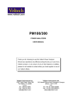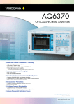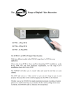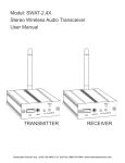
1
BELAR
FMCS-1
ALL-IN-ONE
FM MODULATION MONITOR
Guide to Operations
©2012
BELAR ELECTRONICS
LABORATORY, INC.
119 LANCASTER AVENUE ● P.O. BOX 76 ● DEVON, PA 19333-0076 USA
VOICE (610) 687-5550 ● FAX (610) 687-2686
www.belar.com ● [email protected] ● [email protected] ● [email protected]
WARRANTY, FACTORY RECALIBRATION AND FACTORY SERVICE
FOR ASSISTANCE:
CONTACT YOUR BELAR SALES REPRESENTATIVE
CUSTOMER SERVICE AT THE BELAR FACTORY.
Immediately upon receiving your equipment, please make a careful inspection for any shipping damage. If damage is found or
suspected, please notify the carrier at once and then contact your dealer or the BELAR factory. We strongly encourage you to
save the shipping carton and shipping materials supplied with your equipment. They are specially designed to properly protect
your equipment, and in the event that you need to return it for service, only these OEM shipping materials can ensure its safe
return to our factory.
All BELAR products are warranted against defects in materials and workmanship. This warranty applies for one year from the
date of delivery, FOB factory or, in the case of certain major components listed in the instruction manual, for the specified
period. BELAR will repair or replace products which prove to be defective during the warranty period provided that they are
returned to BELAR pre-paid. No other warranty is expressed or implied. BELAR is not liable for consequential damages.
A RETURN MATERIAL AUTHORIZATION NUMBER MUST BE OBTAINED FROM BELAR IN
ADVANCE OF RETURN.
$ Please call (610-687-5550) or email ([email protected]) to request an RMA number to display on the outside of your
shipping carton and all paperwork.
$ A written statement with the name, address, telephone number & email address together with a brief description of the
work requested, must accompany all returns.
$ The customer shall be responsible for all costs of transportation and insurance to and from the BELAR factory, and all
such costs must be prepaid.
PLEASE VISIT: WWW.BELAR.COM AND REGISTER YOUR PRODUCT SO WE MAY KEEP YOU
INFORMED OF THE LATEST HARDWARE AND SOFTWARE UPDATES.
We no longer ship PC Control Software with the units. Please visit www.belar.com and download the latest WizWin and
Server PC Control Software. Software updates will be posted on our website periodically. The FMCS-1 can be updated in the
field using the PC Software.
Table of Contents
1.
General Information .......................................................................................................................................................1
2.
Front Panel .....................................................................................................................................................................2
3.
Rear Panel.......................................................................................................................................................................3
4.
Main Tuning Screen ........................................................................................................................................................4
5.
dB Readings Screen .........................................................................................................................................................5
6.
Stereo Bargraph Screen...................................................................................................................................................5
7.
SCA Bargraph Screen .......................................................................................................................................................6
8.
Total dB Bargraph Screen ................................................................................................................................................6
9.
Separation Bargraph Screen ............................................................................................................................................7
10.
Crosstalk Bargraph Screen ..........................................................................................................................................7
11.
RF Spectrum Screen ....................................................................................................................................................8
12.
Composite Spectrum Screen .......................................................................................................................................8
13.
Audio Spectrum Screen ..............................................................................................................................................9
14.
RDS Basic Data Screen ..............................................................................................................................................10
15.
Alarms/Relay Screen ................................................................................................................................................11
16.
Popup Menus ...........................................................................................................................................................12
16-1.
RF Popup Menu ........................................................................................................................................................... 12
16-2.
Composite Popup Menu .............................................................................................................................................. 13
16-3.
SCA Popup Menu ......................................................................................................................................................... 13
16-4.
RF Spectrum Popup Menu ........................................................................................................................................... 14
16-5.
Composite Spectrum Popup Menu ............................................................................................................................. 14
16-6.
Audio Spectrum Popup Menu ..................................................................................................................................... 15
16-7.
Unit Settings Popup Menu .......................................................................................................................................... 15
16-8.
Output Settings Popup Menu ...................................................................................................................................... 16
16-9.
Network Status Popup Menu ...................................................................................................................................... 16
16-10.
Network Configure Popup Menu ............................................................................................................................ 17
16-11.
Email Settings Popup Menu .................................................................................................................................... 17
16-12.
Info Settings Popup Menu ...................................................................................................................................... 18
17.
Software Setup and Unit Update Information...........................................................................................................19
17-1.
Connecting to the unit using the RJ-45 Network Jack ................................................................................................. 19
17-2.
Connecting to the unit using the RS-232 Port ............................................................................................................. 19
17-3.
Updating the FMCS-1 Firmware .................................................................................................................................. 19
17-4.
Updating the FMCS-1 Lantronix Ethernet Controller .................................................................................................. 19
FMCS-1 Monitor
1.
GENERAL INFORMATION
Description
The FMCS-1 provides a complete solution for the Analog portions of the FM signal. The unit
combines the features and functions of an RF amplifier, FM demod, stereo demod, RDS decoder,
SCA decoder, and FFT spectrum analyzer in one product. Using state of the art DSP techniques all
of the FMCS-1 processing takes place in the digital domain, this results in FM analog
performance that was previously not possible.
Features
Frequency Agile RF input
AM & Sync AM Noise measurements
HD RF carrier rejections filters to improve analog readings in the presence of HD carriers.
FM Demodulation with 100dB 75 µsec SNR
Variable Bandwidth Composite Filtering
Stereo Demodulation with 100dB L/R Separations
Full metering of Analog Peak and RMS values
RDS Injection/Phase and Full Data decoding
Two SCA Decoders
RF, Composite, and Audio FFT Spectrum Analysis
RJ-45 Ethernet Interface with remote PC software
BELAR ELECTRONICS LABORATORY, INC.
Page 1
FMCS-1 Monitor
2.
FRONT PANEL
The FMCS-1 front panel consists of a 640x240 pixel color LCD display, a rotary encoder with
push switch and a headphone jack. To change screens rotate the encoder, to select a screen and
change any available parameters push on the knob. Once a screen is selected use the cursor to
select the parameters on a given screen, to change a parameter select and click on it. Selected
parameters change from yellow to green. When finished, click again to return to the cursor for that
screen, to exit the screen select the
icon and click it. The encoder now returns to changing
screens.
To access the popup menus press and hold down the encoder for 2 seconds. To navigate the popup
menus rotate the encoder to highlight a menu choice and click the encoder. To exit the pop menu
at any time, hold down the encoder for 2 seconds.
The headphone jack is assignable to any available audio source. To assign the left and right
channels see the Outputs popup menu under Settings.
Page 2
FMCS-1
FMCS-1 Monitor
3.
REAR PANEL
High Level RF Inputs ............................................................................................................... 87.5 to 108.0 MHz, 0.5 to 5.0 Vrms, 50Ω, BNC connector
Antenna Input ............................................................................................................................. 87.5 to 108.0 MHz, 100µV sensitivity, 75Ω, F connector
Analog Composite Outputs ................................................................................................. 1.5 Vrms @ 100% = 75 kHz deviation, 75Ω, BNC connector
Digital Composite Outputs ....................................................................................................... LVDS encoded SCLK, FS, and SDATA, RJ-45 connector
AES-3ID Outputs ............................................................................................................................ AES encoded audio, 1.0Vpk-pk, 75Ω, BNC connector
Analog Audio Outputs ........................................................................................................................................ +10dBm, 600Ω balanced, XLR connector
RS-232 Connector .......................................................................................................................................................................... Male, 9 pin D connector
PIN #
Type
Description
PIN #
Type
Description
1
Input
CTX
4
Output
RTS
2
Input
RX
5
Ground
GND
3
Output
TX
6-9
N/C
Ethernet Connector .....................................................................................................................................................................................................RJ-45
Remote Alarm Connector ....................................................................................................................................................... Female, 15 pin D connector,
................................................................................................................................... Form C Relay contacts rated at 10W max, 0.5A max, 200 VDC max.
PIN #
Relay #
Description
PIN #
Relay #
Description
1
1
CM
8
3
NC
2
1
NC
9
3
NO
3
1
NO
10
4
CM
4
2
CM
11
4
NC
5
2
NC
12
4
NO
6
2
NO
13-15
N/A
N/A
7
3
CM
BELAR ELECTRONICS LABORATORY, INC.
Page 3
FMCS-1 Monitor
4.
MAIN TUNING SCREEN
SCREEN DISPLAY DATA
Total Peak Indicator:
Total Peak Modulation
Pilot Presence Indicator:
Pilot Tone Presence
RDS Presence Indicator:
RDS Carrier Presence
RDS Sync Indicator:
Indicates the RDS decoder has synced to the RDS data stream as is decoding data
SCA#1 Presence Indicator:
SCA#1 Carrier Presence
SCA#1 Peak Indicator:
SCA#1 Peak Modulation
SCA#2 Presence Indicator:
SCA#2 Carrier Presence
SCA#2 Peak Indicator:
SCA#2 Peak Modulation
Total, Left, Right, L+R, L-R:
Peak Modulation Data
Pilot Injection, Pilot Modulation: Pilot Injection Level, Pilot Modulation represents the AM modulation present on Pilot. This is an indication of offthe-air reception quality or multi-path.
RDS Injection: RDS Injection Level
SCA#1 Injection, SCA#1 Peak, SCA#2 Injection, SCA#2 Peak: SCA Injection Level, SCA Peak Modulation is normalized to 100% to a selectable
1.0-7.0 kHz deviation.
RF Level: Indicates signal strength in dB for Antenna input, or percent of full scale input level for High Level inputs. To adjust the RF input level, use
the RF attenuator to bring the signal into the green region for proper operation. For both High Level and Antenna Inputs the RF Level indicates yellow
for low signal level values, green for normal levels, and red for overload levels.
SCREEN SELECTABLE DATA
To select a parameter click on the screen, then use the cursor to select the parameter using the knob, and click again. Adjust the parameter using the
knob and click to set the new value.
To exit this screen, select the screen icon
and return to the screen selection mode.
(in the upper right corner of the screen) and push the rotary encoder dial to exit the screen command mode
Tuning Frequency: Selects the Tuning frequency of the FMCS-1 in 100 kHz steps. The unit tunes to the new frequency as the frequency is changed.
RF Attenuator: Adjusts RF input attenuator in 0.5dB steps from 0.0 to −31.5dB of attenuation. There are separate attenuators from the High Level and
Antenna Inputs.
Page 4
FMCS-1
FMCS-1 Monitor
5.
DB READINGS SCREEN
The dB readings screen contains all the dB RMS readings performed in the FMCS-1, the readings in white are de-emphasized, the yellow readings are
flat or wideband.
SCREEN DISPLAY DATA
RF Level: Depending on which RF Input is selected displays the dB level at the A/D Input, the input begins overloading at +3.0dB.
AM Noise: AM modulation present on the FM carrier, this reading is de-emphasized by definition.
SYNC Noise: AM modulation present on the FM carrier, this reading is wideband.
Total, Pilot, 38 kHz, L, R, L+R, L-R: All readings are referenced to 0dB = 100% modulation or 75 kHz deviation.
Sep, XTalk: Separation and Crosstalk readings are the difference between the flat Left and Right, or L+R and L-R readings.
SCREEN SELECTABLE DATA
None
6.
STEREO BARGRAPH SCREEN
SCREEN DISPLAY DATA
Total, Pilot, Left, Right, L+R, and L-R: Peak Modulation bar graphs display the Peak (Red), Average (Yellow), and Min (Green) modulation data.
All readings a referenced to 100% at 75 kHz deviation.
SCREEN SELECTABLE DATA
None
BELAR ELECTRONICS LABORATORY, INC.
Page 5
FMCS-1 Monitor
7.
SCA BARGRAPH SCREEN
SCREEN DISPLAY DATA
RDS Injection: RDS subcarrier injection as measured thru a 57 kHz BPF.
SCA#1 & SCA#2 Injection: SCA Injections are measured thru a user selectable variable bandwidth BPF; see SCA in the popup menus for settings.
SCA#1 & SCA#2 Peak: SCA Peak Modulation bar graphs display the Peak (Red), Average (Yellow), and Min (Green) modulation data. All readings a
referenced to 100% at a user specified deviation which is adjustable from 1.0 to 7.0 kHz. See the SCA popup menu.
All Injection readings are referenced to 100% at 75 kHz deviation.
SCREEN SELECTABLE DATA
None
8.
TOTAL DB BARGRAPH SCREEN
SCREEN DISPLAY DATA
Total Modulation: Total Peak Modulation bar graph displays Peak (Red), Average (Yellow), and Min (Green) modulation data.
Total dB: Total dB bar graph displays Flat (Yellow) and De-Emphasized (Green) dB RMS data.
Pilot dB: Pilot dB bar graph displays the dB RMS value as measured thru the 19 kHz pilot BPF.
38 kHz dB: 38 kHz Subcarrier dB bar graph displays the dB RMS value as measured thru the 38 kHz subcarrier suppression BPF.
All readings are referenced to 100% or 0.0dB at 75 kHz deviation.
SCREEN SELECTABLE DATA
None
Page 6
FMCS-1
FMCS-1 Monitor
9.
SEPARATION BARGRAPH SCREEN
SCREEN DISPLAY DATA
Left & Right Modulation: Peak Modulation bar graph displays Peak (Red), Average (Yellow), and Min (Green) modulation data.
Left & Right dB: dB bar graph displays Flat (Yellow) and De-Emphasized (Green) dB RMS data.
Separation dB: Separation dB bar graph displays the dB RMS value of the difference between the Left and Right Flat dB values. The measurement
assumes the larger signal is the wanted channel verse the lesser unwanted channel and represents the stereo separation.
SCREEN SELECTABLE DATA
None
10.
CROSSTALK BARGRAPH SCREEN
SCREEN DISPLAY DATA
L+R & L-R Modulation: Peak Modulation bar graph displays Peak (Red), Average (Yellow), and Min (Green) modulation data.
L+R & L-R dB: dB bar graph displays Flat (Yellow) and De-Emphasized (Green) dB RMS data.
Crosstalk dB: Crosstalk dB bar graph displays the dB RMS value of the difference between the L+R and L-R Flat dB values. This measurement
assumes the larger signal is the wanted channel verse the lesser unwanted channel and represents the stereo crosstalk.
SCREEN SELECTABLE DATA
None
BELAR ELECTRONICS LABORATORY, INC.
Page 7
FMCS-1 Monitor
11.
RF SPECTRUM SCREEN
The RF spectrum screen displays the RF spectrum centered around the tuning frequency with frequencies above being positive and below being negative.
The amplitude and frequency scales are both adjustable and have cursors associated with them. The RF spectrum is maybe colored such that center
green represents the analog carriers, yellow the main HD carriers, and red the extended mode HD carriers.
SCREEN SELECTABLE DATA
To select a parameter click on the screen, then select the choice using the knob, and click again. Adjust the parameter using the knob and click to set the
new value. To exit this screen, select the screen
icon and click on it.
dB: The dB amplitude scale is scrollable from +100.0dB to −150.0dB in increments of the selected major division.
VR: The dB amplitude resolution is adjustable from 0.1dB to 0.8dB per pixel.
C1: The C1 cursor is a horizontal amplitude cursor which is adjustable in VR steps.
HR: The frequency resolution is adjustable in steps of 50, 100, 250, 500, 1k, 1.5k, 2k, and 2.5 kHz per pixel.
C2: The C2 cursor is a vertical frequency cursor, which displays the amplitude value at the selected frequency. Frequency step size is determined by the
HR setting.
kHz: The spectrum frequency is scrollable in the current major division step size approximately ±1.0MHz around the tuning frequency.
12.
COMPOSITE SPECTRUM SCREEN
The Composite spectrum screen displays the Composite spectrum from 0 to 150 kHz. The amplitude and frequency scales are both adjustable and have
cursors associated with them.
SCREEN SELECTABLE DATA
To select a parameter click on the screen, then select the choice using the knob, and click again. Adjust the parameter using the knob and click to set the
new value. To exit this screen, select the screen
icon and click on it.
dB: The dB amplitude scale is scrollable from +100.0dB to −150.0dB in increments of the selected major division.
VR: The dB amplitude resolution is adjustable from 0.1dB to 0.8dB per pixel.
C1: The C1 cursor is a horizontal amplitude cursor which is adjustable in VR steps.
HR: The frequency resolution is adjustable in steps of 5, 10, 25, 50, 125, and 250 Hz per pixel.
C2: The C2 cursor is a vertical frequency cursor, which displays the amplitude value at the selected frequency. Frequency step size is determined by the
HR setting.
kHz: The spectrum frequency is scrollable in the current major division step size over the entire 0 to 150 kHz range.
Page 8
FMCS-1
FMCS-1 Monitor
13.
AUDIO SPECTRUM SCREEN
The Audio spectrum screen displays the Audio spectrums from 0 to 24 kHz. The amplitude and frequency scales are both adjustable and have cursors
associated with them.
SCREEN SELECTABLE DATA
To select a parameter click on the screen, then select the choice using the knob, and click again. Adjust the parameter using the knob and click to set the
new value. To exit this screen, select the screen
icon and click on it.
dB: The dB amplitude scale is scrollable from +100.0dB to −150.0dB in increments of the selected major division.
VR: The dB amplitude resolution is adjustable from 0.1dB to 0.8dB per pixel.
C1: The C1 cursor is a horizontal amplitude cursor which is adjustable in VR steps.
HR: The frequency resolution is adjustable in steps of 1, 2, 5, 10, 25 and 50 Hz per pixel.
C2: The C2 cursor is a vertical frequency cursor, which displays the amplitude value at the selected frequency. Frequency step size is determined by the
HR setting.
kHz: The spectrum frequency is scrollable in the current major division step size over the entire 0 to 24 kHz range.
BELAR ELECTRONICS LABORATORY, INC.
Page 9
FMCS-1 Monitor
14.
RDS BASIC DATA SCREEN
The basic RDS data screen displays data encoded on the 57 kHz RDS subcarrier from the RDS decoder.
SCREEN DISPLAY DATA
PI: Program Identification Code
PS: Program Service Name
PTY: Program Type
PTYN: Program Type Name
TP: Traffic Program
TA: Traffic Announcement
MS: Music/Speech Program
Time & Date: Current Encoded Time and Date
DI: Decoder Identification
PIN: Program Item Number
Radio Text: Up to 64 characters of text, Embedded carriage Returns and Line Feeds are displayed as CR and LF characters
Alternate Frequencies: Frequencies of neighboring transmitters or repeater stations
Group Types: Displays all the RDS Group types currently being broadcast
SCREEN SELECTABLE DATA
None
Page 10
FMCS-1
FMCS-1 Monitor
15.
ALARMS/RELAY SCREEN
SCREEN SELECTABLE DATA
To select a parameter click on the screen, then select the event using the knob, and click again. Use the encoder to select the event parameter and click,
set the new value, and click again. To exit the event, select it, and click. The events scroll as the cursor is moved thru the list. To exit this screen, select
the screen
icon and click on it.
Events can be set to trigger any one of four relay closures, 4 email addresses, or display in a popup alarm window on the FMCS-1.
Alarm Status is indicated with a multi-colored graphical LED. Red indicates the alarm is active, yellow indicates the alarm has met the threshold but not
the time criterion, green indicates no alarm condition.
Loss of RF (ANT): Loss of RF on Antenna Input, Threshold −10.0 to −80dB; Time 1 to 60 sec
Loss of RF (HL): Loss of RF on High Level Input, Threshold 0 to 100.0%; Time 1 to 60 sec
High AM Noise: High AM Noise Level, Threshold −20.0 to −80.0dB; Time 1 to 60 sec
High SYNC Noise: High AM Synchronous Noise Level, Threshold −20.0 to −80.0dB; Time 1 to 60 sec
Loss of Total: Loss of Peak Total Modulation, Threshold 0 to 100.0%; Time 1 to 60 sec
Total Peak LED: Total Peak Level Exceeded, Threshold 0 to 150.0%; Time N/A
Loss of L+R: Loss of L+R or Mono program, Threshold 0 to 100.0%; Time 1 to 60 sec
Loss of Pilot: Indicates Pilot Tone is present, Threshold 0 to 15.0%; Time 1 to 60 sec.
Loss of RDS: Indicates RDS subcarrier is present, Threshold 0 to 10.0%; Time 1 to 60 sec
Loss of RDS SYNC: Indicates RDS decoder has synced to RDS data stream and is decoding data, Threshold N/A; Time 1 to 60 sec
Loss of SCA#1: Indicates SCA#1 subcarrier is present, Threshold 0 to 25.0%; Time 1 to 60 sec
SCA#1 Peak LED: SCA#1 Peak Modulation Level Exceeded, Threshold 0 to 150.0%; Time 1 to 60 sec
Loss of SCA#2: Indicates SCA#2 subcarrier is present, Threshold 0 to 25.0%; Time 1 to 60 sec
SCA#2 Peak LED: SCA#2 Peak Modulation Level Exceeded, Threshold 0 to 150.0%; Time 1 to 60 sec
BELAR ELECTRONICS LABORATORY, INC.
Page 11
FMCS-1 Monitor
16.
POPUP MENUS
Many of the FMCS-1 Parameters and Information are accessed using popup menus. To access the popup menus press and hold down the
encoder for 2 seconds. To navigate the popup menus rotate the encoder to highlight a menu choice and click the encoder. To exit the pop menu
at any time, hold down the encoder for 2 seconds.
RF:
Settings which affect the RF portion of the signal.
Composite:
Settings which affect the Composite or baseband part of the signal.
SCA:
Subcarrier settings for SCA#1 and SCA#2.
Spectrum:
RF, Composite, and Audio spectrum settings.
Settings:
Unit, outputs, and network settings and information.
16-1.
RF POPUP MENU
Input Select: Select which RF input is used Antenna (off the air) or High Level (tx site).
Tuning: Allows frequency tuning of the unit from any screen.
Calibrator: Activates internal RF calibrator. Calibrate waveforms: off, zero (un-modulated carrier), mono 1kHz(1 kHz sine wave 75 kHz deviation), left
1 kHz (1 kHz 90% left only), left 5 kHz(5 kHz 90% left only), left 10 kHz (10 kHz 90% left only), left 15 kHz (15 kHz 90 left only), SCA 67 92 zero
(un-modulated 67 kHz and 92 kHz subcarriers at 10% injection), and SCA 67 92 1 kHz (1 kHz modulated 67 kHz and 92 kHz subcarriers , 6 kHz
deviation, 10% injection).
Attenuator: 0.0 to −31.5dB step attenuator adjustable in 0.5dB steps. There are separate attenuators on both the Antenna and High Level inputs, the
input select determines which attenuator is active.
Filter: RF filter which affects all analog readings. Filter choices: wideband, HD −25DB MP1, HD −25dB MP3, HD −50dB MP1, and HD −50dB MP3.
Wideband mode should be used for the most accurate readings, except in the presence of HD carriers which introduce interference into the demodulated
analog signal. If HD carries are present, the HD −25dB filter is recommended to suppress the HD carriers, choose the MP mode based on the HD service
mode being broadcast. The HD −50dB filters are recommended when making AM noise measurements in the presence of HD carriers or when running
elevated HD carrier power.
Mute: Mutes composite and audio outputs. In addition to manually turning the mute on or off, auto muting is done based on the thresholds for the high
level and antenna inputs on the alarm/relay screen.
Page 12
FMCS-1
FMCS-1 Monitor
16-2.
COMPOSITE POPUP MENU
Filter BW: Selects Composite filter bandwidth: Stereo + RDS (passes stereo plus 57 kHz RDS), Stereo + 67 KHz (passes stereo thru 67 kHz SCA, and
Stereo + 92 kHz (passes stereo thru 92 kHz SCA), and wideband. To reduce the interference from off-air-noise or HD carriers it is recommended that the
Composite filter bandwidth be set as low as possible depending on the SCA’s present.
Peak Mod: Adjusts the threshold for the Total peak light on the Main Tuning Screen. When the threshold is exceeded, the red peak flasher will signal the
condition.
16-3.
SCA POPUP MENU
The FMCS-1 contains two independent SCA decoders SCA#1 and SCA#2. The parameters and setup of these decoders are the same so only one will be
described.
BPF Bypass: SCA BPF bypass. When OFF the selected BPF filter is applied to the SCA before demodulation, ON removes the BPF which results in
approximately a ±20 KHz bandwidth around the center frequency.
BPF Freq: Adjusts the center frequency of the SCA BPF filter, adjustable from 41.0 to 92.0 kHz in 0.1 kHz steps.
BPF BW: Selects the SCA BPF bandwidth around the center frequency. The range is 1.0 to 16 kHz in 1 kHz steps.
DET Mod: Specifies the type of detector used to demodulate the SCA. Choices are FM or None.
DET Resp: The Detector Response maybe be set to Flat, 75 µsec, or 150 µsec.
DET BW: Selects the Detectors LPF bandwidth, choices are 1.0 to 8.0 kHz in 1.0 kHz steps.
DET Norm: Adjusts the normalization used to scale the modulation readings. The range is 1.0 to 7.0 kHz in 0.1 kHz steps. The normalization is typically
set to the maximum deviation of the SCA carrier; this normalizes the SCA peak reading for 100% @ max SCA deviation.
SET Peak: Sets the SCA Peak Indicator limit. When this value is exceeded, the SCA peak indicator on the Man Tuning Screen will turn red. Range is
0.0 to 150.0% in 1.0% steps.
SET Mute: Selects how the Mute function is applied to the SCA readings and Audio output. The Mute may be turned OFF (no muting), ON (always
muted), or AUTO (based on the SET Thres).
SET Thres: Adjusts the threshold for the Mute and SCA Presence Indicator on the Main Tuning Screen. Range is 0.0 to 25.0% of SCA injection in 0.1%
steps.
BELAR ELECTRONICS LABORATORY, INC.
Page 13
FMCS-1 Monitor
16-4.
RF SPECTRUM POPUP MENU
Display Mode: The Display Mode affects how the spectrum data is presented, in Realtime mode the spectrum is updated with new data each time, Peak
Hold displays the highest value in the last Hold Count value of spectrums, Average displays the average of the last Average Count of spectrums, and
Infinite holds the highest values until reset.
Hold Count: Determines how many spectrums are used to compute the maximum values at each data point when the Display Mode = Peak Hold.
Avg Count: Sets how many spectrum are used to compute the spectrum average when the Display Mode = Average.
0dB Ref Lev: The 0dB Reference Level normalizes the 0dB point on the spectrum display to a specific dB value.
Curve Fill: Determines whether the spectrum display is a signal line or filled in from the bottom up.
Colors: Changes the normally green spectrum display into a multi-color display with green representing the analog portion, yellow the normal HD
carriers, and red the extended HD carriers.
Mask: Enables the RF spectral mask defined for HD radio.
Measurements: Enables any additional measurements associated with the spectrum.
16-5.
COMPOSITE SPECTRUM POPUP MENU
Display Mode: The Display Mode affects how the spectrum data is presented, in Realtime mode the spectrum is updated with new data each time, Peak
Hold displays the highest value in the last Hold Count value of spectrums, Average displays the average of the last Average Count of spectrums, and
Infinite holds the highest values until reset.
Hold Count: Determines how many spectrums are used to compute the maximum values at each data point when the Display Mode = Peak Hold.
Avg Count: Sets how many spectrum are used to compute the spectrum average when the Display Mode = Average.
0dB Ref Lev: The 0dB Reference Level normalizes the 0dB point on the spectrum display to a specific dB value.
Curve Fill: Determines whether the spectrum display is a signal line or filled in from the bottom up.
Colors: Changes the normally green spectrum display into a multi-color display.
Measurements: Enables any additional measurements associated with the spectrum.
Page 14
FMCS-1
FMCS-1 Monitor
16-6.
AUDIO SPECTRUM POPUP MENU
Input Type: Selects a single or dual input spectrum.
Input #1: Input Select #1 determines the input source used for all single spectrums and channel #1 of dual spectrums.
Input #2: Input Select #2 determines the input source for channel #2 of dual spectrums.
Display Mode: The Display Mode affects how the spectrum data is presented, in Realtime mode the spectrum is updated with new data each time, Peak
Hold displays the highest value in the last Hold Count value of spectrums, Average displays the average of the last Average Count of spectrums, and
Infinite holds the highest values until reset.
Hold Count: Determines how many spectrums are used to compute the maximum values at each data point when the Display Mode = Peak Hold.
Avg Count: Sets how many spectrum are used to compute the spectrum average when the Display Mode = Average.
0dB Ref Lev: The 0dB Reference Level normalizes the 0dB point on the spectrum display to a specific dB value.
Curve Fill: Determines whether the spectrum display is a signal line or filled in from the bottom up.
Colors: Changes the normally green spectrum display into a multi-color display.
Measurements: Enables any additional measurements associated with the spectrum.
16-7.
UNIT SETTINGS POPUP MENU
Time Mode: The Time Mode affects all the peak modulation readings and bar graphs. In Real Time Mode when a peak exceeds the current displayed
peak the value is updated immediately to the new value and held for the Hold Time, until either a new peak is detected or the Hold Time is met. In Past
Time Mode, the unit waits the Hold Time and displays the highest peak which was detected during that time period.
Hold Time: Adjusts the Peak Hold Time from 0.25 to 0.5 - 5.0 seconds in 0.5 second increments.
Infinite: When Infinite Hold is enabled, the highest peak values are held until disabled. Infinite Hold affects all the modulation readings and bar graphs.
Units: The units for modulation data may be displayed in either% where 100% = 75 kHz deviation, or directly in kHz deviation.
De-Emphasis: Sets the De-Emphasis for all de-emphasized readings to either 50 µsec or 75 µsec.
Filter Response: Selects the Left, Right, L+R, and L-R frequency response. The normal setting uses the standard 15 kHz bandwidth for readings and
audio outputs. The extended option increases the filter bandwidth to 16.5 KHz. Extending the filter response can result in more accurate L, R, L+R, and
L-R peak modulation readings. This is dependent on the audio programming and processor settings.
Remote: Allows or blocks remote connections to the unit via the RS-232 or RJ-45 connector.
Screen Saver: The Screen Saver turns off the LCD’s backlight after a specified period without any encoder activity. The choices are off, and 1 to 12
hours in 1 hour increments.
Reset Defaults: To reset the unit back to factory defaults click on the Reset Defaults Button.
Reboot: To reboot the unit click on the Reboot Button.
BELAR ELECTRONICS LABORATORY, INC.
Page 15
FMCS-1 Monitor
16-8.
OUTPUT SETTINGS POPUP MENU
The FMCS-1provides 8 channels of analog audio output, 8 channels of AES/EBU output, and a headphone output. Any one of these output jacks maybe
assigned any of the available audio: Mute, L, L(*), R, R(*), L+R, L+R(*), L−R, L−R(*), SCA#1, SCA#2 ,Pilot, Test 0dB, Test −3dB, and Test −6dB. The
(*) is the de-emphasized audio, otherwise the audio is flat. The SCA#1 and SCA#2 audio de-emphasis is selected in the SCA pop up window. The Test
waveforms are a 1 kHz sine wave at 0, −3, and −6dBFS.
Analog CH#1−CH#8: Routes the specified audio source to the selected Analog Channel.
AES/EBU CH#1−CH#8: Routes the specified digital audio source to the selected AES/EBU Channel.
Headphone L and R: Assigns the audio program to the headphone Left and Right channels.
Headphone Volume: Sets the Headphone volume, range is 1 to 100% in 1% steps.
16-9.
NETWORK STATUS POPUP MENU
MAC: MAC address of the FMCS-1.
Host: The Hostname of the FMCS-1.
IP Address: IP Address assigned to the unit.
Subnet: Subnet address.
Gateway: Gateway address.
DHCP: Status of DHCP.
Refresh: To refresh the network status information click on the Refresh button.
Page 16
FMCS-1
FMCS-1 Monitor
16-10.
NETWORK CONFIGURE POPUP MENU
IP Address: DHCP must be disabled to enter a static IP
Subnet: DHCP must be disabled to enter a Subnet
Gateway: DHCP must be disabled to enter a Gateway
DHCP: Enables or Disables DHCP. If DHCP is enabled the IP, Subnet, and Gateway addresses will be assigned automatically by the DHCP server. To
set a static IP address DHCP must be disabled.
Apply: To apply network configuration changes click the Apply button.
Status: Displays the status of the Lantronix when a new configuration is being applied.
16-11.
EMAIL SETTINGS POPUP MENU
TO: Email address to which email alerts will be sent. 24 characters max. This field must be set.
CC: Optional email address to which email alerts will be copied. 24 characters max
FROM: Email address alerts will be sent from. 24 characters max. This field must be set.
SUBJECT: Email subject prefix. 12 characters max.
Test: To send a test email click on the Test button.
BELAR ELECTRONICS LABORATORY, INC.
Page 17
FMCS-1 Monitor
16-12.
INFO SETTINGS POPUP MENU
BOOT: Processor Boot Code Version and Date.
MAIN: Processor Main Code Version and Date.
DSP#1-DSP#6: Digital Signal Processors #1 thru #6 Code Versions and Dates.
MICRO: Micro Processor Code Version and Date.
UNIT: Unit configuration.
SERIAL #: The unit’s serial number.
Page 18
FMCS-1
FMCS-1 Monitor
17.
SOFTWARE SETUP AND UNIT UPDATE INFORMATION
The FMCS-1 maybe connected to a computer using the BELAR WizWin Software, which can be downloaded from our
website at www.belar.com. Connections can be made using the RS-232 port or Ethernet connectors on the rear panel. In
addition to accessing the unit remotely, the WizWin Software may also be used to update the FMCS-1 firmware in the field.
Please check our website at www.belar.com for the latest software updates as we are always improving our products and
adding features.
17-1.
CONNECTING TO THE UNIT USING THE RJ-45 NETWORK JACK
1. Download and Install the latest version of BELAR WizWin Software from our website.
2. If connecting to a network with a DHCP server in place (the FMCS-1 is shipped with DHCP enabled) connect the
FMCS-1 to your network, on the same subnet as the computer you loaded the WizWin Software, and power cycle
the unit.
3. If your network does not have a DHCP server, the FMCS-1 will select an APIPA (Automatic Private IP Address)
address in the 169.254.xxx.xxx range with a 255.255.0.0 subnet. You can then use an isolated (non DHCP) switch or
a crossover cable to connect the FMCS-1 to your computer. You must set the computer IP to the same
169.254.xxx.xxx range with the 255.255.0.0 subnet. (Most computers set to DHCP enabled will default to an APIPA
address if no DHCP server is present when they are booted up).
4. To obtain the Units IP address on the FMCS-1, activate the popup menu and select Settings, under Settings select the
Network:Status submenu to display the current network information. Make sure that the FMCS-1 is power cycled
after the RJ-45 cable has been connected to the unit.
5. Run the WizWin Software and select “Connections” from the window. A pop-up dialog box will appear, select
“Connection #1” and click the “Configure” Button. Using the tabs in the Configuration Dialog Box set the
“Hardware Type” to “FMCS-1”, set the “Connection Type” to “Network- Ethernet”, and under “Network” set the
“IP Address” to the address displayed on the FMCS-1, then set the “PORT” to “10001”, click the “Save” Button to
finish. Finally, click the “Connect” Button and the unit will connect and display a virtual front panel of the unit.
17-2.
CONNECTING TO THE UNIT USING THE RS-232 PORT
1. Download and Install the latest version of BELAR WizWin Software from our website.
2. Connect the unit to the computer using a 9-pin serial modem cable.
3. Run the WizWin Software and select “Connections” from the window. A pop-up dialog box will appear, select
“Connection #1” and click the “Configure” Button. Using the tabs in the Configuration Dialog Box set the
“Hardware Type” to “FMCS-1”, set the “Connection Type” to “RS-232”, under “RS-232” set the “COM Port” to the
COM Port being used on the computer, click the “Save” Button to finish. Finally, click the “Connect” Button and the
unit will connect and display a virtual front panel of the unit.
17-3.
UPDATING THE FMCS-1 FIRMWARE
Establish a computer connection to the unit using either the RS-232 Port or the RJ-45 Ethernet Jack. See the previous
instructions for connecting to the FMCS-1.
With the WizWin Software running and connected to the FMCS-1 the virtual front panel of the unit should be visible. In the
“Connections” Dialog Box click the “Update” Button, a “Update” Dialog Box will appear showing the FMCS-1 units current
software version and the Files software version. A warning message will appear if the File software version is the same or
older than what is currently in FMCS-1 unit. To start the update click the “Update EPROM” Button, the front panel of the
FMCS-1 will show the update status.
17-4.
UPDATING THE FMCS-1 LANTRONIX ETHERNET CONTROLLER
The Lantronix Ethernet Controller should be updated to version 4.0.0.0 for proper operation of the unit. Establish a computer
connection to the unit using either the RS-232 Port or the RJ-45 Ethernet Jack. See the previous instructions for connecting to
the FMCS-1.
With the WizWin Software running and connected to the FMCS-1 the virtual front panel of the unit should be visible. In the
“Connections” Dialog Box click the “Update” Button, a “Update” Dialog Box will appear showing the FMCS-1 Lantronix
current software version and the Files software version. To start the update click the “Update Lantronix” Button, the front
panel of the FMCS-1 will show the update status.
BELAR ELECTRONICS LABORATORY, INC.
Page 19
BELAR
ELECTRONICS LABORATORY, INC.
119 LANCASTER AVENUE
P.O. BOX 76
DEVON, PA 19333 USA
VOICE (610) 687-5550 ● FAX (610) 687-2686
www.belar.com
[email protected]
[email protected]
[email protected]