1
38YLS...G Installation instructions supplement
ENGLISH
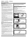
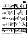
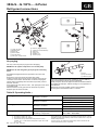
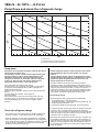
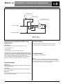
Head pressure controller: wiring from temperature sensor to printed circuit board
Sensor
Sensor
Sensor
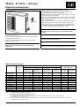
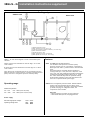
Head pressure controller and HIP remote
manual reset
Temperature setting
Proportional band
set point +11 / –11°C
Minimum speed output voltage:
125 V
• Printed circuit board, with electronic components and quick
connector terminals.
Setting:
the head pressure controller is
supplied factory set at 42°C
• Temperature sensor, complete with 500 mm wiring.
Hard start time
3 seconds.
Configuration
The head pressure control “HPC” is made of two parts:
The high pressure switch “HIP” has been selected at automatic reset.
If “HIP” trips, cycle the power supply OFF and ON to reset the system,
because the electrical box is equipped with relays that prevent the
unit from starting, until the indoor control is switched OFF.
When head pressure drops below 3000 kPa (30 bar; 420 psig) it is
possible to restart the unit switching the indoor control ON.
Troubleshooting
See paragraph “Troubleshooting”.
Operations mode
Full voltage:
If the liquid line temperature is above the setpoint value plus half
the proportional band (factory set by supplier), the output voltage to
the motor is 97% or more of supply voltage.
Note:
At start-up or in case of re-start after a pause of several hours
at – 15°C, with low voltage supply (198V) high pressure switch
HIP may trip off the unit. In this case, the remote reset by indoor
control (infrared) can be done for unit restarting.
Low voltage:
If the liquid line temperature is below set point minus half the
proportional band, the output voltage to the motor is fixed to 125V.
Hard start:
At each compressor starting the full voltage output to the fan motor
is provided for 3 seconds.
Proportional band:
The controller directly senses the changes in liquid line temperature
and varies the output voltage which causes the fan motor speed
increase or decrease.
GB - 17