1
Table of Contents
Table of Contents
Chapter 1. Introduction..............................................................................................6
FEATURES........................................................................................................................................6
HARDWARE/SOFTWARE REQUIREMENTS......................................................................................7
INSTALLING THEATERTOUCH DESIGNER.................................................................. 7
Chapter 2. Programming Overview.........................................................................8
CREATING A SYSTEM STEP BY STEP.............................................................................................8
THEATERTOUCH DESIGNER SCREENS...........................................................................................9
DESIGN GUIDELINES.....................................................................................................................17
GETTING HELP..............................................................................................................................17
Chapter 3. Working with System Files................................................................18
INTRODUCTION TO SYSTEM FILES..............................................................................................18
CREATING A NEW FILE..................................................................................................................18
OPENING AN EXISTING FILE.........................................................................................................19
SAVING A FILE...............................................................................................................................19
EDITING SYSTEM PROPERTIES....................................................................................................20
Chapter 4. Working with Devices...........................................................................21
INTRODUCTION TO DEVICES........................................................................................................21
ADDING A DEVICE.........................................................................................................................21
IMPORTING A DEVICE...................................................................................................................21
DELETING A DEVICE......................................................................................................................22
RENAMING A DEVICE....................................................................................................................22
DUPLICATING A DEVICE................................................................................................................23
CLOSING A DEVICE.......................................................................................................................23
SAVING A DEVICE..........................................................................................................................23
EDITING A DEVICE.........................................................................................................................23
EDITING DEVICE PROPERTIES......................................................................................................24
Chapter 5. Working with Pages..............................................................................65
INTRODUCTION TO PAGES...........................................................................................................65
ADDING A PAGE (K4/RK3/T4/T3/T2+) .........................................................................................69
DELETING A PAGE (K4/RK3/T4/T3/T2+)........................................................................................69
DUPLICATING A PAGE (K4/RK3/T4/T3/T2+)..................................................................................69
RENAMING A PAGE.......................................................................................................................70
INSERTING AND DELETING FRAMES (T2+) . ...............................................................................71
INSERTING A PRE-DEFINED PAGE (K4/RK3/T4/T3/T2+)...............................................................71
LINKING A PAGE TO A BUTTON ...................................................................................................72
REMOVING A PAGE LINK..............................................................................................................72
MERGING PAGES (K4/RK3/T4/T3/T2+).........................................................................................73
3
TheaterTouch Designer
Chapter 6. Working with Buttons.........................................................................74
INTRODUCTION TO BUTTONS.......................................................................................................74
DRAWING BUTTONS.....................................................................................................................74
SELECTING BUTTONS...................................................................................................................75
DELETING BUTTONS.....................................................................................................................76
CHANGING BUTTON STYLES........................................................................................................76
USING THE GRID (K4/RK3/T4/T3).................................................................................................76
ARRANGING BUTTONS (K4/RK3/T4/T3).......................................................................................77
MOVING BUTTONS (K4/RK3/T4/T3/T2+).......................................................................................77
MOVING BUTTONS (K4/RK3/T4/T3)..............................................................................................77
RE-SIZING BUTTONS.....................................................................................................................78
EDITING BUTTON TEXT.................................................................................................................79
ADDING BITMAPS TO BUTTONS . ................................................................................................80
CUSTOM BUTTONS AND BITMAPS (T2+) . ..................................................................................83
IMAGE EDITORS (T2+) .................................................................................................................84
ADDING A CUSTOM BUTTON (T2+)..............................................................................................90
EDITING A BUTTON'S PROPERTIES..............................................................................................91
EDITING THE PROPERTIES OF MULTIPLE BUTTONS...................................................................98
EDIT MENU FUNCTIONS................................................................................................................99
IMPORTING GRAPHICS (K4/RK3/T4/T3).......................................................................................99
Chapter 7. Working with Commands . ................................................................100
INTRODUCTION TO COMMANDS................................................................................................100
INTRODUCTION TO THE IR LIBRARY MANAGER........................................................................101
CREATING A NEW IR COMMAND LIBRARY ...............................................................................102
OPENING AN EXISTING IR .........................................................................................................102
COMMAND LIBRARY . ................................................................................................................102
IMPORTING AN IR COMMAND LIBRARY....................................................................................103
EXPORTING AN IR COMMAND LIBRARY....................................................................................103
ADDING A NEW REMOTE............................................................................................................104
DUPLICATING A REMOTE .........................................................................................................104
RENAMING A REMOTE .............................................................................................................104
DELETING A REMOTE .............................................................................................................105
ADD FUNCTIONS TO A REMOTE ..............................................................................................105
USING THE NEW FUNCTION WIZARD .......................................................................................106
DELETING FUNCTIONS FROM A REMOTE...................................................................................106
EDITING FUNCTIONS IN A REMOTE............................................................................................106
INTRODUCTION TO IR CODES ...................................................................................................107
HINTS FOR LEARNING IR CODES ..............................................................................................108
ADDING IR CODES TO THE IR LIBRARY.....................................................................................109
CAPTURING IR CODES WITH AN IR-PRO LEARNING DEVICE ..................................................110
EDITING IR CODES......................................................................................................................111
VIEWING IR CODES.....................................................................................................................112
UPDATING THE RTI MASTER IR COMMAND LIBRARY...............................................................114
Table of Contents
EXPORT REMOTES TO THE INTERNET.......................................................................................114
ADDING AN IR COMMAND TO A BUTTON..................................................................................115
IR SEARCH & REPLACE..............................................................................................................116
ADDING AN RS-232 COMMAND TO A BUTTON..........................................................................117
Chapter 8. Working with Macros . ......................................................................118
INTRODUCTION TO MACROS......................................................................................................118
USING THE MACRO EDITOR.......................................................................................................118
DELETING A MACRO...................................................................................................................126
EDITING AN INDIVIDUAL STEP IN A MACRO.............................................................................126
UNDERSTANDING SYSTEM MACROS.........................................................................................127
GENERATE IR TRIGGER CODES FOR SYSTEM MACROS............................................................128
USING THE CHANNEL MACRO WIZARD (K4/RK3/T4/T3/T2+)....................................................129
CREATING A NEW SCROLLING LIST (T2+).................................................................................131
Chapter 9. Working with Objects (K4/RK3/T4)..................................................133
INTRODUCTION TO OBJECTS.....................................................................................................133
USING OBJECTS AND COMMANDS............................................................................................134
Chapter 10. TheaterTouch Designer Finishing Touches.............................136
PREVIEWING YOUR FILE.............................................................................................................136
SENDING A PROGRAM TO A DEVICE..........................................................................................137
Chapter 11. TheaterTouch Designer Utilities................................................139
PRINTING PAGES (K4/RK3/T4/T3/T2+).......................................................................................139
PRINTING SYSTEM CONFIGURATION REPORTS........................................................................139
CHECKING MEMORY USAGE.......................................................................................................140
FIRMWARE VERSION..................................................................................................................140
Chapter 12. Troubleshooting...............................................................................141
DISPLAY IS DIM, BLANK OR UNREADABLE...............................................................................141
COMMUNICATION PROBLEMS....................................................................................................141
INFRARED PROBLEMS................................................................................................................142
UNABLE TO LEARN COMMANDS................................................................................................143
MACRO PROBLEMS....................................................................................................................143
Notes...............................................................................................................................144
TheaterTouch Designer
Chapter 1. Introduction
TheaterTouch Designer is a powerful, easy-to-use, Windows based software package that allows an entire
TheaterTouch system to be programmed from a PC. It includes a wide variety of powerful tools that make the
programming process quick and easy.
TheaterTouch Designer provides complete flexibility in the design of the TheaterTouch screen. Several pre-defined
buttons, symbols and page templates are included along with the ability to directly import your own color graphics.
TheaterTouch Designer also includes a powerful Infrared Library Manager. Infrared codes are learned and stored
for easy reuse in multiple systems and are added to any button by a simple drag-and-drop process. Updates to
the included infrared library are continually being made and are available for download from the RTI website.
TheaterTouch Designer Macro Editor provides a simple interface enabling every button in the system to carry out
complex multi-step actions.
The product of over 15 years of development, TheaterTouch Designer is a central part of the TheaterTouch system, not an afterthought. The software is continually being refined, and upgrades are available from the RTI web
site.
FEATURES
• Provides a central interface for defining all parameters needed for controlling an entire TheaterTouch system
• Contains several programming wizards to get you up and running quickly
• Allows programming to be uploaded from existing TheaterTouch systems and edited, in case the original
program is lost or damaged
• Allows for direct importing of your own color graphics with complete flexibility on button size, shape, style,
and labels • Allowsfor direct importing of your own sound files (*.wav) for use with the buttons on color devices • Includes graphics editors for creating Custom Buttons and Bitmaps (for use with the T2+ Universal
Controller)
• Infrared Library allows easy drag-and-drop programming of IR codes on every button
• Includes libraries of predefined IR codes and bitmaps
• Infrared Library Manager allows infrared commands to be learned into libraries and stored for future use
• Macro Editor allows complex multi-step actions to be created on every button
• Allows easy reuse of design elements (pages, bitmaps, IR codes, etc.), simplifying the task of creating
remotes for many clients
• Preview mode allows rapid testing of designs right on the computer screen
Chapter 1. Introduction
HARDWARE/SOFTWARE REQUIREMENTS
• Windows 98SE®, Windows ME®, Windows 2000®, Windows XP® or later version.
• A free USB port.
• At least 64 Megabytes of RAM.
• At least 100 Megabytes of free disk storage.
• Screen resolution of 800x600 (1024x768 recommended) with 16-bit color; 256 colors or lower not supported.
• A mouse or other pointing device is required.
• An optional printer for printing reports.
INSTALLING THEATERTOUCH DESIGNER
1. Close any open programs.
2. Open your internet browser to www.rticorp.com and go to the Dealer area.
3. Login using your provided dealer password.
4. Select TheaterTouch Designer version 4.2. 5. Choose Run from the file download dialog box and follow the on-screen instructions.
TheaterTouch Designer
Chapter 2. Programming Overview
CREATING A SYSTEM STEP BY STEP
To create a new control system, use the following procedure:
1. Create a new system file using the New command on the File menu.
2. Add a new device to the system for each component in your system using the Add New command on the
Device menu.
3. Open the first device in the system by clicking on its icon in the System Workspace.
NOTE: Steps 4-9 apply to remote devices with touchscreens (T2+/T3/RK3/K4) only, keypad remotes (T1/U1)
skip to step 10.
4. Use the Page Wizard command on the Page menu to insert pages for common components.
5. Create any additional pages required for your system using the New Page command on the Page
menu.
6. Use the Merge Pages function on the File menu to copy pages from another device in the current
system or from a different system file.
7. Place a button on the main menu to access each one of the source components.
8. Place buttons on each of the source component pages.
9. Use the Assign Page tool to link the buttons on the main menu to their respective source component
pages.
10. Assign infrared codes and other commands to buttons using the Command Library.
11. Create macros using the macro editor (if needed).
12. Check the Device Properties.
13. Repeat steps 4-11 for each additional device in the control system.
14. Save the file.
15. Download the programming into each device in the system.
Chapter 2. Programming Overview
THEATERTOUCH DESIGNER SCREENS
K4 IN-WALL UNIVERSAL SYSTEM CONTROLLER
Device List
Tool Bar
Menu Bar
Tool Palette
Touchscreen Grid
Alignment toolbar
Library Browser
Page List
Design Window
Button Styles
System Workspace Device List – Displays all
devices in a System File for easy selection. This panel
can be moved or resized to make it easier to see the
K4 if needed
Menu Bar – Provides drop down menus of all programming features.
Toolbar – Icons for easy access to frequently used
programming features.
Page List – Displays the name and number of the
pages added to a device. Alignment Toolbar – Icons for easy access to button alignment tools.
Library Browser – Displays IR commands, objects
and bitmaps for easy drag and drop programming.
Tool Palette – Icons for easy access to frequently
used design features.
Design Window – Displays the currently selected
device for editing.
Button Styles – Icons for fast editing of button
styles. Touchscreen Grid – Displays the page contents
of the LCD display for editing.
TheaterTouch Designer
RK3 UNIVERSAL SYSTEM CONTROLLER
Device List
Tool Bar
Menu Bar
Tool Palette
Touchscreen Grid
Page List
Design Window
Library Browser
Alignment toolbar
Button Styles
Keypad Buttons
System Workspace Device List – Displays all
devices in a System File for easy selection.
Alignment Toolbar – Icons for easy access to button alignment tools.
Menu Bar – Provides drop down menus of all programming features.
Tool Palette – Icons for easy access to frequently
used design features.
Toolbar – Icons for easy access to frequently used
programming features.
Design Window – Displays the currently selected
device for editing.
Page List – Displays the name and number of the
pages added to a device. Button Styles – Icons for fast editing of button
styles. Touchscreen Grid – Displays the page contents
of the LCD display for editing. Keypad Buttons – Fixed buttons used for programming frequently used control functions. Library Browser – Displays IR commands and
bitmaps for easy drag and drop programming.
10
Chapter 2. Programming Overview
T4 UNIVERSAL SYSTEM CONTROLLER
Device List
Tool Bar
Menu Bar
Tool Palette
Alignment toolbar
Touchscreen Grid
Library Browser
Page List
Keypad Buttons
Button Styles
System Workspace Device List – Displays all
devices in a System File for easy selection. This panel
can be moved or resized to make it easier to see the
T4 if needed
Menu Bar – Provides drop down menus of all programming features.
Toolbar – Icons for easy access to frequently used
programming features.
Page List – Displays the name and number of the
pages added to a device. Touchscreen Grid – Displays the page contents
of the LCD display for editing.
Design Window
Alignment Toolbar – Icons for easy access to button alignment tools.
Library Browser – Displays IR commands, objects
and bitmaps for easy drag and drop programming.
Tool Palette – Icons for easy access to frequently
used design features.
Design Window – Displays the currently selected
device for editing.
Button Styles – Icons for fast editing of button
styles.
Keypad Buttons – Fixed buttons used for programming frequently used control functions. 11
TheaterTouch Designer
T3 UNIVERSAL SYSTEM CONTROLLER
Device List
Tool Bar
Menu Bar
Tool Palette
Touchscreen Grid
Alignment toolbar
Library Browser
Page List
Design Window
Button Styles
Keypad Buttons
System Workspace Device List – Displays all
devices in a System File for easy selection.
Alignment Toolbar – Icons for easy access to button alignment tools.
Menu Bar – Provides drop down menus of all programming features.
Tool Palette – Icons for easy access to frequently
used design features.
Toolbar – Icons for easy access to frequently used
programming features.
Design Window – Displays the currently selected
device for editing.
Page List – Displays the name and number of the
pages added to a device. Button Styles – Icons for fast editing of button
styles. Touchscreen Grid – Displays the page contents
of the LCD display for editing. Keypad Buttons – Fixed buttons used for programming frequently used control functions. Library Browser – Displays IR commands and
bitmaps for easy drag and drop programming.
12
Chapter 2. Programming Overview
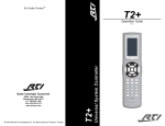
T2+ UNIVERSAL SYSTEM CONTROLLER
Device List
Tool Bar
Menu Bar
Touchscreen Grid
Page List
Design Window
Tool Palette
Library Browser
Frame Scrolling Buttons
Button Styles
Keypad Buttons
System Workspace Device List – Displays all
devices in a System File for easy selection.
Tool Palette – Icons for easy access to frequently
used design features.
Menu Bar – Provides drop down menus of all programming features.
Button Styles – Icons for fast editing of button
styles. Toolbar – Icons for easy access to frequently used
programming features.
Design Window – Displays the currently selected
device for editing. Page List – Displays the name and number of the
pages added to a device. Frame Scrolling Buttons – Provides access to
the multiple frames of a page.
Touchscreen Grid – Displays the page contents
of the LCD display for editing.
Keypad Buttons – Fixed buttons programmed
with frequently used control functions. Library Browser – Displays IR commands and
bitmaps for easy drag and drop programming.
13
TheaterTouch Designer
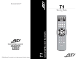
T1 UNIVERSAL SYSTEM CONTROLLER
Device List
Tool Bar
Menu Bar
Library Browser
Page List
Design Window
Tool Palette
Keypad Buttons
System Workspace Device List – Displays all
devices in a System File for easy selection.
Library Browser – Displays IR commands and
graphics for easy drag and drop programming.
Menu Bar – Provides drop down menus of all programming features.
Tool Palette – Icons for easy access to frequently
used design features.
Toolbar – Icons for easy access to frequently used
programming features.
Design Window – Displays the currently selected
device for editing. Page List – Displays the name and number of all
programmable pages. Keypad Buttons – Program these buttons to control the individual components in a system. 14
Chapter 2. Programming Overview
U1 UNIVERSAL SYSTEM CONTROLLER
Device List
Tool Bar
Menu Bar
Library Browser
Page List
Design Window
Tool Palette
Keypad Buttons
System Workspace Device List– Displays all
devices in a System File for easy selection.
Library Browser – Displays IR commands and
graphics for easy drag and drop programming.
Menu Bar – Provides drop down menus of all programming features.
Tool Palette – Icons for easy access to frequently
used design features.
Toolbar – Icons for easy access to frequently used
programming features.
Design Window – Displays the currently selected
device for editing. Page List – Displays the name and number of all
programmable pages. Keypad Buttons – Program these buttons to control the individual components in a system. 15
TheaterTouch Designer
RP-6/RP-1 SYSTEM CONTROL PROCESSOR
Device List
Tool Bar
Menu Bar
System Macro List
Device List – Displays all devices in a System File
for easy selection.
Toolbar – Icons for easy access to frequently used
programming features.
Menu Bar – Provides drop down menus of all programming features.
System Macro Window – A list of added system
macros displayed for editing (see Understanding
System Macros - Chapter 8 for more information).
16
Chapter 2. Programming Overview
DESIGN GUIDELINES
1. Be consistent with the location of similar buttons. For example, if you have a DVD player and a VCR in your
system, try to make the transport controls (Play, Pause, Stop, etc.) on both pages look similar.
2. It's not necessary to re-create each remote in its entirety. Think of the functions the user will be using daily.
3. Use macros to hide complex command sequences from the user. For example, instead of presenting the user
with a 0-9 key pad for changing channels on their TV, make a set of macros for CBS, HBO, etc. that send
the proper channel numbers automatically. The Channel Macro Wizard makes it easy to create this type of
macro.
4. (T2+ only) - Use bitmaps instead of custom buttons wherever possible. Bitmaps take half as much device
memory as custom buttons do, so you can put more of them in your device (See Custom Buttons and Bitmaps
- Chapter 6 for more information.)
GETTING HELP
TheaterTouch Designer includes an extensive on-line help system. If you need help with any tool or command,
select the What’s this? button on the Toolbar.
If you need an explanation of any item in a dialog box, select the Help button in the dialog’s title bar, and
then select the control you would like to learn about.
17
TheaterTouch Designer
Chapter 3. Working with System Files
INTRODUCTION TO SYSTEM FILES
Each file you create with TheaterTouch Designer is called a system file. A system file consists of a mixture of
control processors and remote control devices.
The System Workspace has a device list that displays an icon for each device stored in the system file. Click any
icon to open that device for editing.
Many portions of TheaterTouch Designer behave differently depending on whether or not a control processor is
present in the system file. If you do not add a control processor to your system, you can still have multiple remote
control devices in the system file but they function independently. Adding a control processor causes all remote
control devices in the system to use it by default, storing all commands and macros in the control processor
rather than the remote control device. You can use the Properties command on the Device menu to change this
behavior for each device.
CREATING A NEW FILE
1. Choose New from the File menu or select the New File icon on the Toolbar.
2. Specify the name and directory for the file when saving for the first time and choose Save.
The files created with TheaterTouch Designer hold all the elements that make up an individual remote file. They
have the extension .rti and may be stored in any directory.
Default directory is: [C:\Program Files\RTI\TheaterTouch Designer\My Systems]
18
Chapter 3. Working with System Files
OPENING AN EXISTING FILE
1. Choose Open from the File Menu or select the Open File icon from the Toolbar.
2. Select the file you wish to open.
3. Choose Open.
This command opens an existing system file. The currently open file, if any, will be closed. If you wish to open a
device in the current system, click on its icon in the System Workspace.
SAVING A FILE
1. Choose Save from the File Menu or select the Save File icon on the Toolbar.
2. Specify the name and directory for the file when saving for the first time and select Save.
19
TheaterTouch Designer
EDITING SYSTEM PROPERTIES
1. Choose System Properties from the File menu.
2. Select the tabs in the System Properties dialog box to edit the system properties that affect all devices.
ZONE SETTINGS
Setting unique System Zone Codes allows individual operation of
multiple RTI systems located within the same installation or systems
located in close proximity to each other (i.e. a close neighbor that
has a TheaterTouch System).
Note: Only adjust the Zone Code to keep separate RTI systems from
communicating with each another. Within a single RTI system file
each control processor is addressable by changing the output properties of a device or button.
1. Select the Zone tab and edit the System Zone Code.
2. Choose OK to confirm the new System Zone Code
DEALER INFORMATION
1. Select the Dealer Information tab and enter all pertinent dealer
data and installation notes.
2. Choose OK to confirm the new settings.
CLIENT INFORMATION
1. Select the Client Information tab and enter all .
pertinent client data and notes. 2. Choose OK to confirm the new settings.
20
Chapter 4. Working with Devices
Chapter 4. Working with Devices
INTRODUCTION TO DEVICES
Each TheaterTouch system file contains the devices that correspond to the actual control processors and remote
control devices included in a system. Add each device individually to match the control system you are programming. ADDING A DEVICE
1. Choose Add New from the Device menu or select the New
Device icon .
2. Select the icon of the type of device you wish to add.
3. Enter a name for the device and choose OK to confirm the
new name.
4. The new device appears in a Device list located in the system
workspace.
IMPORTING A DEVICE
This command copies a single device from another system file into the current one.
1. Choose Import Device from the Device menu.
2. Select the system file that contains the device to be imported.
3. Choose the device from a list of all devices in that system.
4. Choose OK to confirm the device.
21
TheaterTouch Designer
DELETING A DEVICE
1. Select the icon of the device you wish to delete from the Device List.
2. Choose Delete from the Device Menu or select the Delete Device icon .
3. Choose Yes to confirm deletion.
4. The device is removed from the system file.
RENAMING A DEVICE
1. Select the icon of the device you wish to rename from the Device List.
2. Choose Rename from the Device Menu.
3. Enter a new name for the device and choose OK to confirm the new name.
4. The device is displayed in the Device list with a new name.
22
Chapter 4. Working with Devices
DUPLICATING A DEVICE
1. Select the icon of the device you wish to duplicate from the Device List.
2. Choose Duplicate from the Device Menu.
3. Enter a new name for the device and choose OK to confirm the new name.
4. The duplicated device is displayed in the Device list with a new name.
CLOSING A DEVICE
This programming option closes the current device. This does not close the system file. If you wish to close the
system file, use the Close System command on the File menu.
1. Select Close from the Device menu.
2. The edit window for the selected device closes.
SAVING A DEVICE
Saving the currently selected device in the system:
1. Select a device from the device list.
2. Choose Save from the Device Menu or select the Save icon .
Saving all devices in the system:
1. Choose Save All Devices from the File Menu.
EDITING A DEVICE
1. Select the icon of the device you wish to edit from the Device List.
2. The Design Window appears for that device allowing you to perform edits.
23
TheaterTouch Designer
EDITING DEVICE PROPERTIES
1. Choose Properties from the Device menu to change settings that affect the currently selected Device.
2. Select each of the tabs in the Device Properties dialog box to edit the individual device properties.
Note: Many of these properties can be accessed directly on touchscreen remote devices through their respective Control Panels, however it should be noted that changes made locally on a remote will be over-written upon
programming it with the TheaterTouch Software.
K4 GENERAL TAB
IGNORE FIRST PRESS FROM POWER DOWN
MODE
1. Enabling this option causes the device to ignore the
first button press if the unit is powered down (the
backlight is off.) The first button press will wake up
the device and turn on the backlight, but will not activate any programmed command or macro.
ENABLE IR RECEIVER
2. Enabling this option allows signals received by the
built-in IR receiver to be passed through to the IR
output.
POWER DOWN TIME
3. Adjust the amount of time the unit stays awake after
the last button press of the touchscreen. The time is
variable from 1 second to 60 seconds (default is 10
seconds).
VIDEO INPUT STANDARD
4. Select the type of Video Input Standard that will be
used for all of the video feeds
NTSC = USA/Canada
PAL = Europe/Asia/Australia
5. Choose OK to confirm the new settings.
24
Chapter 4. Working with Devices
K4 BACKLIGHT TAB
ENABLE AMBIENT LIGHT SENSOR
1. Check this box to enable a built-in light sensor to
determine the current room lighting conditions and
change the backlight levels according to these conditions and the current activity status of the control
device.
BACKLIGHT LEVELS
2. Use these sliders to adjust the backlight setting for
normal lighting conditions and dark lighting conditions when the Ambient Light Sensor is enabled for
both Active and Idle status.
Active Status = Device is in use
Idle Status = Power Down Time has expired
(set on the "General" tab)
BACKLIGHT LEVEL (ACTIVE)
3. Use this slider to adjust the backlight setting for
when the Ambient Light Sensor is disabled and the
control device status is Active.
BACKLIGHT LEVEL (IDLE)
4. Use this slider to adjust the backlight setting for
when the Ambient Light Sensor is disabled and the
control device status is Idle.
5. Choose OK to confirm the new settings.
25
TheaterTouch Designer
K4 SOUNDS TAB
ENABLE BEEPER
1. Check this box to enable the beeper. If this box is
checked, the remote control will play the default button
beep sound every time a button is pressed.
VOLUME
2. Set the Volume slider to set volume level of the beeper.
DEFAULT BUTTON BEEP SOUND:
3. Determines the default sound for all buttons on the
control device. System beep is the built-in beep sound.
Choose from the available sounds in the drop down list
to change the device default.
AVAILABLE SOUNDS
Drop Down List of Available Sounds
4. Add to the list of Available Sounds by selecting Change.
An Open Sound File dialog box appears and allows you
to select a *.wav file.
- Remove a file from the list by selecting Remove.
- Test an added sound file by selecting Play
- The only limitation on sound length is the amount of
available memory on the remote device.
5. Choose OK to confirm the new settings.
Open Sound File Dialog Box
26
Chapter 4. Working with Devices
K4 NETWORK TAB
DHCP
1. Check this box to configure the device's network interface
using DHCP. You must have a DHCP server (such as a router
or cable/DSL modem) on the network for this to work. In
most cases, this is the option you should use.
MANUALLY CONFIGURE NETWORK SETTINGS
2. Use this selection to configure the device's network interface
using a static IP address. The values can be obtained by contacting your ISP or your network administrator.
- Enter the device's static IP Address
- Enter the network's:
Netmask
Gateway IP Address
DNS Server 1
DNS Server 2 (If only one is available, leave blank)
ALLOW THE DEVICE TO BE PROGRAMMED OVER THE NETWORK
3. Check this box to allow the device to be programmed remotely via the device's ethernet interface. If
you uncheck this box you will have to use a direct USB connection to update the device's programming.
Unchecking this box provides increased security by preventing the device's programming from being altered
over the network.
4. Select OK to confirm all selections.
27
TheaterTouch Designer
K4 WEB BROWSER TAB
HOME PAGE
1. Enter the URL for the default home page that the web browser will
navigate to.
USE PROXY SERVER
2. Check this box to enable the use of a web proxy server. In most
cases this option will not be used.
- Enter the host name or the IP address of the proxy server
- Enter the Port number used by the proxy server
ADJUST WEB PAGES TO REDUCE HORIZONTAL
SCROLLING
3. Check this box to enable the browser to automatically resize web
pages to fit on the screen. In most cases, this will reduce the amount
of scrolling needed to view the entire width of a web page, however
some websites will not appear correctly when this option is enabled.
4. Select OK to confirm all selections.
K4 CLOCK TAB
SET CLOCK FROM PC WHEN DOWNLOADING
1. Check this box to automatically synchronize the control device's
clock with the clock on your PC when you download the program
to the device. (Make sure the PC's clock is set correctly when
using this option.)
ENABLE NTP SYNCHRONIZATION
2. Check this box to enable automatic clock setting via the Network
Time Protocol. Enabling NTP requires either an NTP server on your
local network or access to an NTP server on the internet.
3. Enter the address of the NTP server you would like to use. If you
have constant internet access, you can use the default value. If not,
input the address of an NTP server on the local network.
TIME ZONE
4. Choose the time zone for the location that the device will be installed in. This setting must be set correctly
for NTP and automatic Daylight Saving Time adjustment to function correctly.
AUTOMATICALLY ADJUST FOR DAYLIGHT SAVING TIME
5. Check this box to enable automatic Daylight Saving Time adjustment. (Make sure the time zone is set correctly when using this option.)
6. Select OK to confirm all selections.
NOTE: To insert the time onto a K4 control device
page, create a button, right click and go to the Edit
Text option, then choose the Control Variable button
select the time format to be displayed on the button.
28
Chapter 4. Working with Devices
K4 OUTPUT TAB
DEFAULT OUTPUT MODE
1. Change the default output mode by selecting one of the two
available options listed.
Note: To have any single button on the device operate in a
different output mode or trigger a different control processor
from the device default, you must edit the Button Properties
Output Tab (See Output Tab - Chapter 6 for more information
on editing a buttons properties).
STANDALONE
In-wall control devices are set to the Standalone output
mode by default when a control processor is not included
in a system file. In this mode, devices output IR commands
and issue macros to components directly.
IR TRIGGER CODES FOR CONTROL SYSTEM
In-wall control devices are set to the IR Trigger Codes for
Control System output mode by default when a control
processor is included in a system file. In this mode,
devices send IR trigger codes to the control processor
which outputs IR commands and macros, and also provides access to additional features such as RS-232 commands, IR routing, power sensing and relay control.
2. Choose which control processor a device triggers by default (all control processors included in the system file are
displayed for selection in the drop down list.)
3. Adjust the IR Trigger Code carrier frequency to improve IR trigger code reliability when using an IR receiver and
a control processor.
4. Choose OK to confirm the new settings.
29
TheaterTouch Designer
K4 FLAG NAMES TAB
1. Input the names of the flags to be associated with this device in a
Flag Macro Step. Note: Flags are used in macros to keep track of a component
or remote device's status and act based on that status. For
example, you can use this functionality to make discrete power
ON and OFF macros for components for which you have only
toggle codes. Flags exist on a per-device basis, therefore you
must name each flag used by each remote device or contol processor. (See Working with Macros - Chapter 8 for more information on programming macros using Flags).
2. Choose OK to confirm the new settings.
K4 NOTES TAB
1. Enter any device specific notes for future reference. Note: This field does not affect the functionality of the device, it is
for your informational purposes only.
2. Choose OK to confirm the new settings.
30
Chapter 4. Working with Devices
RK3 GENERAL TAB)
IGNORE FIRST PRESS FROM POWER DOWN MODE
1. Enabling this option causes the device to ignore the first button press if the unit is powered down (the backlight is off.) The first button press will wake up the device and turn on the backlight, but will not activate any
programmed command or macro.
ENABLE IR RECEIVER
2. Enabling this option allows signals received by the built-in IR receiver to be passed through to the IR
output.
POWER DOWN TIME
3. Adjust the amount of time the unit stays awake after the last button press of the touchscreen. The time
is variable from 1 second to 60 seconds (default is 10 seconds).
4. Choose OK to confirm the new settings.
31
TheaterTouch Designer
RK3 BACKLIGHT TAB
ENABLE AMBIENT LIGHT SENSOR
1. Check this box to enable a built-in light sensor to
determine the current room lighting conditions and
change the backlight levels according to these conditions and the current activity status of the control
device.
BACKLIGHT LEVELS
2. Use these sliders to adjust the backlight setting for
normal lighting conditions and dark lighting conditions when the Ambient Light Sensor is enabled for
both Active and Idle status.
Active Status = Device is in use
Idle Status = Power Down Time has expired
(set on the "General" tab)
BACKLIGHT LEVEL (ACTIVE)
3. Use this slider to adjust the backlight setting for
when the Ambient Light Sensor is disabled and the
control device status is Active.
BACKLIGHT LEVEL (IDLE)
3. Use this slider to adjust the backlight setting for
when the Ambient Light Sensor is disabled and the
control device status is Idle.
4. Choose OK to confirm the new settings.
32
Chapter 4. Working with Devices
RK3 SOUNDS TAB
ENABLE BEEPER
1. Check this box to enable the beeper. If this box is
checked, the remote control will play the default button
beep sound every time a button is pressed.
VOLUME
2. Set the Volume slider to set volume level of the beeper.
DEFAULT BUTTON BEEP SOUND:
3. Determines the default sound for all buttons on the
control device. System beep is the built-in beep sound.
Choose from the available sounds in the drop down list
to change the device default.
AVAILABLE SOUNDS
Drop Down List of Available Sounds
4. Add to the list of Available Sounds by selecting Change.
An Open Sound File dialog box appears and allows you
to select a *.wav file.
- Remove a file from the list by selecting Remove.
- Test an added sound file by selecting Play
- The only limitation on sound length is the amount of
available memory on the remote device.
Open Sound File Dialog Box
33
TheaterTouch Designer
RK3 NETWORK TAB
DHCP
1. Check this box to configure the device's network interface
using DHCP. You must have a DHCP server (such as a router
or cable/DSL modem) on the network for this to work. In
most cases, this is the option you should use.
MANUALLY CONFIGURE NETWORK SETTINGS
2. Use this selection to configure the device's network interface
using a static IP address. The values can be obtained by contacting your ISP or your network administrator.
- Enter the device's static IP Address
- Enter the network's:
Netmask
Gateway IP Address
DNS Server 1
DNS Server 2 (If only one is available, leave blank)
ALLOW THE DEVICE TO BE PROGRAMMED OVER THE NETWORK
3. Check this box to allow the device to be programmed remotely via the device's ethernet interface. If
you uncheck this box you will have to use a direct USB connection to update the device's programming.
Unchecking this box provides increased security by preventing the device's programming from being altered
over the network.
4. Select OK to confirm all selections.
34
Chapter 4. Working with Devices
RK3 WEB BROWSER TAB
HOME PAGE
1. Enter the URL for the default home page that the web browser will
navigate to.
USE PROXY SERVER
2. Check this box to enable the use of a web proxy server. In most
cases this option will not be used.
- Enter the host name or the IP address of the proxy server
- Enter the Port number used by the proxy server
ADJUST WEB PAGES TO REDUCE HORIZONTAL
SCROLLING
3. Check this box to enable the browser to automatically resize web
pages to fit on the screen. In most cases, this will reduce the amount
of scrolling needed to view the entire width of a web page, however
some websites will not appear correctly when this option is enabled.
4. Select OK to confirm all selections.
RK3 CLOCK TAB
SET CLOCK FROM PC WHEN DOWNLOADING
1. Check this box to automatically synchronize the control device's
clock with the clock on your PC when you download the program
to the device. (Make sure the PC's clock is set correctly when
using this option.)
ENABLE NTP SYNCHRONIZATION
2. Check this box to enable automatic clock setting via the Network
Time Protocol. Enabling NTP requires either an NTP server on your
local network or access to an NTP server on the internet.
3. Enter the address of the NTP server you would like to use. If you
have constant internet access, you can use the default value. If not,
input the address of an NTP server on the local network.
TIME ZONE
4. Choose the time zone for the location that the device will be
installed in. This setting must be set correctly for NTP and automatic Daylight Saving Time adjustment to
function correctly.
AUTOMATICALLY ADJUST FOR DAYLIGHT SAVING TIME
5. Check this box to enable automatic Daylight Saving Time adjustment. (Make sure the time zone is set correctly when using this option.)
6. Select OK to confirm all selections.
NOTE: To insert the time onto an RK3 page, create a
button, right click and go to the Edit Text option, then
choose the Control Variable button select the time
format to be displayed on the button.
35
TheaterTouch Designer
RK3 OUTPUT TAB
DEFAULT OUTPUT MODE
1. Change the default output mode by selecting one of the
two available options listed.
Note: To have any single button on the device operate in
a different output mode or trigger a different control processor from the device default, you must edit the Button
Properties Output Tab (See Output Tab - Chapter 6 for
more information on editing a buttons properties).
STANDALONE
In-wall control devices are set to the Standalone output
mode by default when a control processor is not included in a system file. In this mode, devices output IR
commands and issue macros to components directly.
IR TRIGGER CODES FOR CONTROL
SYSTEM
In-wall control devices are set to the IR Trigger Codes
for Control System output mode by default when a
control processor is included in a system file. In this
mode, devices send IR trigger codes to the control
processor which outputs IR commands and macros,
and also provides access to additional features such
as RS-232 commands, IR routing, power sensing and
relay control.
2. Choose which control processor a device triggers by default (all control processors included in the system file are
displayed for selection in the drop down list.)
3. Adjust the IR Trigger Code carrier frequency to improve IR trigger code reliability when using an IR receiver and
a control processor.
4. Choose OK to confirm the new settings.
36
Chapter 4. Working with Devices
RK3 GLOBAL KEYS TAB
The command programming for Global keys is common to
every page of a remote control device.
1. Switch a key from unique to Global by choosing the Global
Keys tab in the Device Properties dialog or by clicking the
right mouse button on the key and choosing "Make This Key
Global".
2. Place a check mark next to all Global keys.
3. Select OK to confirm all selections.
Important Note: Using the Global Keys tab does not preserve
previously programmed commands. Use the right button context menu of a selected button and select “Make this Key Global”
to designate the command on that button and that page to be
the global command. RK3 POWER LED TAB
The Power LED color can be set depending on the status of the
built in Power Status Inputs and Relays or by using Led Control
macro steps.
1. Choose how the Power LED color will be determined.
OWER STATUS INPUT
P
Onlythe voltage present on the PWR STATUS input will
determine the color.
RELAY OUTPUT
Onlythe current setting of the RELAY CTRL output will
determine the color.
BOTH
Boththe voltage present on the PWR STATUS input and the
current setting of the RELAY CTRL output will determine the
color.
NEITHER
LEDControl steps within macros will determine the color. \
2. Choose OK to confirm the new settings.
37
TheaterTouch Designer
RK3 FLAG NAMES TAB
1. Input the names of the flags to be associated with this device in a
Flag Macro Step. Note: Flags are used in macros to keep track of a component
or remote device's status and act based on that status. For
example, you can use this functionality to make discrete power
ON and OFF macros for components for which you have only
toggle codes. Flags exist on a per-device basis, therefore you
must name each flag used by each remote device or contol processor. (See Working with Macros - Chapter 8 for more information on programming macros using Flags).
2. Choose OK to confirm the new settings.
RK3 NOTES TAB
1. Enter any device specific notes for future reference. Note: This field does not affect the functionality of the device, it is
for your informational purposes only.
2. Choose OK to confirm the new settings.
38
Chapter 4. Working with Devices
T4 GENERAL TAB
ENABLE TILT SWITCH
1. Enabling the Tilt Switch allows the internal tilt switch to turn on the display and button backlight when the
remote control is handled. This option is enabled by default.
DISABLE KEYPAD BACKLIGHTS
2. Check this box to turn off the backlight on the hard buttons.
IGNORE FIRST PRESS FROM POWER DOWN MODE
3. Enabling this option causes the device to ignore the first button press if the unit is powered down (the backlight is off.) The first button press will wake up the device and turn on the backlight, but will not activate any
programmed command or macro.
POWER DOWN TIME
4. Adjust the amount of time the unit stays awake after the last button press of the touchscreen. The time
is variable from 1 second to 60 seconds (default is 10 seconds).
VIDEO INPUT STANDARD
5. Select the type of Video Input Standard that will be used for all of the video feeds
NTSC = USA/Canada
PAL = Europe/Asia/Australia
LOW BATTERY WARNING TIME
6. Set the low battery warning time to determine
when the low battery icon appears on the LCD
screen. Choose one of the three available times,
Normal (default time), Short or Long.
IR OUTPUT DESTINATION
7. Select how infrared codes should be delivered from
the T4
Internal LED - sends IR directly from the T4
Hardwire (Requires EM4) - IR is sent hardwired through the EM4 expansion module
8. Choose OK to confirm the new settings.
39
TheaterTouch Designer
T4 BACKLIGHT TAB
ENABLE AMBIENT LIGHT SENSOR
1. Check this box to enable a built-in light sensor to
determine the current room lighting conditions and
change the backlight levels according to these conditions and the current activity status of the control
device.
BACKLIGHT LEVELS
2. Use these sliders to adjust the backlight setting for
normal lighting conditions and dark lighting conditions when the Ambient Light Sensor is enabled for
both Active and Idle status.
Active Status = Device is in use
Idle Status = Power Down Time has expired
(set on the "General" tab)
BACKLIGHT LEVEL (ACTIVE)
3. Use this slider to adjust the backlight setting for
when the Ambient Light Sensor is disabled and the
control device status is Active.
BACKLIGHT LEVEL (IDLE)
4. Use this slider to adjust the backlight setting for
when the Ambient Light Sensor is disabled and the
control device status is Idle.
5. Choose OK to confirm the new settings.
40
Chapter 4. Working with Devices
T4 SOUNDS TAB
ENABLE BEEPER
1. Check this box to enable the beeper. If this box is
checked, the remote control will play the default button
beep sound every time a button is pressed.
VOLUME
2. Set the Volume slider to set volume level of the beeper.
DEFAULT BUTTON BEEP SOUND:
3. Determines the default sound for all buttons on the
control device. System beep is the built-in beep sound.
Choose from the available sounds in the drop down list
to change the device default.
AVAILABLE SOUNDS
Drop Down List of Available Sounds
4. Add to the list of Available Sounds by selecting Change.
An Open Sound File dialog box appears and allows you
to select a *.wav file.
- Remove a file from the list by selecting Remove.
- Test an added sound file by selecting Play
- The only limitation on sound length is the amount of
available memory on the remote device.
5. Choose OK to confirm the new settings.
Open Sound File Dialog Box
41
TheaterTouch Designer
T4 WEB BROWSER TAB
HOME PAGE
1. Enter the URL for the default home page that the web browser will
navigate to.
USE PROXY SERVER
2. Check this box to enable the use of a web proxy server. In most
cases this option will not be used.
- Enter the host name or the IP address of the proxy server
- Enter the Port number used by the proxy server
ADJUST WEB PAGES TO REDUCE HORIZONTAL
SCROLLING
3. Check this box to enable the browser to automatically resize web
pages to fit on the screen. In most cases, this will reduce the amount
of scrolling needed to view the entire width of a web page, however
some websites will not appear correctly when this option is enabled.
4. Select OK to confirm all selections.
T4 CLOCK TAB
SET CLOCK FROM PC WHEN DOWNLOADING
1. Check this box to automatically synchronize the control device's
clock with the clock on your PC when you download the program
to the device. (Make sure the PC's clock is set correctly when
using this option.)
ENABLE NTP SYNCHRONIZATION
2. Check this box to enable automatic clock setting via the Network
Time Protocol. Enabling NTP requires either an NTP server on your
local network or access to an NTP server on the internet.
3. Enter the address of the NTP server you would like to use. If you
have constant internet access, you can use the default value. If not,
input the address of an NTP server on the local network.
TIME ZONE
4. Choose the time zone for the location that the device will be installed in. This setting must be set correctly
for NTP and automatic Daylight Saving Time adjustment to function correctly.
AUTOMATICALLY ADJUST FOR DAYLIGHT SAVING TIME
5. Check this box to enable automatic Daylight Saving Time adjustment. (Make sure the time zone is set correctly when using this option.)
6. Select OK to confirm all selections.
NOTE: To insert the time onto a T4 control device
page, create a button, right click and go to the Edit
Text option, then choose the Control Variable button
select the time format to be displayed on the button.
42
Chapter 4. Working with Devices
T4 OUTPUT TAB
DEFAULT OUTPUT MODE
1. Change the default output mode by selecting one of the two
available options listed.
Note: To have any single button on the device operate in a
different output mode or trigger a different control processor
from the device default, you must edit the Button Properties
Output Tab (See Output Tab - Chapter 6 for more information
on editing a buttons properties).
STANDALONE
In-wall control devices are set to the Standalone output
mode by default when a control processor is not included
in a system file. In this mode, devices output IR commands
and issue macros to components directly.
IR TRIGGER CODES FOR CONTROL SYSTEM
In-wall control devices are set to the IR Trigger Codes for
Control System output mode by default when a control
processor is included in a system file. In this mode,
devices send IR trigger codes to the control processor
which outputs IR commands and macros, and also provides access to additional features such as RS-232 commands, IR routing, power sensing and relay control.
2. Choose which control processor a device triggers by default (all control processors included in the system file are
displayed for selection in the drop down list.)
3. Adjust the IR Trigger Code carrier frequency to improve IR trigger code reliability when using an IR receiver and
a control processor.
4. Choose OK to confirm the new settings.
43
TheaterTouch Designer
T4 NETWORK TAB
Use the Network(100BaseT) tab for hardwired Ethernet when using the EM4 Expansion
Module. Use the Network(WiFi) tab to use the built in wireless networking adapter for
wireless Ethernet.
DHCP
1. Check this box to configure the device's network interface using DHCP.
You must have a DHCP server (such as a router or cable/DSL modem)
on the network for this to work. In most cases, this is the option you
should use.
MANUALLY CONFIGURE NETWORK SETTINGS
2. Use this selection to configure the device's network interface using a
static IP address. The values can be obtained by contacting your ISP or
your network administrator.
- Enter the device's static IP Address
- Enter the network's:
Netmask
Gateway IP Address
DNS Server 1
DNS Server 2 (If only one is available, leave blank)
ALLOW THE DEVICE TO BE PROGRAMMED OVER THE NETWORK
3. Check this box to allow the device to be programmed remotely via the device's ethernet interface. If
you uncheck this box you will have to use a direct USB connection to update the device's programming.
Unchecking this box provides increased security by preventing the device's programming from being altered
over the network.
4. Select OK to confirm all selections.
44
Chapter 4. Working with Devices
T4 WIRELESS TAB
Use the Network(WiFi) tab to configure the built-in wireless networking adapter for
wireless Ethernet.
ENABLE WIRELESS NETWORK ADAPTER (802.11b)
1. Check this box to use the built-in wireless networking adapter for wireless Ethernet.
ENABLE WIRELESS LAN STATUS LED
2. Check this box to enable the LED which will display the connection status to a wireless network.
WIRELESS NETWORKING CONFIGURATION
3. Use these buttons to add wireless networking configurations.
- Add - Click this button to enter a wireless network's configuration.
- Delete - Click this button to delete a wireless network configuration.
- Edit - Click this button to edit a wireless network's configuration.
- Move Up - Click this button to move a wireless network up in the connection priority list.
- Move Down - Click this button to move a wireless network down in the connection priority list.
NAME (SSID)
4. Enter the name of the wireless network.
AUTHENTICATION
5. Select the authentication type of the wireless network.
Choose from - Open, Shared Key or WPA-PSK
ENCRYPTION)
6. Select if the WEP encryption is being used when using
Open or Shared Key Authentication, or TKIP encryption when
WPA-PSK is being used.
KEY
4. Enter the wireless network encryption key.
5. Select OK to confirm all selections.
45
TheaterTouch Designer
T4 FLAG NAMES TAB
1. Input the names of the flags to be associated with this device in a
Flag Macro Step. Note: Flags are used in macros to keep track of a component or remote device's status and act based on that status. For example, you can use this functionality to make discrete
power ON and OFF macros for components for which you
have only toggle codes. Flags exist on a per-device basis,
therefore you must name each flag used by each remote
device or contol processor. (See Working with Macros Chapter 8 for more information on programming macros using
Flags).
2. Choose OK to confirm the new settings.
T4 NOTES TAB
1. Enter any device specific notes for future reference. Note: This field does not affect the functionality of the device, it
is for your informational purposes only.
2. Choose OK to confirm the new settings.
46
Chapter 4. Working with Devices
T3 GENERAL TAB
ENABLE TILT SWITCH
1. Enabling the Tilt Switch allows the internal tilt switch to turn on the display and button backlight when the
remote control is handled. This option is enabled by default.
POWER DOWN TIME
2. Adjust the amount of time the unit stays awake after the remote is set down after use. The time is variable from 1 second to 60 seconds (default is 10 seconds). During sleep mode, the remote control uses
virtually no battery power.
LOW BATTERY WARNING TIME
3. Set the low battery warning time to determine when the low battery icon appears on the LCD screen.
Choose one of the three available times, Normal (default time), Short or Long.
4. Choose OK to confirm the new settings.
47
TheaterTouch Designer
T3 BACKLIGHT TAB
ENABLE AMBIENT LIGHT SENSOR
1. Check this box to enable a built-in light sensor to provide
one of two different backlight levels depending on the current room lighting conditions. This option is enabled by
default.
BACKLIGHT LEVELS
2. Use these sliders to adjust the backlight setting for normal
lighting conditions and dark lighting conditions when the
Ambient Light Sensor is enabled.
BACKLIGHT LEVEL
3. Use this slider to adjust the backlight setting for all conditions when the Ambient Light Sensor is disabled.
4. Choose OK to confirm the new settings.
48
Chapter 4. Working with Devices
T3 SOUNDS TAB
ENABLE BEEPER
1. Check this box to enable the beeper. If this box is
checked, the remote control will play the default button
beep sound every time a button is pressed.
VOLUME
2. Set the Volume slider to set volume level of the beeper.
DEFAULT BUTTON BEEP SOUND:
3. Determines the default sound for all buttons on the
control device. System beep is the built-in beep sound.
Choose from the available sounds in the drop down list
to change the device default.
AVAILABLE SOUNDS
Drop Down List of Available Sounds
4. Add to the list of Available Sounds by selecting Change.
An Open Sound File dialog box appears and allows you
to select a *.wav file.
- Remove a file from the list by selecting Remove.
- Test an added sound file by selecting Play
- The only limitation on sound length is the amount of
available memory on the remote device.
Open Sound File Dialog Box
49
TheaterTouch Designer
T3 OUTPUT TAB
DEFAULT OUTPUT MODE
1. Change the default output mode by selecting one of the three
available options listed on the Device Properties Output Tab.
Note: To have any single button on the remote control
device operate in a different output mode or trigger a different
control processor from the device default, you must edit the
Button Properties Output Tab (See Output Tab - Chapter 6 for
more information on editing a buttons properties).
STANDALONE
AnyIR commands that you assign to buttons will be output
directly by the infrared output on the remote device, and the
device will process any macros attached to buttons. Actions
that require a control processor will need to be created on the
control processor in a System Macro and added to a macro
attached to a button. (See Understanding System Macros
- Chapter 8 for more information on System Macros.)
RF TRIGGER CODES FOR CONTROL SYSTEM
In this mode, all commands and macros that you assign to buttons will be stored in the control processor
instead of the device. Each button on the device will send an RF "trigger" code to the control processor that
tells it which command and/or macro to process. Note: In this mode, macros are also much more reliable. There is only a single "trigger" code sent from the
device to the control processor to start the macro, after which the control processor will run the entire macro
to completion. However, since the macros are not running on the remote control device, it is not possible for
the macro to affect the remote control in any way, such as changing pages or making sounds. To make these
functions possible refer to the instructions for Standalone output mode above.
IR TRIGGER CODES FOR CONTROL SYSTEM
This mode is identical to the "RF Trigger Codes for Control System" mode, except that an IR code is used to trigger the control processor instead of an RF code. (See Generate IR Trigger Codes for System Macros - Chapter
8 for information on obtaining IR trigger codes to be programmed into third-party devices.)
Note: Commands and macros are stored in the control processor in this mode, and all of the notes regarding macro processing in the RF Trigger Codes section apply.
2. Choose which control processor a remote control device triggers by default (all control processors included in the
system file are displayed for selection in the drop down list.)
3. Adjust the IR Trigger Code carrier frequency to improve IR trigger code reliability when using an IR receiver and a
control processor (this adjustment may be required only if a component controlled by the control processor is in
direct line of sight with the IR output of the interface device.)
4. Choose OK to confirm the new settings.
50
Chapter 4. Working with Devices
T3 GLOBAL KEYS TAB
The command programming for Global keys is common to
every page of an remote control device.
1. Switch a key from unique to Global by choosing the Global
Keys tab in the Device Properties dialog or by clicking the
right mouse button on the key and choosing "Make This Key
Global".
2. Place a check mark next to all Global keys.
3. Select OK to confirm all selections.
Important Note: Using the Global Keys tab does not preserve
previously programmed commands. Use the right button context menu of a selected button and select “Make this Key Global”
to designate the command on that button and that page to be
the global command. 51
TheaterTouch Designer
T3 FLAG NAMES TAB
1. Input the names of the flags to be associated with this device in
a Flag Macro Step. Note: Flags are used in macros to keep track of a component or remote device's status and act based on that status. For example, you can use this functionality to make discrete
power ON and OFF macros for components for which you
have only toggle codes. Flags exist on a per-device basis,
therefore you must name each flag used by each remote
device or contol processor. (See Working with Macros Chapter 8 for more information on programming macros using
Flags).
2. Choose OK to confirm the new settings.
T3 NOTES TAB
1. Enter any device specific notes for future reference. Note: This field does not affect the functionality of the device, it
is for your informational purposes only.
2. Choose OK to confirm the new settings.
52
Chapter 4. Working with Devices
T2+ GENERAL TAB
ENABLE BEEPER
1. Check this box to enable the beeper. If this box is
checked, the remote control will beep every time a button is pressed. This option is enabled by default.
ENABLE TILT SWITCH
2. Enabling the Tilt Switch allows the internal tilt switch
to turn on the display and button backlight when the
remote control is handled. This option is enabled by
default.
POWER DOWN TIME
3. Adjust the amount of time the unit stays awake after
the remote is set down after use. The time is variable
from 1 second to 60 seconds (default is 10 seconds).
During sleep mode, the remote control uses virtually
no battery power. BACKLIGHT
4. Choose one of the two backlighting options, on when
device is active or only on when the backlight keys is
pressed.
FRAME SCROLLING RATE
5. Slide this control to set how fast the frames scroll left and right when the frame scroll arrows are pressed. FRAME SCROLLING WRAPS AROUND EDGES
5. Select the frame scrolling wraps around at edges check box and the page frames will cycle back to the first
or last frame when using the frame right and left arrows.
SECURITY
6. Passcode: (default is 0000) Allows you to set the passcode that the Clear All function on the remote's control panel page as well as the Secured Button Option function that is available on all buttons.
7. Choose OK to confirm the new settings.
53
TheaterTouch Designer
T2+ OUTPUT TAB
DEFAULT OUTPUT MODE
1. Change the default output mode by selecting one of the three
available options listed on the Device Properties Output Tab.
Note: To have any single button on the remote control
device operate in a different output mode or trigger a different
control processor from the device default, you must edit the
Button Properties Output Tab (See Output Tab - Chapter 6 for
more information on editing a buttons properties).
STANDALONE
AnyIR commands that you assign to buttons will be output
directly by the infrared output on the remote device, and the
device will process any macros attached to buttons. Actions
that require a control processor will need to be created on the
control processor in a System Macro and added to a macro
attached to a button. (See Understanding System Macros
- Chapter 8 for more information on System Macros.)
RF TRIGGER CODES FOR CONTROL SYSTEM
In this mode, all commands and macros that you assign to
buttons will be stored in the control processor instead of the device. Each button on the device will send an
RF "trigger" code to the control processor that tells it which command and/or macro to process. Note: In this mode, macros are also much more reliable. There is only a single "trigger" code sent from the
device to the control processor to start the macro, after which the control processor will run the entire macro
to completion. However, since the macros are not running on the remote control device, it is not possible for
the macro to affect the remote control in any way, such as changing pages or making sounds. To make these
functions possible refer to the instructions for Standalone output mode above.
IR TRIGGER CODES FOR CONTROL SYSTEM
This mode is identical to the "RF Trigger Codes for Control System" mode, except that an IR code is used to trigger the control processor instead of an RF code. (See Generate IR Trigger Codes for System Macros - Chapter
8 for information on obtaining IR trigger codes to be programmed into third-party devices.)
Note: Commands and macros are stored in the control processor in this mode, and all of the notes regarding macro processing in the RF Trigger Codes section apply.
2. Choose which control processor a remote control device triggers by default (all control processors included in the
system file are displayed for selection in the drop down list.)
3. Adjust the IR Trigger Code carrier frequency to improve IR trigger code reliability when using an IR receiver and a
control processor (this adjustment may be required only if a component controlled by the control processor is in
direct line of sight with the IR output of the interface device.)
4. Choose OK to confirm the new settings.
54
Chapter 4. Working with Devices
T2+ GLOBAL KEYS TAB
The command programming for Global keys is common
to every page of a remote control device.
1. Switch a key from unique to Global by choosing the
Global Keys tab in the Device Properties dialog or
by clicking the right mouse button on the key and
choosing "Make This Key Global".
2. Place a check mark next to all Global keys.
3. Select OK to confirm all selections.
Important Note: Using the Global Keys tab does not
preserve previously programmed commands. Use the
right button context menu of a selected button and select
“Make this Key Global” to designate the command on that
button and that page to be the global command. 55
TheaterTouch Designer
T2+ FLAG NAMES TAB
1. Input the names of the flags to be associated with this device in a
Flag Macro Step. Note: Flags are used in macros to keep track of a component
or remote device's status and act based on that status. For
example, you can use this functionality to make discrete power
ON and OFF macros for components for which you have only
toggle codes. Flags exist on a per-device basis, therefore you
must name each flag used by each remote device or contol
processor. (See Working with Macros - Chapter 8 for more
information on programming macros using Flags).
2. Choose OK to confirm the new settings.
T2+ NOTES TAB
1. Enter any device specific notes for future reference. Note: This field does not affect the functionality of the device, it
is for your informational purposes only.
2. Choose OK to confirm the new settings.
56
Chapter 4. Working with Devices
T1 GENERAL TAB
ENABLE TILT SWITCH
1. Enabling the Tilt Switch allows the internal tilt
switch to turn on the button backlight when
the remote control is handled. This option is
enabled by default.
POWER DOWN TIME
2. Adjust the amount of time the unit stays awake
after the remote is set down after use. The
time is variable from 1 second to 60 seconds
(default is 10 seconds). During sleep mode, the
device uses virtually no battery power.
BACKLIGHT
3. Choose one of the two backlighting options, on
when the remote is active or only on when the
backlight key is pressed.
4. Choose OK to confirm the new settings.
57
TheaterTouch Designer
T1 OUTPUT TAB
DEFAULT OUTPUT MODE
1. Change the default output mode by selecting one of the three
available options listed on the Device Properties Output
Tab.
Note: To have any single button on the remote control
device operate in a different output mode or trigger a different control processor from the device default, you must edit
the Button Properties Output Tab (See Output Tab - Chapter
6 for more information on editing a buttons properties).
STANDALONE
AnyIR commands that you assign to buttons will be output
directly by the infrared output on the remote device, and the
device will process any macros attached to buttons. Actions
that require a control processor will need to be created on the
control processor in a System Macro and added to a macro
attached to a button. (See Understanding System Macros
- Chapter 8 for more information on System Macros.)
F TRIGGER CODES FOR CONTROL SYSTEM
R
In this mode, all commands and macros that you assign to buttons will be stored in the control processor
instead of the device. Each button on the device will send an RF "trigger" code to the control processor that
tells it which command and/or macro to process. Note: In this mode, macros are also much more reliable. There is only a single "trigger" code sent from the
device to the control processor to start the macro, after which the control processor will run the entire macro
to completion. However, since the macros are not running on the remote control device, it is not possible for
the macro to affect the remote control in any way, such as changing pages or making sounds. To make these
functions possible refer to the instructions for Standalone output mode above.
IR TRIGGER CODES FOR CONTROL SYSTEM
This mode is identical to the "RF Trigger Codes for Control System" mode, except that an IR code is used to trigger the control processor instead of an RF code. (See Generate IR Trigger Codes for System Macros - Chapter
8 for information on obtaining IR trigger codes to be programmed into third-party devices.)
Note: Commands and macros are stored in the control processor in this mode, and all of the notes regarding macro processing in the RF Trigger Codes section apply.
2. Choose which control processor a remote control device triggers by default (all control processors included in the
system file are displayed for selection in the drop down list.)
3. Adjust the IR Trigger Code carrier frequency to improve IR trigger code reliability when using an IR receiver and a
control processor (this adjustment may be required only if a component controlled by the control processor is in
direct line of sight with the IR output of the interface device.)
4. Choose OK to confirm the new settings.
58
Chapter 4. Working with Devices
T1 KEY LABELS TAB
1. Choose a Label for each of the available source keys. The
labels in the pull-down list correspond to the key cap set included with the device.
2. Choose a Label for the Extra Keys section to match the key
caps you have assigned to the blank spaces on the keypad.
3. Select OK to confirm the labels.
T1 GLOBAL TAB
The command programming for Global keys is common to
every page of a remote control device.
1. Switch a key from unique to Global by choosing the Global
Keys tab in the Device Properties dialog or by clicking the
right mouse button on the key and choosing "Make This Key
Global".
2. Place a check mark next to all Global keys.
3. Select OK to confirm all selections.
Important Note: Using the Global Keys tab does not preserve
previously programmed commands. Use the right button context
menu of a selected button and select “Make this Key Global” to
designate the command on that button and that page to be the
global command. 59
TheaterTouch Designer
T1 FLAG NAMES TAB
1. Input the names of the flags to be associated with this device in
a Flag Macro Step. Note: Flags are used in macros to keep track of a component or remote device's status and act based on that status. For example, you can use this functionality to make discrete
power ON and OFF macros for components for which you
have only toggle codes. Flags exist on a per-device basis,
therefore you must name each flag used by each remote
device or contol processor. (See Working with Macros Chapter 8 for more information on programming macros using
Flags).
2. Choose OK to confirm the new settings.
T1 NOTES TAB
1. Enter any device specific notes for future reference. Note: This field does not affect the functionality of the device, it
is for your informational purposes only.
2. Choose OK to confirm the new settings.
60
Chapter 4. Working with Devices
U1 OUTPUT TAB
DEFAULT OUTPUT MODE
1. Change the default output mode by selecting one of the two available
options listed on the Device Properties Output Tab.
Note: To have any single button on the remote control device operate in a different output mode or trigger a different control processor
from the device default, you must edit the Button Properties Output
Tab (See Output Tab - Chapter 6 for more information on editing a
buttons properties).
STANDALONE
Sincethe U1 cannot send IR commands, the Standalone mode is
only used when the Button Test Macro Step is used. In this case,
System Macros are set up on the Control Processor and are triggered by the remote device based upon the result of the Button
Test (Double Clicked, Held down or Tapped). (See Understanding
System Macros - Chapter 8 for more information on System
Macros.)
RF TRIGGER CODES FOR CONTROL SYSTEM
In this mode, all commands and macros that you assign to buttons will be stored in the control processor
instead of the device. Each button on the device will send an RF "trigger" code to the control processor that
tells it which command and/or macro to process. Note: In this mode, macros are also much more reliable. There is only a single "trigger" code sent from the
device to the control processor to start the macro, after which the control processor will run the entire macro
to completion. However, since the macros are not running on the remote control device, it is not possible for
the macro to affect the remote control in any way, such as changing pages or making sounds. To make these
functions possible refer to the instructions for Standalone output mode above.
2. Choose which control processor a remote control device triggers by default (all control processors included in the
system file are displayed for selection in the drop down list.)
3. Choose OK to confirm the new settings.
61
TheaterTouch Designer
U1 GLOBAL TAB
The command programming for Global keys is common to every page
of a remote control device.
1. Switch a key from unique to Global by choosing the Global Keys
tab in the Device Properties dialog or by clicking the right mouse
button on the key and choosing "Make This Key Global".
2. Place a check mark next to all Global keys.
3. Select OK to confirm all selections.
Important Note: Using the Global Keys tab does not preserve previously programmed commands. Use the right button context menu of
a selected button and select “Make this Key Global” to designate the
command on that button and that page to be the global command. U1 FLAG NAMES TAB
1. Input the names of the flags to be associated with this device in a Flag
Macro Step. Note: Flags are used in macros to keep track of a component or
remote device's status and act based on that status. For example,
you can use this functionality to make discrete power ON and OFF
macros for components for which you have only toggle codes. Flags exist on a per-device basis, therefore you must name each
flag used by each remote device or contol processor. (See Working
with Macros - Chapter 8 for more information on programming macros using Flags).
2. Choose OK to confirm the new settings.
U1 NOTES TAB
1. Enter any device specific notes for future reference. Note: This field does not affect the functionality of the device, it is for
your informational purposes only.
2. Choose OK to confirm the new settings.
62
Chapter 4. Working with Devices
RP6 OUTPUT PORT NAMES TAB
1. Enter a name here for each Output port. This name will be displayed in all dialogs where IR outputs can be selected. For example, if the main theater has two DVD players, name the outputs
"Theater DVD 1" and "Theater DVD 2".
2. Select OK to confirm all selections.
RP6 IR PASSTHROUGH
1. Enable IR Passthrough - Check this box to allow all IR signals sent
directly to the IR input to passthrough to the selected IR outputs.
This setting does not affect which ports can be used to output
commands and macros from the control system. (This option is
enabled by default.)
2. Check the boxes of all individual outputs that you wish to enable
for IR passthrough.
3. Select OK to confirm all selections.
RP6 RELAY TAB
1. Select the normal position for relays 1, 2 and 3 to be either open
or closed.
2. Select OK to confirm all selections.
63
TheaterTouch Designer
RP6 RELAY CONTROL EXAMPLES
T he three relays in the RP-6 can provide contact closure or switching control for loads up to 3A/30VDC each.
All three relays are Normally Open when not energized, but they can be programmed to behave Normally
Closed as long as power is applied to the RP-6.
12V TRIGGER EXAMPLE
To use a relay as a voltage trigger, connect the positive side of a power
supply to CONTACT A, and connect CONTACT B and the ground side of
the power supply to the desired device. If the desired trigger voltage is
+12VDC, it can be sourced directly from the RP-6.
CONTACT CLOSURE EXAMPLE
For contact closure control, simply connect the A and B contact terminals
of a relay to the desired device.
RP6/RP1 FLAG NAMES TAB
1. Input the names of the flags to be associated with this device in a Flag
Macro Step. Note: Flags are used in macros to keep track of a component or
remote device's status and act based on that status. For example,
you can use this functionality to make discrete power ON and OFF
macros for components for which you have only toggle codes. Flags
exist on a per-device basis, therefore you must name each flag used
by each remote device or contol processor. (See Working with Macros
- Chapter 8 for more information on programming macros using Flags).
2. Choose OK to confirm the new settings.
RP6/RP1 NOTES TAB
1. Enter any device specific notes for future reference. Note: This field does not affect the functionality of the device, it is for
your informational purposes only.
2. Choose OK to confirm the new settings.
64
Chapter 5. Working with Pages
Chapter 5. Working with Pages
INTRODUCTION TO PAGES
TheaterTouch remote control devices organize and store all individual IR commands, text labels, macros and
programmable actions for the keypad buttons and touchscreen buttons in groups called pages. Buttons on each
page are then programmed to operate the individual components in a system. Page programming for each TheaterTouch remote control device differs depending on the model. The following
sections of this chapter detail the programming steps for each model. K4 IN-WALL UNIVERSAL CONTROLLER DESIGN WINDOW
The K4 In-Wall Universal Controller provides up to 200 pages that organize and store the programming of touchscreen buttons. Pages are added individually and displayed in the page list of the design window. The page list
order may be changed by clicking on the page you wish to move, holding the mouse button down, then
dragging it to the desired location in the list.
Page links must be programmed using touchscreen buttons to display the pages of a particular source component in proper order. Page List
Touchscreen Grid
65
TheaterTouch Designer
RK3 IN-WALL UNIVERSAL CONTROLLER DESIGN WINDOW
The RK3 In-Wall Universal Controller provides up to 200 pages that organize and store the programming of
touchscreen and hard buttons. Pages are added individually and displayed in the page list of the design window.
The page list order may be changed by clicking on the page you wish to move, holding the mouse button
down, then dragging it to the desired location in the list.
Page Left and Right buttons can be programmed with page links to easily display multiple pages of a particular
source component in proper order.
Page List
Touchscreen Grid
Page Left and Right buttons
T4 REMOTE CONTROL DESIGN WINDOW
RK3 In-Wall Universal Controller provides up to 200 pages that organize and store the programming of touchscreen and hard buttons. Pages are added individually and displayed in the page list of the design window. The
page list order may be changed by clicking on the page you wish to move, holding the mouse button down,
then dragging it to the desired location in the list. Page links must be programmed using touchscreen buttons
to display the pages of a particular source component in proper order.
Page List
66
Touchscreen Grid
Chapter 5. Working with Pages
T3 REMOTE CONTROL DESIGN WINDOW
The T3 Remote Control provides up to 200 pages that organize and store the programming of hard buttons and
touchscreen buttons. Pages are added individually and displayed in the page list of the design window. The page
list order may be changed by clicking on the page you wish to move, holding the mouse button down, then
dragging it to the desired location in the list.
Page Left and Right buttons can be programmed with page links to easily display multiple pages of a particular
source component in proper order.
Page List
Touchscreen Grid
Page Left and Right buttons
T2+ REMOTE CONTROL DESIGN WINDOW
The T2+ Remote Control provides up to 64 pages that organize and store the programming of hard buttons and
touchscreen buttons. Pages are added individually and displayed in the page list of the design window. The page
list order may be changed by clicking on the page you wish to move, holding the mouse button down, then
dragging it to the desired location in the list.
Each page has up to twelve frames that are accessed by scrolling left and right with the arrows at the bottom of
the touchscreen grid. Unused frames after the last used frame on a page are automatically discarded when the
remote control is programmed.
Page List
Touchscreen Grid
Frame scrolling arrows
67
TheaterTouch Designer
T1 REMOTE CONTROL DESIGN WINDOW
The T1 Remote Control provides eight pages that organize and store the hard button programming. These
pages are numbered 1-8 and displayed in the page list of
the design window.
Page List
The eight source buttons provided (S1-S8) are permanently set to global mode (indicated by the green color)
and page linked to select the matching numbered page
by default (indicated by the number located at the lower
left corner). An LED indicator behind each source button
illuminates to indicate the selected page.
Source buttons should be programmed with macros to
properly activate the system and corresponding source
components. Page List
U1 REMOTE CONTROL DESIGN WINDOW
The U1 Remote Control provides four pages that organize and store the programming of hard buttons. These
pages are numbered 1-4 and displayed in the page list of
the design window.
The four source buttons provided (S1-S4) are permanently set to global mode (indicated by the green color)
and page linked to select the matching numbered page
by default (indicated by the number located at the lower
left corner).
Source buttons should be programmed with macros to
properly activate the system and corresponding source
components. Source Buttons
68
Source Buttons
Chapter 5. Working with Pages
ADDING A PAGE (K4/RK3/T4/T3/T2+)
1. Select the remote control in the device list.
2. Choose New Page from the Page Menu or select the New Page icon on the Toolbar.
3. Enter a name for the page in the New Page Title dialog, this is usually the name of the component, such as:
CD, Satellite, Lights and so on.
4. Choose OK to confirm the new page.
5. Repeat this procedure for each page you
wish to add.
DELETING A PAGE (K4/RK3/T4/T3/T2+)
1. Select the page to be deleted from the Page List.
2. Choose Delete Page from the Page menu or select the Delete Page icon on the Toolbar.
3. Choose Yes in the Delete Page confirmation box.
DUPLICATING A PAGE (K4/RK3/T4/T3/T2+)
Pages on remote controls with touchscreens can be instantly duplicated. This is useful when pages share common
buttons like transport controls or channel macros. One page can be created with these buttons and duplicated as
many times as needed.
1. Select the page to be duplicated from the page list.
2. Choose Duplicate Page from the Page menu or select the Duplicate Page icon on the Toolbar.
3. Give the new page a different name.
4. Choose OK to add the new page.
The new page appears at the end of the page list.
69
TheaterTouch Designer
RENAMING A PAGE
RENAMING A PAGE (T1)
1. Select a page in the page list.
2. Choose Edit Page Title from the Page menu or select the Rename Page
icon .
3. Select the desired source button title from the list of names in the
source name window.
4. Choose OK to confirm the new name.
The new name is updated in the page list of the design window.
RENAMING A PAGE (K4/RK3/T4/T3/T2+/U1)
1. Select a page in the Page list.
2. Choose Edit Page Title from the Page menu or
select the Rename Page icon .
3. Specify the new page name.
4. Choose OK to confirm the new name.
The new name is updated in the page list of the design window.
70
Chapter 5. Working with Pages
INSERTING AND DELETING FRAMES (T2+)
Each page of the T2+ has up to twelve frames on the touchscreen grid that
are accessed by scrolling left and right with the arrows at the bottom.
INSERT FRAME COMMAND (PAGE MENU)
This command inserts a blank frame at the current frame position, and
shifts all existing frames one frame to the right.
DELETE FRAME COMMAND (PAGE MENU)
This command deletes all of the buttons on the current frame, and shifts all
existing frames one frame to the left.
INSERTING A PRE-DEFINED PAGE (K4/RK3/T4/T3/T2+)
TheaterTouch Designer comes with a library of predefined pages for many common types of equipment
that you can insert into your Touchscreen and customize as desired.
The page library is accessed through the PageWizard
tool. T2+ Page Wizard
To add a pre-built page to your file:
1. Select a touchscreen remote control from the
Device list.
2. Choose Page Wizard from the Page menu or select
the Page Wizard icon on the Toolbar.
T3 Page Wizard
3. Scroll through the list of available pages and select
the one you want. If there is more than one page
available with additional buttons for a particular
source, you can use the Next Page and Prev Page
buttons to see the previews.
4. Select the Insert button to add the page(s) to your
file.
5. Choose the Close button to close the dialog box.
The new page(s) appear at the end of the page list.
Choose the editing tools to customize the button style
to fit the rest of your file and to place commands, page
links and macros on the buttons.
71
TheaterTouch Designer
LINKING A PAGE TO A BUTTON
The TheaterTouch Designer software gives you the ability to link pages. When a button with a page link is pushed on
the remote control, the linked page becomes active, in essence turning the page.
Page links are indicated by a small green box containing the number of the linked-to page in the lower left corner
of the button.
1. Select the Assign Pages tool from the Tool Palette.
2. Place the mouse cursor over the button that you wish to assign a page link.
3. Click the left mouse button.
4. Select the page name you wish to link to from the pop-up menu.
A green square appears in the lower left corner of the button that corresponds to the linked page.
Depending on the device, one or two additional
options may be available for page linking. The
<control panel> link will switch to the built-in
"Control Panel" page, and the <previous> option
will take you back to the last page that was displayed. Assigning a link to either of these options
works the same as assigning a link to a standard
page.
REMOVING A PAGE LINK
1. Select the Assign Pages tool from the Tool
Palette.
2. Place the mouse cursor over the button from
which you wish to remove the page link.
3. Click the left mouse button.
4. Select the <none> item from the bottom of the
pop-up menu.
72
Chapter 5. Working with Pages
MERGING PAGES (K4/RK3/T4/T3/T2+)
Merging Pages inserts one or more pages from an existing device into the one that is currently selected for editing.
These pages can be taken from a compatible device in the current system file or from one in another file.
1. Choose Merge Pages from the File menu or select the
Merge Pages tool on the Toolbar.
2. Select where the pages are located, in (a) another device
in the current system or in (b) another system file, then
choose OK to confirm your choice.
3. If you selected (a) another device in the current system,
choose from the list located in the Select Device dialog
box, choose Open, and then go to step 6 on the next page.
Otherwise, go to step 4.
4. If you selected (b) in another system file, choose from the
list of files located in the Open dialog box, choose Open,
and then go to the next step.
5. An error message will appear if a file chosen for page
merging does not include a compatible device. If this
occurs, choose OK and go back to step 1 to select a different file. 6. Place a check next to each page you would like to merge
into the current device.
7. Highlight a particular page to preview the contents.
8. When finished selecting pages, choose OK and all graphics, IR codes and macros will be imported to the device.
All of the marked pages in the list are placed at the end of
the page list of the current device.
73
TheaterTouch Designer
Chapter 6. Working with Buttons
INTRODUCTION TO BUTTONS
Buttons are the functional elements of a TheaterTouch system. Remote control devices include keypad buttons
that you program with frequently used commands. Devices that include a touchscreen allow for more buttons
that you draw and program using the TheaterTouch Designer software tools. All TheaterTouch system buttons
can be associated with commands, macros, and page links.
DRAWING BUTTONS
1. Select a touchscreen remote from the Device list.
Button Drawing Tools T2+ Touchscreen
2. Select a page from the Page list. When programming a monochrome device (T2+), select the
desired frame number for that page using the
scroll left and right arrows at the bottom.
3. Select the style of button from the button drawing
tools located in the Tool Palette. When programButton Drawing Tools Color Touchscreen
ming a color device, choose the border style and the K4/RK3/T3
normal vs. active border, text and fill colors from the
popup menus.
Note: Remote controls with color touchscreens have
buttons have two states - Normal and Active. Normal
refers to the default style of the button and Active refers
to the style of the button while it is pressed.
No Border
Border Width
4. Select the Draw Button tool from the Tool
Palette.
5. Place the mouse cursor on the touchscreen grid in
the design window where one corner of the new
button will be.
Border Color
Text Color
Fill Color
6. Click and hold the left mouse button and drag the
mouse to the opposite corner of the new button.
7. Release the left mouse button when the button
has the desired shape and size.
Repeat this procedure for each button you wish to
add.
74
Normal Button Style
Active Button Style
Chapter 6. Working with Buttons
SELECTING BUTTONS
The Select Button tool is used to select all buttons for cutting, copying, moving, resizing, or property
editing. To select a single button:
1. Click the Select Button tool on the Tool Palette.
2. Place the mouse on the button and click the left mouse
button.
3. When the button is selected, it is painted in red.
To select a group of buttons located directly next to each other:
1. Click the Select Button tool on the Tool Palette.
2. Placethe mouse cursor next to the first button in the group
and click the left mouse button (the mouse cursor can be
placed directly on the first button when programming a
monochrome touchscreen.)
3. Draw a rectangle around the buttons you wish to select
(either in the touchscreen or in the keypad buttons).
4. When a button is selected, it is painted in red.
To select a group of buttons that are not located directly next to each other:
1. Select the Select Button tool on the Tool Palette.
2. Hold down the Shift key on your keyboard (when selecting buttons in a monochrome touchscreen, hold down
the CTRL Key).
3. Click the buttons you wish to select (either in the touchscreen or the keypad buttons).
4. When a button is selected, it is painted in red.
All buttons on the touchscreen grid can be selected by choosing Select All from the Edit menu. Selecting Remove
Selection from the Edit menu or clicking the left mouse button in an empty portion of the touchscreen grid will
remove any current selections. Choose Delete from the Edit menu to remove the selected buttons from the
touchscreen grid. 75
TheaterTouch Designer
DELETING BUTTONS
1. Select the Delete tool from the Tool Palette.
2. Place the mouse cursor over the button you want to delete.
3. Click the left mouse button.
4. Select "Delete Button" from the pop-up menu.
CHANGING BUTTON STYLES
To change an existing button's style. (K4/RK3/T3)
1. Select the button or group of buttons to change with the Select Button tool .
2. Select the new styles and colors for the buttons from the Button Styles bar.
To change an existing button's style (T2+):
1. Select the Draw Button tool from the Tool Palette.
2. Select the style of button from the Button Styles bar. 3. Place the mouse cursor over the button you wish to change.
4. Click the left mouse button.
USING THE GRID (K4/RK3/T4/T3)
The Use Grid command on the Options menu toggles the alignment grid on and off when editing color device
files. With the alignment grid off, you can drag buttons to any position on the screen. With the grid on, the buttons will automatically snap to the nearest grid position as you drag them. You can adjust the grid spacing using
the Grid Spacing commands on the Options menu.
Grid Off
Grid On
10 x 10 Spacing
76
20 x 20 Spacing
Chapter 6. Working with Buttons
ARRANGING BUTTONS (K4/RK3/T4/T3)
The selected button(s) can be arranged on the touchscreen of a color device using the tools in the alignment
bar.
Bring to Front - Click this button to make the selected button(s) appear in front of all other buttons.
Send to Back - Click this button to make the selected button(s) appear behind all other buttons.
Bring Forward - Click this button to move the selected button(s) one step closer to the top of the button order. Since the button order includes all buttons on the page, you may not see any change after clicking this button, if the
next button in the order does not overlap the selected button. Click this button repeatedly until the selected buttons
are at the desired position in the button ordering.
Send Backward - Click this button to move the selected button(s) one step closer to the bottom of the button
order. Since the button order includes all buttons on the page, you may not see any change after clicking this button,
if the next button in the order does not overlap the selected button. Click this button repeatedly until the selected
buttons are at the desired position in the button ordering.
These features are also available from the right-button context menu.
MOVING BUTTONS (K4/RK3/T4/T3/T2+)
To move buttons on the touchscreen grid:
1. Select the Button tool from the Tool Palette.
2. Select the button or group of buttons.
3. Hold down the left mouse button to drag the selection to a new location.
4. Release the left mouse button to place the buttons.
MOVING BUTTONS (K4/RK3/T4/T3)
Color devices have additional options available when moving buttons.
1. Holddown the CTRL key while dragging the selected buttons to make a copy of the buttons, leaving the
original buttons in their original positions.
2. Hold down the ALT key while dragging the buttons to turn off grid snap while the buttons are dragged.
3. Hold down the SHIFT key and use the ARROW keys to move a selected button or group of buttons 1 pixel at
a time.
4. Use the Arrow buttons from the Alignment Toolbar to move a selected button or
group of buttons 1 pixel at a time.
77
TheaterTouch Designer
MOVING BUTTONS - Continued
For color devices, you also can use the tools on the Alignment Bar to arrange many buttons with a single operation. You must have more than one button selected to enable these tools. In addition, the tools on the Alignment
Bar use the concept of an anchor button when you have multiple buttons selected. To change the anchor button
among the buttons that are selected, hold down the SHIFT key and click on the button that you wish to make
the anchor of the selection. The anchor button is indicated by filled red rectangles in the corners of its selection
rectangle, while all other buttons are painted with white and red rectangles in their corners.
Align Left - Select this button to move all the selected buttons so that their left edges line up with the left
edge of the "anchor" button. The buttons will be moved horizontally but not vertically by this command. Align Center - Select this button to move all the selected buttons so that their horizontal centers line up
with the horizontal center of the "anchor" button. The buttons will be moved horizontally but not vertically by
this command. Align Right - Select this button to move all the selected buttons so that their right edges line up with the
right edge of the "anchor" button. The buttons will be moved horizontally but not vertically by this command.
Align Top - Select this button to move all the selected buttons so that their top edges line up with the top
edge of the "anchor" button. The buttons will be moved vertically but not horizontally by this command. Align Middle - Select this button to move all the selected buttons so that their vertical centers line up
with the vertical center of the "anchor" button. The buttons will be moved vertically but not horizontally by this
command.
Align Bottom - Select this button to move all the selected buttons so that their bottom edges line up with
the bottom edge of the "anchor" button. The buttons will be moved vertically but not horizontally by this command. You must have more than one button selected to use this command.
These features are also available from the right-button context menu.
RE-SIZING BUTTONS
Existing buttons on the LCD display may be re-sized at any time. The text on a button may be clipped if the
button’s size is reduced, but any associated command or macro will not be lost.
To re-size a button:
1. Select the Select Button tool from the Tool Palette.
2. Select the button you wish to re-size by clicking on it with the left mouse button. Note that to resize a button,
only one button can be selected. If the selection can be resized, small boxes will appear in the red border on
all four sides.
3. Position the mouse over the edge of the button that you would like to resize, click the left mouse button, and
drag the mouse to change the size.
4. Release the mouse button when you have the desired size.
78
Chapter 6. Working with Buttons
RE-SIZING BUTTONS - Continued
For color devices, you can use the Resize Tools on the Alignment Toolbar to resize many buttons with a single
operation. In addition, the Resize Tools use the concept of an anchor button when you have multiple buttons
selected. To change the anchor button among the buttons that are selected, hold down the SHIFT key and click
on the button that you wish to make the anchor of the selection. The anchor button is indicated by filled red rectangles in the corners of its selection rectangle, while all other buttons are painted with white and red rectangles
in their corners.
Make Same Width - Click this button to make all of the selected buttons the same width as the "anchor"
button, while leaving their heights unchanged.
Make Same Height - Click this button to make all of the selected buttons the same height as the "anchor"
button, while leaving their widths unchanged.
Make Same Size - Click this button to make all of the selected buttons the same width and height as the
"anchor" button.
Make Same Style - Click this button to make all of the selected buttons the same style and color as the
"anchor" button.
These features are also available from the right-button context menu.
EDITING BUTTON TEXT
Edit Text T2+
1. Select the Edit Text tool from the Tool
Palette.
2. Place the mouse cursor over the button where
you want to add or edit text.
3. Click the left mouse button.
Edit Text T3
4. Enter the text in the Edit Button Text dialog
5. Clickon any of the symbols to insert them
into the active line
6. Insert a Control Variable such as the time
(K4/RK3 only.)
6. Click OK
Edit Text K4/RK3
.
79
TheaterTouch Designer
EDITING BUTTON TEXT - Continued
You can use any of the options in the Edit Button Text dialog to customize the button.
Make the text bold.
Make the text italicized.
Underline the text.
Justify the text to left side of the button.
Center the text horizontally in the button.
Justify the text to the right side of the button.
Shift the text to the top of the button.
Center the text vertically in the button.
Shift the text to the bottom of the button.
Enable the auto-complete feature, which will automatically finish typing the name for commonly used buttons.
ADDING BITMAPS TO BUTTONS
Buttons can be added by dragging and dropping bitmaps stored in the Bitmap tab of the Library Browser. There
are two main parts to the Bitmap tab of the Library Browser:
LIBRARY LIST
The Library list shows the name of the currently selected library. To change the selected bitmap library:
1. Click on the down arrow on the right side to show
all libraries in the current directory.
2. Select the desired Bitmap Library from the drop
down list.
Bitmap List
80
Chapter 6. Working with Buttons
LIBRARY LIST - Continued
Library Browser
To change the current Bitmap Library directory:
1. Select Set Bitmap Library Directory from the Options menu.
2. Select a new directory from the directory tree.
3. Choose OK to confirm the new directory. Four special items are listed in the Library List:
1. All libraries - Shows all the bitmaps from all the libraries in
the current directory together in the Bitmap List.
Selected Libraries
2. All black & white libraries - Shows all the bitmaps from
all .bml files in the current directory.
3. All color libraries - Shows all the color bitmaps but not
bitmaps from .bml files.
4. Selected libraries - Shows all the bitmaps from multiple
libraries in the current directory. When you select this option,
a dialog box will pop up where you can choose which libraries
you would like to display.
BITMAP LIST
The Bitmap list shows all the bitmaps in the currently selected
library or libraries.
Holding your mouse over any bitmap causes a title and size to
appear in a small ToolTip.
To place a bitmap on the design window:
1. Select the Bitmap tab in the Library Browser.
2. Select a bitmap library in the pull down menu and
browse the list for the desired bitmap.
3. Position the mouse over the bitmap. Hold the left
mouse button and drag the bitmap to the touchscreen grid.
4. Release the left mouse button to place the bitmap on
the touchscreen grid.
81
TheaterTouch Designer
ADDING BITMAPS TO BUTTONS
If you drop the bitmap onto an empty section of the touchscreen grid, a new button is automatically created with the
default style, and the bitmap is placed on that button. If you drop a bitmap onto an existing button, the button must
be large enough to accommodate the bitmap and any text or bitmap already on that button will be replaced.
NOTE: You cannot drag color bitmaps onto a T2+.
Some of the items in the bitmap list may be marked with one of the following icons:
This bitmap has both a "normal" and an "active" image.
This bitmap is a page background.
This bitmap will create multiple buttons when it is dropped onto the touchscreen grid.
When dragging bitmaps onto a color remote device, you can use the following modifier keys to change what
happens when the bitmap is dropped:
CTRL - Force a new button to be created for this bitmap even if you are currently dropping it on top of an existing
button. If you do not hold down the CTRL key, the bitmap will be added to the existing button.
SHIFT - Use this bitmap as the "Active" image. If you do not hold down the SHIFT key, the bitmap will be used
as the "Normal" image. If the bitmap has an icon, both the normal and active images will be set when you
drop the image onto your file. You do not need to hold down the SHIFT key in this case.
ALT - If this image is marked as a background image (with the icon), it will be created as a regular button. If it is not marked with the icon, it will be used as a background.
82
Chapter 6. Working with Buttons
CUSTOM BUTTONS AND BITMAPS (T2+)
The TheaterTouch Designer software comes with two additional programs for creating custom graphics for monochrome devices (T2+). These programs are very similar in appearance and functionality and both programs can be
accessed from the Library menu within the TheaterTouch Designer program.
The Button Bitmap Editor is for creating and editing button bitmaps for such things as channel and transport
icons.
The Custom Button Editor is for creating and editing custom buttons for such things as company logos or
complex groups of controls.
Custom Buttons have several fundamental differences from Bitmaps:
1. Custom Buttons must specify an image of the entire button. Bitmaps are smaller, and therefore can be placed
on buttons with the standard border styles.
2. Custom Buttons can contain more than one active button area, so a whole group of related controls can be
created as a single Custom Button. Bitmaps are indivisible, and must be placed separately onto individual
buttons.
3. Custom Buttons must provide an image for both the Up (normal) and Down (pressed) states of the button.
Bitmaps provide only the Up image. The Down image of a Bitmap is created by simply inverting it.
4. Custom Buttons can be any size, up to the entire display size (but each active area must be four squares by
four squares or smaller). Bitmaps are limited to a handful of pre-defined sizes.
Given these characteristics, Custom Buttons are most appropriate for complex or large groups of controls, such
as a customized set of transport controls for a DVD player, or a large company logo. Bitmaps are most appropriate for small pictures that don’t need a full button to display, such as TV channel icons or small logos. Since
Bitmaps don’t have a Down image, they take half as much memory to store in the device, so more Bitmaps can
be created.
Custom Buttons are stored within Libraries, not as individual files. Before you can design your own Custom
Buttons, you must create a new library file using the Custom Button Editor or Button Bitmap Editor. The library
file can have many Custom Buttons within it.
83
TheaterTouch Designer
IMAGE EDITORS (T2+)
BUTTON BITMAP EDITOR
The Button Bitmap Editor is used to create or modify Bitmaps for use with TheaterTouch Designer software. A
Bitmap is a small image that is placed on a button, which provides an optional border around the image. Bitmap Editor Screen
Toolbar
Thumbnail View Bar
Drawing Area
Drawing Tools
Status Bar
CUSTOM BUTTON EDITOR
The Custom Button Editor is used to create or modify Custom Buttons for use with TheaterTouch Designer software.
A Custom Button is a set of related buttons that are drawn and placed as a unit.
Custom Button Editor Screen
Toolbar
Up /Down Buttons
Drawing Area
Drawing Tools
Status Bar
84
Chapter 6. Working with Buttons
IMAGE EDITORS
Toolbar – Icons for easy access to frequently used programming features.
Thumbnail View (Bitmap Editor) - The Thumbnail view shows a 1:1 view of the current icon regardless of
the zoom level that the Drawing Area is currently using. The colored frame in the Thumbnail View indicates which
portion of the image is displayed in the Drawing Area. You can turn this frame on and off choosing the View menu
and selecting the Show Thumbnail Zoom Frame command.
Up/Down Buttons (Custom Button Editor) - Click on the “Up Image” button to display the Up Image in the
Drawing Area, or click on the “Down Image” button to display the Down Image.
The Up Image is the picture that is normally displayed on the TheaterTouch screen. The Down Image is the picture
that is displayed if the button is pressed or has its “Reversed” property set.
Drawing Tools - Icons for easy access to the tools used for editing images.
Drawing Area – The Drawing Area is where the current image is displayed for editing. The scroll bars to the right
and bottom of the Drawing Area allow you to pan to different portions of the image if the window is too small (or
the Zoom level too large) for you to see the whole image at once. Clicking the mouse buttons in this area will carry
out the function of the currently selected Drawing Tool.
Status Bar - The Status Bar is divided into three panes.
1. The left-most pane displays a short help message.
2. The middle pane displays the current position of the cursor on the Bitmap (not the current window).
3. The right-most pane displays the size in pixels of the current selection or drawing object. As a selection or drawing object (such as a rectangle) is drawn, this pane will indicate the size of the object.
TOOLBAR
The toolbar provides instant access to commonly used Button Bitmap Editor and Custom Button Editor functions.
CreateNew Library Command – Use this command to create a library to hold your custom buttons or
bitmaps. The built in libraries that come with the software are read-only and new images cannot be saved to
them. This command should only be used when a new library is desired. If you want to create a new image,
use the Create New Image Command.
Open Library Command – Use this command to open existing libraries. The currently open library, if
any, will be closed.
85
TheaterTouch Designer
TOOLBAR - Continued
Edit Library Command – Use this command to rename or delete a custom button or bitmap in a library
that you created. The built in libraries that come with the software are read-only and images cannot be edited.
This command is not available unless a Bitmap Library is open.
CreateNew Image Command – Use this command to create a new image in the currently open library
in the Bitmap Editor, the New Bitmap Size dialog will be displayed, where you can select the size for
the new Bitmap. The built in libraries that come with the software are read-only and new images cannot be
saved to them.
Open Image Command – Use this command to open an existing image in the currently open library for
editing. When you choose the Open Image command, the Open Image dialog box is displayed to allow
you to select which image to edit. This command is not available unless a Bitmap Library is open.
Save Image Command – Use this command to save the current image to the currently open library. If
the image has already been saved, this command updates the existing version. If the image has never been
saved before, this command is the same as the Image Save Image As command, and displays the Edit
Title dialog for you to enter a name. This command is not available unless a library is open and an image
is being edited.
Undo Command – Use this command to reverse the last change you made to the image. Choose the
Undo command again to reverse the previous change. A maximum of 64 changes are reversible with the
Undo command. The Undo command can only reverse editing changes to the current image. It cannot
undo changes to a library, and the Undo information is destroyed when the image is closed or the view is
toggled between the Up and Down images in the Custom Button Editor.
Redo Command – Use this command to cancel the effect of the last Undo command. Choose the Redo
command again to cancel the next Undo. A maximum of 64 changes can be canceled with the Redo command. The Redo command can only cancel Undo commands to the current image. The Redo information
is destroyed when the image is closed, when the view is toggled between the Up and Down images, or when
other editing changes are made to the image.
Cut Command – Use this command to move the selected sections to the Clipboard, this replaces the
selection with solid white. Since the Clipboard is shared between applications, you can use it to exchange
images with other programs. For example, you can start work on an image in an Image Editor, select and
copy it to the Clipboard, and then paste it into Windows Paint for further modifications. You can also copy
an image from Paint and paste it into an Image Editor.
86
Chapter 6. Working with Buttons
TOOLBAR - Continued
Copy Command – Use this command to copy selected sections to the Clipboard. This command does
not alter the current image. Since the Clipboard is shared between applications, you can use it to exchange
images with other programs. For example, you can start work on an image in an Image Editor, select and
copy it to the Clipboard, and then paste it into Windows Paint for further modifications. You can also copy
an image from Paint and paste it into an Image Editor.
Paste Command – Use this command to place previously cut or copied sections from the clipboard back
onto the touchscreen grid and switches the Button Bitmap Editor or Custom Button Editor into Selection
mode. You can drag the pasted sections to the desired position on the page. You can use this to move
images between the Button Bitmap Editor and the Custom Button Editor. This command is not available if
the data on the Clipboard is not in bitmap format.
Help Topics – Use this command to open the Help Topics dialog box for more help.
DRAWING TOOLS
The Drawing Tools provide access to all the tools used by the Button
Bitmap Editor and Custom Button Editor.
Selection Tool - The Selection Tool is used to define a rectangular selection region on the image. To
define a selection, click the left mouse button in the Drawing Area where one corner of the selection rectangle
should be placed, drag the mouse to the opposite corner, and release the mouse button.
Button Selection Tool (Custom Button Editor only) - The Button Selection Tool defines the active button areas on a Custom Button image. To define a button selection, click the left mouse button in the Drawing
Area where one corner of the selection rectangle should be placed, drag the mouse to the opposite corner,
and release the mouse button. To remove an existing button selection, place the mouse cursor inside of the
selection you wish to remove and click the right mouse button.
Zoom Tool - The Zoom Tool is used to magnify portions of the image. Click the left mouse button over a
spot in the Drawing Area to “Zoom In” (make the image larger) or click the right mouse button over a point
to “Zoom Out” (make the image smaller). The Zoom commands on the View menu can also be used to
change the Zoom level.
87
TheaterTouch Designer
DRAWING TOOLS - Continued
Pencil Tool - The Pencil Tool is used to color individual pixels on the image. Click the left mouse button
in the Drawing Area to turn the pixel under the Pencil point black, and click the right mouse button to turn
the pixel white.
Brush Tool - The Brush Tool acts like the Pencil Tool, but colors a larger portion of the image. The Brush
Size, the size of the shape that the Brush draws, can be changed by clicking on a different sized brush in the
rectangular area below the drawing tools, or by choosing a size from the Brush Size menu under the View
menu. Click the left mouse button in the Drawing Area to turn the pixels under the Brush black, and click
the right mouse button to turn the pixels white.
Fill Tool - The Fill Tool is used to color large portions of the image. Several Fill Patterns are available in
the rectangular area below the drawing tools. To use the Fill Tool, choose the desired Fill Pattern, and then
click the left mouse button inside of the area to fill. The Fill Tool will color the image with the Fill Pattern in all
directions until it encounters a black line or the edge of the image. If the fill is to be contained to the inside
of a shape, be sure that there are no gaps in the shape’s border.
Eraser Tool - The Eraser Tool is identical to the Brush Tool except that clicking the left mouse button
draws in white, and clicking the right mouse button draws in black.
Line Tool - The Line Tool is used to draw straight lines on the image. To draw a black line, click and hold
the left mouse button in the Drawing Area where one end of the line should go, move the mouse to the other
end of the line, and release the mouse button. To draw a white line, follow the same steps but click the right
mouse button instead of the left.
Text Tool - The Text Tool is used to place text on the image. To place text, click the left mouse button in
the Drawing Area, and the Place Text dialog will appear. Enter the desired text in the dialog and click OK. The text will appear in a blue selection rectangle, where it can be placed precisely on the image.
Rectangle Tool - The Rectangle Tool is used to draw rectangles on the image. Click the left mouse
button in the Drawing Area where one corner of the rectangle should be placed, drag the mouse to the
opposite corner, and release the mouse button. To draw a white rectangle, follow the same steps but click
the right mouse button instead of the left. The portions of the image in the center of the rectangle are not
affected by this tool.
88
Chapter 6. Working with Buttons
DRAWING TOOLS - Continued
Rounded Rectangle Tool - The Rounded Rectangle Tool is used to draw rectangles with rounded
corners on the image. The radius of the corners is the same as that of “Radius” buttons on the TheaterTouch. Click the left mouse button in the Drawing Area where one corner of the rounded rectangle should be placed,
drag the mouse to the opposite corner, and release the mouse button. To draw a white rounded rectangle,
follow the same steps but click the right mouse button instead of the left. The portions of the image in the
center of the rounded rectangle are not affected by this tool.
Circle Tool - The Circle Tool is used to draw circles and ovals on the image. Click the left mouse button
in the Drawing Area where one corner of the imaginary rectangle that bounds the circle should be placed,
drag the mouse to the opposite corner, and release the mouse button. To draw a white circle, follow the
same steps but click the right mouse button instead of the left. The portions of the image in the center of
the circle are not affected by this tool.
FilledRectangle Tool - The Filled Rectangle Tool is used to draw rectangles filled with a Fill Pattern
on the image. Several Fill Patterns are available in the rectangular area below the drawing tools. To use the
Filled Rectangle Tool, choose the desired Fill Pattern, click the left mouse button in the Drawing Area
where one corner of the rectangle should be placed, drag the mouse to the opposite corner, and release
the mouse button. To draw a solid white rectangle, follow the same steps but click the right mouse button
instead of the left.
Filled Rounded Rectangle Tool - The Filled Rounded Rectangle Tool is used to draw rectangles
with rounded corners filled with a Fill Pattern on the image. Several Fill Patterns are available in the rectangular area below the drawing tools. To use the Filled Rounded Rectangle Tool, choose the desired Fill
Pattern, click the left mouse button in the Drawing Area where one corner of the rectangle should be placed,
drag the mouse to the opposite corner, and release the mouse button. To draw a solid white rounded rectangle, follow the same steps but click the right mouse button instead of the left.
Filled Circle Tool - The Filled Circle Tool is used to draw circles and ovals filled with a Fill Pattern on
the image. Several Fill Patterns are available in the rectangular area below the drawing tools. To use the
Filled Circle Tool, choose the desired Fill Pattern, click the left mouse button in the Drawing Area where
one corner of the imaginary rectangle bounding the circle should be placed, drag the mouse to the opposite
corner, and release the mouse button. To draw a solid white circle, follow the same steps but click the right
mouse button instead of the left.
89
TheaterTouch Designer
UP IMAGE-DOWN IMAGE TOOL (Custom Button Editor Only):
Click on the Up Image button to display the Up Image in the Drawing Area, or click
on the Down Image button to display the Down Image.
All Custom Buttons have two totally separate images, an Up image, which represents the button in its normal state; and a Down image, which represents the button
in its pressed state. The Up image is the picture that is normally displayed by the
TheaterTouch, unless the button has its Reversed property set, in which case the
Down image is normally displayed.
In most cases, you will find it easiest to create the Up image first. As a starting point for creating the Down image,
you may want to select the whole Up image, copy it to the Clipboard, switch to the Down image, and paste the
image from the Clipboard. At this point, you can use the editor to modify the image you pasted to make it the Down image..
If a simple reversal is all you need, the Invert Selection command on the Edit menu will do the trick.
NEW BITMAP SIZE DIALOG BOX (Button Bitmap Editor Only):
The New Bitmap Size dialog box opens when you select the Create New Image command in the Button Bitmap
Editor. You can choose from the five sizes listed in the dialog box, a sample of the size will be displayed in the
Sample section.
26 by 10 pixels = 1 section wide by 1 section high, which is the smallest button bitmap size.
26 by 26 pixels = 1 section wide by 2 sections high, which is the standard channel icon size.
58 by 26 pixels = 2 sections wide by 2 sections high, which is one-third of the touchscreen
58 by 42 pixels = 2 sections wide by 3 sections high, which is half of the touchscreen.
58 by 58 pixels = 2 sections wide by 4 sections high, which is two-thirds of the touchscreen.
ADDING A CUSTOM BUTTON (T2+)
The Custom Button Library dialog allows you to select which Custom Button to place on the touchscreen grid.
1. Select the Place Custom Button tool from the Tool Palette.
2. Select the library in which the custom button you want is located by
clicking the Open Library button, selecting the library and clicking
Open.
3. Default directory is: [C:\Program Files\RTI\TheaterTouch Designer\
Custom Buttons]
4. Select a button name and a preview of the button will appear in the
Custom Button Library Browser.
5. Choose OK to insert the custom button on the touchscreen grid and close the Custom Button Library Browser.
6. Drag the custom button to the proper place on the page.
90
Chapter 6. Working with Buttons
EDITING A BUTTON'S PROPERTIES
The Edit Button Properties dialog allows you to edit many different attributes of a button.
To open the Edit Button Properties dialog box:
1. Select the Edit Button Properties tool from the Tool Palette.
2. Select the button you want to edit, either touchscreen or keypad buttons Not all of the tabs and/or controls will be available simultaneously. Only the options relevant to the button being
edited will be shown.
GENERAL TAB (K4/RK3/T3)
The General Tab allows adjustments to the appearance and behavior of the selected button.
POSITION
1. Adjustable display of the selected button's X and Y position.
SIZE
2. Adjustable display of the selected button's width and height in
pixels.
BUTTON OPTIONS
3. SelectingInactive causes the selected button to ignore button presses. This is useful when buttons are used as frames
or decorations on the touchscreen and you do not want the
active image to appear when they are pressed. If there is
another button underneath an inactive button, that button that
button will act on a button press.
Selecting Reversed causes the selected button to display its
normal image when pressed and its active image at all other
times.
BUTTON BEEP SOUND
4. Choose the sound that this button will make when pressed. Use the Sounds tab of the Device Properties to load sound
files into this list.
5. Choose OK to confirm the new settings.
91
TheaterTouch Designer
GENERAL TAB (T2+)
The General Tab allows adjustments to the appearance and behavior of the selected button.
BUTTON OPTIONS:
1. Select Disabled to cause the selected button to ignore button
presses.
2. Select Reversed to cause the selected button to reverse its normal and active images. 3. Select Secured to require that a security code be entered before
the action (command, macro, or page link) associated with this
button is run. The security code is set with the Properties command in the Device menu.
BUTTON PAUSE
4. Enter the number of seconds you wish the device to pause
after releasing the selected button. This setting is useful if you
need the button to appear active for an extended period of time,
preventing the user from pressing any more buttons while, for
instance, a projector or television warms up.
5. Choose OK to confirm the new settings.
GENERAL TAB (T1)
BUTTON PAUSE
1. Enter the number of seconds you wish the device to pause
after releasing the selected button. This setting is useful if you
need the button to appear active for an extended period of time,
preventing the user from pressing any more buttons while, for
instance, a projector or television warms up.
2. Choose OK to confirm the new settings.
92
Chapter 6. Working with Buttons
OUTPUT TAB (ALL DEVICES)
The Output Tab allows the selected output mode for the selected button to be set to a mode that is different from
the device default.
OUTPUT MODE
1. Select Use Device Default to set the output type for the selected
button to the system default. The system default is selected with
the Properties command in the Device menu.
2. Select Standalone to force the selected button to transmit .
IR directly from the device, regardless of the default setting.
Selecting this option will also cause any macro on the selected
button to run on the device instead of the control system. Use
this setting if you want the device to send out IR from the
device and an RF trigger to the Control Processor to run a system macro.
3. Select RF Trigger Codes for Control system to force the selected
button to transmit RF to the control system regardless of the
default setting. Selecting this option will also cause any macro on
the selected button to run on the control system instead of the
device.
4. SelectIR Trigger Codes for Control system to force the selected
button to transmit IR for the control system regardless of the
default setting. Selecting this option will also cause any macro
on the selected button to run on the control system instead of
the device.
Note: These settings are normally not changed unless the system contains a mixture of RF and IR commands.
5. Choose the control system that the command for the selected button will trigger.
Note: This setting is only changed when more than one control processor is included in the system.
6. Choose OK to confirm the new settings.
93
TheaterTouch Designer
IR ROUTING TAB (ALL DEVICES COMMUNICATING WITH AN RP6)
The IR Routing Tab allows IR commands to be addressed to specific IR output ports of the RP6 control processor
and to be issued conditionally with the use of power sensing modules. This provides a method of discrete control
for identical components and proper power management of components with toggle power commands. OUTPUT PORTS
1. Select the output ports on the control system for the IR of the
selected button. 2. Selecting exactly one numbered IR port enables the use of
power sensing modules to conditionally issue a command on
the selected button.
3. Choose "Always" to have the command issued regardless of a
condition. This option should also be checked if no power sensor is connected to the selected IR output.
4. Choose "Only if the device is ON" to issue the command if a
power sensing module senses that a component is on.
5. Choose "Only if the device is OFF" to issue the command if a
power sensing module senses that a component is off.
6. Choose OK to confirm the new settings.
94
Chapter 6. Working with Buttons
INFRARED TAB (ALL DEVICES)
The Infrared Tab allows adjustments of the IR command stored on the selected button.
INFRARED PROPERTIES
1. Min. Repeats - Enter in this box the number of times that the
repeating part of the IR code is sent by the remote. Some infrared receivers need a command to be repeated a certain number
of times to work properly, and some may not work properly if
the command is repeated at all. Change this setting only if you
are having trouble with a command.
2. Frequency - This box shows the carrier frequency of the .
IR code. This is set automatically. You should not need to
change this value unless directed to do so by Technical
Support.
3. Sustain - Check this box to control whether or not the IR code
should repeat if the button is held down. Most infrared codes will
transmit continuously as long as the button is held down, but
some infrared receivers may not work properly if the command
is repeated at all. If the Sustain button is checked, the code will be transmitted for as long as the button is held
down, or the Minimum Repeat times, whichever is greater. If the Sustain button is not checked, the code will be
transmitted only the Minimum Repeat number of time regardless of how long the button is held down.
4. Command Information – Lists the details of the IR command stored in the selected button.
5. IR Waveform – This window shows a graphical representation of the Infrared waveform for the command
on the selected button. Use the scroll bar on the bottom to view the entire IR waveform. Select Copy to place a
picture of the IR waveform on the clipboard.
6. Select OK to Confirm the new settings.
95
TheaterTouch Designer
RS-232 TAB (ALL DEVICES)
The RS-232 Tab allows an RS-232 command to be assigned to the selected button. The RS-232 function is available
only if you include a control processor in the system.
CREATE NEW RS-232 CODE
1. Select Create New RS-232 Code to add an RS-232 command to
the selected button. SERIAL COMMUNICATION SETTINGS
2. Select the desired communications Baud Rate, Data Bits, Parity
and Stop Bits from this control. The rates must match the
equipment you are controlling. Consult the documentation for
the equipment being controlled to obtain the proper values (if
you do not find a stop bit value, leave the default of 1.)
OUTPUT SETTINGS
3. Delay between characters – This adjusts the amount of
time the device waits after each character of a string is sent out.
Increasing the wait time provides additional time for slow receiving equipment. This value will not require adjustment with most
equipment.
4. Sustain – Select Sustain to have the RS-232 string sent repeatedly for as long as the button is held down.
5. Delay between repeats – Set the amount of time between
repetitions of the RS-232 code. This option is only available
when the Sustain option is selected. RS-232 commands are
issued quickly and should be set to .1 or .2 seconds to obtain
acceptable ramping rates for volume and channel up or down
commands.
6. Output Port – Select the output port connected to the component receiving the RS-232 command.
RS-232 STRING
7. Hex – Select this button to toggle between editing the RS-232 command in ASCII mode and Hex mode.
8. Choose OK to confirm the new settings.
Note: A red letter C on the button indicates the command.
Note: If you should need more than 200 characters in a command, you can make a macro with two or more command strings without any time delay between them. See Adding an RS-232 Command to a Button - Chapter 7 for
more details about entering command strings.
96
Chapter 6. Working with Buttons
IMAGE TAB (K4/RK3/T4/T3)
The Image Tab allows image files (*.bmp, *.jpg; *.jpeg, *.png, *.gif,
*.tif; *.tiff, *.ico) to be imported directly to the color touchscreen.
NORMAL AND ACTIVE IMAGE
1. Displays a preview of the selected buttons normal image (button not
pressed) and active image (button pressed) along with the image size
in pixels (W x H). ADD OR DELETE IMAGE
2. Select for either the Normal or Active Image to specify an image
for the selected button. Select for either the Normal or Active
image to remove an image. TRANSPARENCY
2. The transparency of non-alpha channel
bitmaps can be adjusted by clicking the
Transparency button. This will open the
Adjust Image Transparency dialog box, then
click on the color you wish to make transparent and click OK.
ALIGNMENT
3. Select the alignment of the image within the selected button.
4. Select OK to confirm the new settings.
TEXT TAB (K4/RK3/T4/T3)
FONT, SIZE
1. Specify the text font and font size of the selected button from
drop down lists. BOLD, UNDERLINE, ITALIC
2. Check these boxes to apply attributes to the selected buttons
text. HORIZONTAL ALIGNMENT
3. Select the Horizontal alignment of the image within the selected
button.
VERTICAL ALIGNMENT
4. Select the Vertical alignment of the image within the selected
button.
5. Select OK to confirm the new settings.
97
TheaterTouch Designer
LINK TAB (K4/RK3/T4/T3)
1. Specify the special transition effect when switching pages.
None - Do not use any special transition effect when switching
pages.
ScrollUp - Scroll the page off the top of the screen when
switching pages.
ScrollDown - Scroll the page off the bottom of the screen
when switching pages.
ScrollLeft - Scroll the page off the left side of the screen
when switching pages.
ScrollRight - Scroll the page off the right side of the screen
when switching pages.
2. Select OK to confirm the new settings.
EDITING THE PROPERTIES OF MULTIPLE BUTTONS
The Edit Button Properties dialog allows you to edit the different attributes of a group of buttons.
To edit the properties of multiple buttons at once:
1. Select the buttons using the Select Button tool from the Tool Palette.
2. Click the right mouse button on one of the selected buttons, either touchscreen or keypad buttons and choose
Edit Properties.
NOTES ABOUT MULTIPLE SELECTIONS:
1. When you have more than one button selected, it is possible that they will initially have different settings for some
or all of the check boxes. In that case, the following meanings apply to the check box:
All the buttons in the selection will retain their original values for this setting.
All the buttons in the selection will have this setting set to TRUE
All the buttons in the selection will have this setting set to FALSE
2. When you have more than one button selected, and they have different values for the numerical fields, they will
be left blank. If you DO NOT enter a number, all the buttons will retain their original setting. If you DO enter a
number, all the buttons will be set to that value.
3. When you have more than one button selected, and they have different values for the named fields, they will be
listed as mixed or multiple. If you DO NOT change the name, all the buttons will retain their original setting. If you
DO change the name, all the buttons will be set to that value.
98
Chapter 6. Working with Buttons
EDIT MENU FUNCTIONS
The Edit menu can be used to cut, copy and paste buttons. Buttons that are cut or copied keep their commands
and macros intact.
CUTTING AND COPYING BUTTONS
1. Use the Select Button tool from the Tool Palette to select the button(s).
2. Choose either the Cut Command or the Copy Command from the toolbar.
3. The button(s) are now on the clipboard.
PASTING BUTTONS
1. Select the page you want to paste the button(s) on from the page list.
2. Choose the Paste Command from the Toolbar.
3. Move the button(s) to the proper place on the page.
IMPORTING GRAPHICS (K4/RK3/T4/T3)
Since the copy and paste functions are shared between most applications in Windows, you can use these functions
to exchange images with other programs when editing a color device. For example:
1. Start work on an image in Windows Paint, select it and use the copy function.
2. Switch to TheaterTouch Designer and open the color device for editing.
3. Choose Paste from the Edit Menu or place the mouse in the touchscreen grid of the color device and select Paste
from the right click menu.
4. A button with the image appears in the touchscreen grid of a color device. 99
TheaterTouch Designer
Chapter 7. Working with Commands
INTRODUCTION TO COMMANDS
Commands (including infrared and RS-232 codes) are programmed on to the buttons of the devices in a system.
IR codes can be added to a button by dragging them from the command list in the Library Browser. RS-232 codes
are added using the RS-232 tab located in Button Properties dialog box. Button Properties RS-232 Tab
Library Browser
Command List
100
Chapter 7. Working with Commands
INTRODUCTION TO THE IR LIBRARY MANAGER
The Infrared Library Manager is a software program that is used to create or modify Infrared Command Libraries. An “Infrared Command Library” is a collection of Infrared codes grouped into units called “Remotes”. Infrared
Command Libraries store Infrared codes from remote controls that can be placed on buttons or in macros. Typically,
you will have a single Infrared Command Library that contains all of your Infrared codes.
The IR Library Manager software program is made available from the Library menu. To use the IR Library
Manager:
1. Choose IR Library Manager from the Library menu from the TheaterTouch Designer toolbar.
2. From here, you can decide to (1) create a new library of commands or (2) add to or edit an existing library by
choosing from the File menu either New or Open.
Menu Bar
Toolbar
Remote List
IR Command List
Function Tabs
Menu Bar – Provides drop down menus of all programming features.
Toolbar – Icons for easy access to frequently used
programming features.
Remote List – Displays the brand, type and model
of the remotes included in the command library. Connection
IR codes and their function for the selected remote.
Function Tabs – Programming option tabs for adding and editing individual functions and IR codes.
Connection – Displays the current connection status of the IR capture device. IR Command List – Displays an editable list of the
101
TheaterTouch Designer
CREATING A NEW IR COMMAND LIBRARY
1. Choose New from the File menu, the Create IR Library
dialog box will appear.
2. Enter the name of the new library in the File name
box.
3. Be sure to save your new file in the Command
Libraries folder of the TheaterTouch Designer software
folder.
4. Choose the Save button to create the library.
Once you choose the Save button, the IR Library
Manager window will show there are no remotes in that
library, the fields will be empty. OPENING AN EXISTING IR
COMMAND LIBRARY
1. Choose Open from the File menu or select the Open
icon from the Toolbar.
2. When the Open IR Library dialog box appears, select
the library command file you wish to open.
3. Select the Open button.
Once you select the Open button, the IR Library Manager
window will open showing you the remotes that are in
that particular library.
102
Chapter 7. Working with Commands
IMPORTING AN IR COMMAND LIBRARY
This programming option allows you to import all remotes
from one library file into the current library.
1. Choose Import from the Remote menu or select the
Import Remote icon .
2. The Import IR Library dialog box will appear.
3. Choose the library you wish to import from the file
directories.
4. Select Open to import the library.
Note: If any of the remotes in the file being imported
have the same names as remotes in the current library,
you will be warned and asked which version to keep. EXPORTING AN IR COMMAND LIBRARY
This programming option allows you to export selected
remotes from one library file into a new library file. 1. Choose Export from the Remote menu or select the
Export Remote icon .
2. The Select Remote to Export dialog box will appear.
3. Choose the remotes you wish to export from the
remote list.
4. Choose OK and the Export Remotes to dialog box
appears
5. Enter a name and directory for the new library file and
choose OK to save the file. 103
TheaterTouch Designer
ADDING A NEW REMOTE
1. Choose New from the Remote menu or select the New Remote icon .
2. The Create New Remote dialog box will appear.
3. Enter the manufacturer’s name and the equipment type for the remote control being added (such as TV, VCR, CD, Lights and so on) in the appropriate fields or choose the name and type from the drop down lists.
4. Enter the model number of the component operated by the remote.
5. Choose OK to add the remote to the IR Command Library.
DUPLICATING A REMOTE
Use this programming option to create a new remote that is an exact copy of the selected remote in the current
IR Command Library. 1. Choose Duplicate from the Remote menu or select the Duplicate Remote
icon .
2. The Duplicate Current Remote dialog box will appear.
3. Edit the new manufacturer’s name and equipment type for the remote control being duplicated (such as TV, VCR, CD, Lights and so on) in the appropriate fields or choose the name and type from the drop down lists.
4. Edit the model number of the component operated by the remote.
5. Choose OK to duplicate the remote into the IR Command Library.
RENAMING A REMOTE
1. Choose Rename from the Remote menu or select the Rename Remote
icon .
2. The Rename Current Remote dialog box will appear.
3. Edit the new manufacturer’s name and equipment type for the remote
control being duplicated (such as TV, VCR, CD, Lights and so on) in
the appropriate fields or choose the name and type from the drop
down lists.
4. Edit the model number of the component operated by the remote.
5. Choose OK to rename the remote in the IR Command Library.
104
Chapter 7. Working with Commands
DELETING A REMOTE
1. Choose Delete from the Remote menu or select the Delete
Remote icon .
2. The Delete Remote dialog box will appear.
3. Choose OK to delete the remote from the IR Command
Library.
ADD FUNCTIONS TO A REMOTE
The Edit tab is where you create and edit individual
functions for a remote file.
To add functions to the currently selected remote:
1. Type the function name in the "Add Functions"
box and click the Add button.
2. The added function appears in the Function list.
3. Repeat step 1 for each function to be added.
Note: The “Add Functions” box also includes a pull
down list where you can choose from a list of standard functions. If the remote type is recognized, the
list will be filtered to functions only appropriate for
that remote type. 105
TheaterTouch Designer
USING THE NEW FUNCTION WIZARD
If you are entering a commonly used component to the IR Library,
the New Function Wizard option activates to enable quick access
to commonly use functions for that type of remote.
1. Choose the New Function Wizard button from the New Remote
dialog box.
2. The New Function Wizard dialog box appears.
3. Check the functions you wish to add to the Function list.
4. Use Check All to select the entire list and Uncheck all to deselect
the entire list.
5. Choose OK to confirm the selected functions.
DELETING FUNCTIONS FROM A REMOTE
You can delete functions by selecting them in the function list and then clicking the "Delete Function" button. If
you wish to remove the IR code but leave the function title (so you can re-learn the codes), select the function
and click the "Delete Learned Code" button.
EDITING FUNCTIONS IN A REMOTE
Select the property you wish to edit in the function list and make the changes directly in the list. For example, if
you want to change the name of a code, select the function name in the function list and type in the new name. You can also edit the frequency, number of repeats, and sustain in the same manner (see Editing IR Codes Chapter 7 for more information). Note that you must have the Edit tab active to be able to edit the items in the
list.
106
Chapter 7. Working with Commands
INTRODUCTION TO IR CODES
Two types of infrared codes are most commonly used for consumer electronics products: Frequency Modulated
and Pulsed.
FREQUENCY MODULATED
This type of transmission modulates the IR energy at a fixed carrier frequency. The vast majority of consumer
electronics remote controls use a carrier frequency around 40kHz, although the carrier can range from 15kHz to
455kHz or higher. The TheaterTouch is designed to reproduce carrier frequencies between 15kHz and 460kHz.
The actual code consists of bursts of IR energy modulated at the carrier frequency, separated by pauses.
The code is defined by the length of each burst and each pause, as well as by the carrier frequency.
PULSED IR CODES
This type of transmission does not use a carrier frequency.
Pulsed codes are common in cable TV converter boxes.
107
TheaterTouch Designer
HOW THE THEATERTOUCH LEARNS IR CODES
There are many different encoding schemes used for IR codes. The burst and pause times have fixed lengths,
variable lengths, or some combination of the two. To learn the code, the IR-PRO “records” a sample of the code
in a manner similar to the way a tape recorder records sound. Once a sample of the code has been taken, it is
analyzed to find any repeating patterns.
Some codes continuously repeat themselves for as long as the button is pressed. Others send a code followed by
a “keep alive” pattern. Some codes don’t repeat at all. Any of the above types of codes can also have some sort
of preamble in front of them. It is very important to capture the preamble in this type of code. The IR learning
buffer of the IR-PRO is large enough to accommodate the preamble.
When a repeating pattern is found, extra repeats are stripped off before the code is stored in memory. The number of repeats is also stored so the code can be reproduced accurately.
If the buffer was filled up during learning, it is assumed that the pattern should be repeated for as long as the key
is pressed. This is common for commands such as Volume, Balance, and Scan— functions that may need to be
continuously repeated. For these types of commands, Sustain is set ON as the Edit IR default. If the buffer is
not filled, Sustain is set OFF and the repeat pattern is displayed as the Minimum Repeats.
The default Minimum Repeats for a code with Sustain ON is one. This means the repeating pattern will
repeat at least one time when the button is pressed. You can edit this if necessary, in the Edit IR mode of Infrared
Library Manager software.
If the code uses a carrier frequency, that frequency is also stored with the code.
HINTS FOR LEARNING IR CODES
The following suggestions can help insure more reliable code captures:
1. Make sure you hold down the button on the donor remote until the code capture process is complete. You will be
notified when to move on to the next function.
2. Always place the capture unit and the donor remote control on a flat surface. You may find it necessary to elevate
the donor or the capture unit with a book or similar object to align them vertically.
3. Once you have learned a code from a remote, try not to move it until you have learned all the codes. If you do
accidentally move the remote or IRPro, you should re-align them.
4. It is VERY IMPORTANT to make sure the donor remote is using fresh batteries. The capture unit needs a strong
IR signal to properly learn a code. If the frequency read-out in the ALIGN mode is 0.0 kHz, then the code is a
pulsed type. In this case, you should transmit the commands to the capture unit from as far away as you can
without getting an error message.
5. If you always get an error message when trying to learn a code, you should try moving the donor remote up
and down or back and forth. If this does not help, try tapping the buttons on the donor instead of holding
them down.
108
Chapter 7. Working with Commands
HINTS FOR LEARNING IR CODES - Continued
6. Many codes can be made more reliable if the number of repeat times is increased. This is especially true for
codes assigned to buttons that are likely to be briefly “tapped” or for commands that are part of a macro.
7. Increasing the number of repeat times increases the probability of the code “getting through”, however,
increasing the number of repeats may cause some devices to see more than one button press. This is essentially a trade-off between increased reliability and an increase in the length of time required to transmit a code.
This can take a bit of fine-tuning on complicated macros.
NOTE: Keep in mind that the IR transmit LEDs may not be located in the center of the donor remote. It may be
necessary to place the remote off-center to get a reliable capture.
ADDING IR CODES TO THE IR LIBRARY
Select the Capture tab to learn IR codes for the functions in the current library (select the Edit tab to add the
function titles prior to learning any IR codes).
Choose the "Enable Capture" button to allow IR codes to be captured. If a USB capture box is detected, it will
automatically be used when the "Enable Capture" button is selected. If you do not have a USB capture box, the
Infrared Library Manager will automatically try to use a Serial capture device. You can see which type of capture
unit is in use by looking for the "Connection" pane of the Status Bar.
Important: If the "Connection" pane indicates a Serial connection and you are using a USB device, un-plug the
USB device, wait five seconds, re-connect it and try again.
109
TheaterTouch Designer
CAPTURING IR CODES WITH AN IR-PRO LEARNING DEVICE
The first step in capturing IR codes with an IR-PRO learning device is to align the donor remote correctly. This
step is very important, as it allows the Infrared Library Manager to determine the carrier frequency of the donor
remote.
1. Connect the IR-PRO to a free USB port on your PC.
2. Select the Capture tab.
3. Choose the Enable Capture button.
4. Choose the Align button.
5. When the device is in Align mode, you will see the
following on the Capture tab:
6. Hold down any key on the donor remote, and move
it around in front of the capture unit until the signal
strength meter turns red and the frequency reading
is stable.
Once the remote is properly aligned:
1. Select the "Learn" button. The Infrared Library
Manager will automatically highlight the first function in the current library without an associated IR
code. 2. If you want to learn another function, select it in the
function list. Your Capture tab should now look like
this:
3. Press and hold down the requested function ("Play"
in this case) until the Infrared Library Manager
learns the code and moves on to the next code.
Important: Once you have the donor remote aligned, try to avoid moving it while capturing codes. If the remote
does move out of position, select the Align button and go through the alignment procedure again. If you are having
problems communicating with your USB device, see Troubleshooting Communications Problems - Chapter 12.
110
Chapter 7. Working with Commands
EDITING IR CODES
Most infrared codes will transmit continuously as long as the remote control key is held down. This means that
either the entire code or some part of it is being repeated over and over.
The Infrared Library Manager software allows you to adjust the number of command repeat times and to enable
or disable continuous transmission.
Select the property you wish to edit in the function list and make the changes directly in the list. Repeats - Enter in this box the number of times that the repeating part of the IR code is sent by the remote. Some infrared receivers need a code to be repeated a certain number of times to work properly, and some may
not work properly if the code is repeated at all. Change this setting only if you are having trouble with a code.
Frequency - This box shows the carrier frequency of the IR code. This is set automatically. You should not need
to change this value unless directed to do so by Technical Support.
Sustain - Check this box to control whether or not the IR code should repeat if the button is held down. Most
infrared codes will transmit continuously as long as the button is held down, but some infrared receivers may
not work properly if the command is repeated at all. If the Sustain button is checked, the code will be transmitted for as long as the button is held down, or the Minimum Repeat times, whichever is greater. If the Sustain
button is not checked, the code will be transmitted only the Minimum Repeat number of time regardless of
how long the button is held down.
111
TheaterTouch Designer
VIEWING IR CODES
WAVEFORM VIEW
The Waveform View tab allows you to see a picture of the currently selected Infrared code. This information may
be useful to Technical Support if you are having problems learning or using an Infrared code.
Yellow Waveform - This portion of an infrared code is sent once.
Green Waveform - This portion of an infrared code is repeated.
Red Waveform - This represents a portion of the infrared code that is very long and is shortened for display
purposes.
112
Chapter 7. Working with Commands
HEX VIEW
The Hex View tab allows you to import, export, and edit codes in the fully learned Hex format (those that start
with 0000.) All other codes must be converted to this format first.
To use the Hex View:
1. Select a function in the function list. If there is already an Infrared code associated with that function, it will be
converted to Hex format and displayed in the "HEX Data" field. If you select a function that does not have an Infrared
code, the "HEX Data" box will be empty. 2. Type in the Hex data for the code, or copy it from an external program (such as a web browser), and then
right-click in the "HEX Data" box and choose "Paste" from the menu.
3. Select Apply to update the Infrared code in the library
If you are converting a large number of codes, you can use the "Auto-Paste" feature to save time.
To use the Auto-Paste function:
1. Click on the Edit tab and add the names of functions you have hex codes for.
2. Select the Hex View tab and check the "Auto-Paste" box.
3. Switch over to the application containing the hex data for the currently selected code. In that application, select
& copy the hex data to the clipboard.
4. The Infrared Library Manager will automatically see the data being copied and paste it to the currently selected
function, then it will automatically move to the next function, ready for you to copy the next function's data.
5. Repeat step 3 until all of the codes have been added.
Note: Not all codes in the library can be represented in Hex format. If you try to view a code that cannot be
represented in Hex, you will see "<<this code is not representable in HEX format>>" in the HEX Data field.
113
TheaterTouch Designer
UPDATING THE RTI MASTER IR COMMAND LIBRARY
Please follow the steps listed below to update the RTI Master IR Command Library:
1. Before you download the updated IR Command Library, rename the library file that you currently use to store
codes that you learn. This command library can usually be found in the following directory: C:\Program Files\RTI\
TheaterTouch Designer\Command Libraries. We recommend renaming this current file user.cml.
2. Download the new master library from our website at: http://www.rticorp.com and choose Dealer Log In.
3. Log in using your provided dealer password.
4. The Master Command Library File is available for download in the Infrared codes section. This downloads the
entire new library as a file labeled master.cml. Save the file to a location where you can easily find it again, we
recommend saving it to C:\Program Files\RTI\TheaterTouch Designer\Command Libraries.
Please note: As a result of the new master library being a read only file you will not be able open it within the IR
Library Manager. It can only be opened within the Theater Touch Designer program for use when programming a
RTI Remote Control System.
EXPORT REMOTES TO THE INTERNET
The RTI Master Command Library relies on contributions from users like you. If you have a remote that is
not represented in the library, please use the "Export to
Internet" command to upload it.
1. Choose Export to the Internet from the Remote menu
or select the Export to the Internet icon .
2. The Select Remote to Export dialog box will appear.
3. Check the remotes you wish to export from the
remote list.
4. Choose OK and the Export to Internet dialog box
appears.
5. Enter the model number of the equipment and the
remote control. Also, enter any special comments or
notes associated with the remote being exported.
6. Choose OK to export the remote. 7. Repeat step 5 for each remote being exported.
114
Chapter 7. Working with Commands
ADDING AN IR COMMAND TO A BUTTON
The Infrared tab of the Library Browser allows you to assign IR commands
to the buttons in your device by dragging them onto the buttons in the
design window.
The name of the current remote is listed at the top of the Infrared window,
and the codes in that remote are listed in the list below the remote name.
To add any of these commands to a button:
1. Select a command name holding the left mouse button and drag it to a
button.
2. A red letter C appears in the button to indicate that an IR command is
assigned.
3. You can also create a new button with the selected command by dragging
it to an empty space on the touchscreen grid.
To select a new remote to display:
1. Choose the "Select New Remote" button in the
Commands Tab of the Library Browser.
2. Remotes are listed by manufacturer, type, and model
in the Select Remote from Library window; select the
remote you would like to display from this list. You
can also select the column headings to change how
the list is sorted. If a remote is in a different library or
if a library is not open, choose the Open Library button to find the library you are looking for and repeat.
3. Choose OK to confirm the selected remote.
Note: Remotes that are already used in the current file
are displayed at the top of the list with a red remote icon.
115
TheaterTouch Designer
IR SEARCH & REPLACE
The IR Search & Replace list is used to replace all occurrences of one IR command with another throughout an
entire device. You can use the IR Search & Replace list to assist in switching one component for another. For
example, if you have several pages of channel macros created for one brand of satellite receiver you can use the
IR Search & Replace feature to replace it with another brand without editing every channel macro individually.
Using the IR Search & Replace mode:
1. Select the IR Search & Replace command from the Edit menu.
2. The IR Search & Replace list will appear, listing all of the IR commands used in the current device. Note that
there will be only a single listing for each command, even if it is used more than once in the device.
3. Use the Infrared tab of the Library Browser to select the remote containing the new commands.
4. Find the commands you want to replace in the IR Search & Replace list, and then drag them from the Library
Browser onto the commands listed in the IR Search & Replace list. Each time you drag and drop onto the IR
Search & Replace list, the command that you drop a new command on is replaced in every location that it is
used in the current device.
5. When you have finished replacing commands, click the "X" in the upper corner of the IR Search & Replace
window to go back to editing your device.
116
Chapter 7. Working with Commands
ADDING AN RS-232 COMMAND TO A BUTTON
RS-232 commands are added to a button using the Button Properties RS-232 tab described in Chapter 6.
Enter the string that will be sent to the RS-232 device RS-232 string text box. If the "Hex" mode button is selected,
enter the RS-232 string directly as a sequence of two character hexadecimal codes. If the "Hex" mode button is
not selected, you can type plain text into this field, and you can also use the following special characters (called
“Escape Sequences”):
\a
Alert / Bell (Control-G)
\b
Backspace (Control-H)
\e
Escape (Control-[)
\f
Form Feed (Control-L)
\n
Line Feed (Control-J)
\r
Carriage Return (Control-M)
\t
Tab (Control-I)
\v
Vertical Tab (Control–K)
\\
Backslash
\xHH Hexadecimal constant (where H is a hex digit from 0-9 or A-F)
\dNNNDecimal constant (where N is a digit from 0-9). All three digits MUST be entered, so you may
need to add leading zeros.
Note: Because the backslash {\} character is used to introduce each Escape Sequence, you must use the \\ form
to enter a backslash character, if one is needed by your string.
DELETING A COMMAND FROM A BUTTON
1. Select the Delete tool from the Tool Palette.
2. Place the mouse cursor over the button with the command you wish to delete.
3. Click the left mouse button.
4. Select Delete IR Code from the popup menu.
117
TheaterTouch Designer
Chapter 8. Working with Macros
INTRODUCTION TO MACROS
The Macro Editor is used to create macros for buttons. A macro is a sequence of commands that is activated with a
single button press. A macro may contain unlimited steps. Several types of commands can be added to each macro.
Buttons with macros can be moved, cut, copied, and pasted to other pages without discarding the codes attached
and are indicated by a small black box with the letter ‘M’ in the upper left corner.
The set of commands available for programming the steps in a macro will be different for each device. The title
bar of the Macro Editor will indicate "Standalone mode" or "System mode" to remind you of which device the
macro is running on. See Understanding System Macros - Chapter 8 for more information.
USING THE MACRO EDITOR
The main Macro Editor window contains several important sections. On the left side of the window is the macro
being edited. Individual steps in the macro can be clicked and dragged up or down to change the order of the
macro. They can also be dragged to the wastebasket at the bottom of the window to delete them from the macro.
Most of the command types can also be double-clicked to edit their properties.
Adding new steps to the macro is as simple as selecting the desired step from the right side of the window and
dragging it into the desired position in the macro.
To add a new macro or edit an existing macro on a button:
1. Select the Edit Macro tool from the Tool Palette.
2. Click the button to which you would like to add a new macro or edit an existing macro.
3. Use the tools in the Macro Editor window to add, insert, and delete commands.
4. Click OK in the Macro Editor window to save changes to the macro, or click Cancel to discard them.
118
Chapter 8. Working with Macros
USING THE MACRO EDITOR - Continued
Report command – Select this button to place a listing of all steps in the current macro in your web browser, in a
format suitable for printing.
Trash Can – Drag and drop steps from the macro into the wastebasket to delete them.
The Command from Library
macro step type causes the macro
to output an Infrared command. Infrared commands are added
by dragging the desired function(s) from the IR Command list
to the macro display on the left side of the Macro Editor. You
can use the "Select New Remote" button to change remotes,
and use more than one remote in a macro. If you do not have
access to the Command Library with the desired function, but it
is assigned to a button in the current device, use the Command
from Page option to add it to the macro.
The Command from Page macro
step type causes the macro to
output an Infrared command. The command is taken from a button in the current device. Select the page containing the desired
command, and then drag it from the "Available Buttons" list to
the macro.
This should be used for maintaining devices for which the
Command Library is not available. If the desired command is in
a Command Library, use the Command from Library option.
(System Control Processor
must be present) The RS232 Command macro step type causes the macro to output an
RS-232 command, using the control processor and an RS-232
output cable (CM-232 Module). The RS-232 parameters (baud
rate, parity, data bits, and stop bits), output port, and the RS-232
control string can all be customized using the available controls.
You can switch between editing in HEX mode and text mode
by clicking the "Hex Edit Mode" button. After you have set the
desired parameters and entered the command string, drag the
RS-232 icon from the lower right to the macro display on the
left. Release the mouse button at the location where you would
like to add the RS-232 step.
119
TheaterTouch Designer
USING THE MACRO EDITOR - Continued
The Time Delay step causes
the macro to pause for the time
specified by the Delay Time spin box. The time can be adjusted
from 0.1 to 240 seconds. After you have set your desired delay
time, drag the Time Delay icon from the lower right to the macro
display on the left. Release the mouse button at the location where
you would like to add the time delay step.
Note: By default there is a 0.3 second time delay after IR commands included in a macro.
(Standalone Mode Only)
The Button Test step causes the
macro to execute a group of steps ONLY IF the button that the
macro is attached to is pressed (or not pressed, or doubleclicked, depending on the option selected). After selecting
options, drag the Button Test icon from the lower right to the
macro display on the left.
The Button Test steps are conditional statements or “Else”
commands meaning that if the condition is met the first command will be sent and if the condition is not met the second
command will be sent. Held Down - In the example above, if the button is held down for 0.3 seconds, the ON command will execute.
If the button is not held down for 0.3 seconds, the command will not execute. This can be used to make a source
button that switches pages if pressed briefly, or switches pages and turns equipment on if held down for the
specified amount of time. This can also be used to send a command when pressed briefly, or send a different
command when held down. Double-Clicked – In the example above, if the button is double-clicked within 0.3 seconds, the ON command will
execute. If the button is not double-clicked within 0.3 seconds, the command will not execute. This can be used to
make a source button that switches pages if pressed once, or switches pages and turns equipment on if doubleclicked within the specified amount of time. This can also be used to send a command when pressed once, or send
a different command when double-clicked.
120
Chapter 8. Working with Macros
USING THE MACRO EDITOR - Continued
The Button Pause step causes the
macro to stop executing until the
button it is attached to is released, at which time the rest of the
macro is executed. Drag the Button Test icon from the lower right
to the macro display on the left.
In the example above, if you press and hold the button that the macro is attached to, the macro will execute the
first command and pause until the button is released, then execute the rest of the commands in the macro. This
works well for commands like Scan on some VCR’s and DVD players, which you need to send the Play command to stop the Scan function. This also works well for RS-232 commands, having the option of a command
on the button press and another command on the button release.
(Standalone Mode Only) .
The Page Link step causes the
device to change the displayed page and/or frame.
If you have put a Page Link on a button as well as in a macro,
the Page Link on the button will be the last visible change, making the Page Links in the macro useless.
Animation: If you wish to create an animation sequence, create pages for each step of the animation. Next create a page link
to each page in the correct sequence. A time delay may be added
between the page link steps to adjust the speed of the animation.
In the example above, if you hold the button with macro down for more than 1.5 seconds, the device will issue
a power command and then change pages using the Page Link step with the Button Test step in a macro.
121
TheaterTouch Designer
USING THE MACRO EDITOR - Continued
The Stop Macro step causes the
macro to stop executing at the
point where it is inserted.
Macros automatically stop when they reach the end, so you
should not normally need to insert a Stop Macro step. It is
intended for use in conjunction with the Button Test step, where
you can have the macro stop if a condition is met.
The Repeat Steps step causes
the macro to output a group of
steps multiple times. Set the options to continuously repeat the
following macro steps for as long as the button is held down or
to have the steps the indicated number of times. You can enter
any repeat count from 1 to 60.
This step is used most often to sustain an RS232 command.
(System Control Processor
must be present) .
The Status Test step causes the macro to execute or not execute
a group of steps based on the status of an input or output line.
Select the input or output line you would like to monitor from
this list then select the condition you would like to check for on
the selected input/output line.
Note: This option requires either an RP-6 along with a VPS-1
or SPS-1, or an RP-1 which tests the status of it's built-in power
sensor.
(Standalone Mode Only)
The Beep step causes the device
sound an internal beeper. The beeper will sound regardless of the
Enable Beeper setting in the Device Properties dialog.
Check the wait for the sound to finish check box to make the
macro stop before moving on to the next step. If this box is not
checked, the sound will play while the macro continues to run. If
this box is not checked and the device is already playing a sound,
this sound will be skipped.
122
Chapter 8. Working with Macros
USING THE MACRO EDITOR - Continued
(System Control Processor
must be present) .
The Relay Control step is used to change the current state of one
of the device's relay outputs. Select the action you would like for
the relay output then select the number of the relay to control.
(System Control Processor
must be present)
The System Macro step is used to trigger a system macro stored in
the control processor. This step is used within a standalone mode
button macro when steps such as button tests, page links or sending IR commands, need to take place on the device and IR/RS232
commands need to be sent from the control processor with a single
button press. The interface device sends a signal to the control
processor telling it to begin running the desired system macro.
The macro on the interface device will then immediately move on to the next step.
Note: If you try to trigger two system macros in a row from a standalone-mode macro (macro on a button set
to standalone output mode), the control processor will likely not have finished processing the first macro before it
is told to run the second. Therefore, you must insert a time delay step in the interface device's standalone macro
that is at least as long as the control processor will take to run each system macro. Placing a system macro step
in a macro that is already running on the control processor, however, does not need the extra time delay added.
In this case, the original macro will not continue running until the system macro completes.
See the Understanding System Macros - Chapter 8 for more information.
The Flag step is used to keep
track of a component or a
remote device's status and act based on that status. There
are multiple flags available, which you set or clear under
macro control. You can use the "Test Flag" option to take different actions based on whether or not a certain flag is set.
For example, you can use this functionality to make discrete
power ON and OFF macros for components for which you
have only toggle codes. Use the "Set Flag" option when you
turn on the component, the "Clear Flag" when you turn it off, and the "Test Flag" option to determine if a power
command should be sent based on the flag status. A tech bulletin can be found on our website at www.rticorp.
com/dealers describing this process.
Note: Flags exist and are named on a per-device basis (Flags can be named within the Macro Editor or within
the Device's Properties.) Flag 001 on one remote device is not related to Flag 001 on the control processor. A
macro can set, clear, and test only those flags within the device it is running on. In particular, this means that
System macros and Standalone macros will operate on a completely different set of flags.
123
TheaterTouch Designer
MACRO EDITOR - Continued
Toggle IR Code - Toggle bit
IR codes are used on remotes
that have two full sets of IR codes for every button on the
remote.
In order to control devices with toggle bit IR codes you will
need to create a macro for each control function of your
device, as displayed in the screen shot below. Using the
toggle bit macro step, drag the (a) and (b) version of the
code and place it between the (toggle bit) brackets within the
macro editor window.
In this example, the initial button press executes the A command and the second button press executes the B command.
When learning codes from a toggle bit remote, you will need to learn both versions of infrared code that exist on
each button. You will need to duplicate each function name, as shown below, when preparing to learn a toggle
device into the IR library. After entering the function names, you are ready to learn both versions of the code.
Remember that each button press of a toggle bit device will alternate between two different IR codes.
124
Chapter 8. Working with Macros
MACRO EDITOR - Continued
(RK3 Only)
(Standalone Mode Only)
The LED Control macro step is used to change the color of the
Power LED. Select the color you would like it be and place the
step within the macro.
Comment - The Comment
macro step will not be acted
upon, it is simply available for writing yourself a note within a
complex macro.
125
TheaterTouch Designer
DELETING A MACRO
To delete a macro from a button:
1. Choose the Delete tool from the Tool Palette.
2. Place the mouse cursor over the button with the macro you wish to delete.
3. Select the left mouse button and choose Delete Macro from the popup menu.
EDITING AN INDIVIDUAL STEP IN A MACRO
To edit an individual step in a macro you must have the macro
displayed in the Macro Editor.
1. Double click on the step in the macro you want to edit and an
edit dialog box appears with the options appropriate for that
step.
For example the Edit Infrared Command options are:
Minimum Repeats - Enter in this box the number of times
that the repeating part of the IR code is sent by the remote.
Some infrared receivers need a command to be repeated a certain number of times to work properly, and some may not work
properly if the command is repeated at all. Even if a command
works properly, increasing the number of repeat times may
be necessary if the command is to be used in a macro. Since
macro commands are not automatically sustained while a button is pressed, they may need to automatically repeat more
times to be recognized.
Frequency – Shown in this box is the carrier frequency of the
IR code, this is set automatically. You should not need to change this value unless directed to do so by Technical
Support.
Repeat while button is pressed - Check this box to cause this IR code to be repeated for as long as the
button is held down.
Note: Only one command in any macro can have this property set.
Delay for 0.3 seconds after this code - Check this box to automatically pause for 0.3 seconds after this code
is sent. This is the default setting, and normally should be left checked. This delay gives the receiving equipment
time to process each code before the next one is sent.
Output Ports: See the IR Routing Tab - Chapter 6 for the details on these options.
126
Chapter 8. Working with Macros
UNDERSTANDING SYSTEM MACROS
In general, you should program your IR codes and macros directly on the device programming screens and
TheaterTouch Designer will automatically store them in the Control Processor (if present in the system workspace) and generate the required RF trigger codes with no additional effort on your part. Therefore, it is not
necessary to explicitly create macros directly on the control processor for them to be run there. However,
TheaterTouch Designer only allows macro steps valid for the output mode of the button they are created on and
therefore there are scenarios that require the creation of System Macros.
Note: In the following descriptions, "device" refers to the remote or keypad that initiates the macro (e.g. T1/T2+
etc) and "control processor" refers to the back-end device running the macros (e.g. RP-6/RP-1).
Scenarios requiring System Macros
1. You wish to send IR codes directly from the device or use local features (page changes, button tests, etc.) on
a device and send IR/RS-232 codes stored in the control system from within a single button macro.
In this case, you will have to create at least two macros — the macro that runs on the device and the System
Macro that runs on the control processor. In the System Macro, put all of the IR/RS-232/Relay/etc. commands
that need to be run by the control processor. Next, on the device set the button's output property to Standalone
mode on the Output tab of the Edit Button Properties dialog. This will cause any macro you create on that button
to run from the device – enabling you to use all of the local IR & standalone features available on the device.
Finally, in the device's button macro, select the "System Macro" option and select the System Macro that you
created on the control processor. This will send an RF or IR trigger code (as appropriate) to cause the control
processor to run the System Macro you created.
2. You wish to trigger the macros with third-party remotes or keypads.
In this case, you will have to create each macro on the System Macro screen, and then use the commands under
the Device/Generate IR Trigger Codes menu to create IR codes. You can then program these codes into your
third-party devices to trigger the System Macros you have created.
3. You wish to re-use a single macro from within several other macros.
You can use System Macros to factor out common control functionality into a single macro, that you can call
from many other macros in your system. For example, you can create a System Macro that contains the Power
On commands for your system. Then, when creating other macros, you can insert a System Macro step that
calls the common Power On macro you created. This allows you to easily change components by editing only
the single Power On System Macro. All other macros that reference this will automatically reference the updated
version after it is changed.
CREATING SYSTEM MACROS ON THE CONTROL PROCESSOR
1. Left click on the Control Processor in the system workspace, this will open the System Macro Editor.
2. Click on the "Add New System Macro" button
3. Input a description of the macro.
4. Left click on the gray button next to the description to open the System Macro Editor and create your macro,
inputting the IR commands, RS232 commands etc. that need to be sent from the Control Processor.
127
TheaterTouch Designer
GENERATE IR TRIGGER CODES FOR SYSTEM MACROS
There are three options located in the Device menu for generating IR trigger codes for system macros. These
codes can be used to launch a system macro on a control processor using an IR receiver or the codes can
be learned into third party remotes and keypads. The system controller must be selected for these options to
appear.
CREATE NEW T2+ WITH CODES
This menu option creates a new T2+ device
with a set of buttons containing trigger
codes for each system macro you have
created for this system. You can send this
file to a device and use it to teach the IR
trigger commands into third-party remotes
and keypads, so the third-party devices can
trigger the desired system macros.
HEX FORMAT
This menu option generates a text file containing trigger codes for each system macro
you have created for this system. The codes
are in HEX format, which you can copy and
paste into the programming software for
third-party devices, and have those devices
trigger the indicated system macros.
COPY HEX DATA FOR CURRENTLY SELECTED MACRO (DEVICE MENU)
This menu option places an IR code that will trigger the currently selected macro onto your computer's clipboard.
The IR code is in HEX format. You can paste this code into programming software for third-party devices you wish
to have trigger this system macro.
128
Chapter 8. Working with Macros
USING THE CHANNEL MACRO WIZARD (K4/RK3/T4/T3/T2+)
The Channel Macro Wizard helps you create and maintain groups of macros consisting primarily of numbers. It
was designed to speed the creation of television station macros, but it can also be used to set up macros that select
discs in a CD jukebox, and macros that tune to specific radio stations.
Before using the Channel Macro Wizard, you must draw the buttons for which you wish to create the channel macros. This picture
illustrates the type of page for which the Channel Macro Wizard is
designed.
To use the Channel Macro Wizard:
1. Select Channel Macro Wizard from the Edit menu.
2. Click the Select New Remote button.
3. Choose the remote that will be used to create the macros.
Choose Open Library if the remote is not in the current
library.
4. Select the ports under IR Routing that this macro should
be sent to. This should only need to be changed if you
have identical components that you don't want to control
simultaneously.
5. Select the Next>> button.
129
TheaterTouch Designer
USING THE CHANNEL MACRO WIZARD - Continued
The next step defines any "boilerplate" commands that must be inserted before or after each macro. In this example,
the cable box requires the "Ok/Select" button to be pressed after the channel numbers are entered, so the "Ok/Select"
command is placed in the ‘Do this AFTER each macro’ list. If you need to select a specific TV/Processor/Preamp/etc.
input before each channel, or send commands to control an IR switcher, the ‘BEFORE’ list is a good place to put
the command.
The ‘BEFORE’ and ‘AFTER’ lists are full-fledged macros, and can contain commands from other remotes/libraries as
well as time delays and other special commands.
1. Select the Add/Edit button in the BEFORE or AFTER section if you choose to add commands. This will open the
Macro Editor where you can select the commands using
the Macro Editor commands. If you need help with these
commands, see the “Using the Macro Editor” section.
The final step in using the Channel Macro Wizard is to create the individual macros. To create each macro, use the
following procedure:
1. Choose the pages that contain the channel buttons from
the pull-down menu, we are creating macros for the
"Favorites" page.
2. Choose a button for which to create a macro. Here we
have chosen the "Fox" button. If there is a macro on this
button already it will be displayed in the existing macro
window.
3. Use the number buttons on the right to enter the channel
number (111 in this case).
4. Click the save button.
5. Repeat steps 2-4 for each macro you wish to create.
6. When you have created all of the macros you need, click the Close button.
130
Chapter 8. Working with Macros
CREATING A NEW SCROLLING LIST (T2+)
The Scrolling List option located in the Device menu creates a scrollable page with buttons and macros for each
CD/DVD in a jukebox, cable/satellite channel or any other component with many selections available. When selected,
the Scrolling List Properties dialog appears and is where you enter information about the list.
SCROLLING LIST PROPERTIES
The following properties are available:
Title - Enter in this box a name for the scrolling list.
First Disc Number - Select the starting disc or song number for the particular jukebox that you are using. This is usually one or zero, but doesn’t have to be. The purpose of this
number is to allow the Disc Number Macro Wizard to build the
correct infrared codes to control the jukebox.
Total Number of Discs - Select the total number of discs
that are going to be in your list. This should usually be equal to
the total capacity of the jukebox, even if you are not currently
using every position. This makes it easier to append discs in
the future.
Disc Number Macro Wizard - Click on this button to run a
wizard that automatically builds the macros for each entry in the list. After executing the wizard, you can still make
manual changes to any of the macros. Warning: Running this wizard will overwrite any existing macros in the list.
Sort Order - Select the criteria for sorting the list entries when they are displayed on the device's display.
Use Up/Down keys to scroll - Check this box if you want the keypad’s up and down hard keys to perform
the same scrolling function as the Up and Down arrow buttons at the bottom of the touchscreen. If this option is
selected, any commands or macros assigned to the up and down hard keys will be ignored when the scrolling list
is displayed.
DISC NUMBER MACRO WIZARD
Select the Disc Number Macro Wizard to automatically build
macros that will access each item in the scrolling list.
1. Click on the Select New Remote button to use a different
remote.
2. Select which ports this macro should be sent to if IR routing
is necessary. (You should only need to change this if you
have multiple identical components.)
3. Choose Next>> to proceed to the next step
131
TheaterTouch Designer
DISC NUMBER MACRO WIZARD - Continued
The next step defines any "boilerplate" commands that must be
inserted before or after each macro. In this example, the Sony
DVD Changer requires the "Enter" button to be pressed after the
Disc numbers are entered, so the "Enter" command is placed
in the ‘Do this AFTER each macro’ list. If you need to select a
specific TV/Processor/Preamp/etc. input before each channel,
or send commands to control an IR switcher, the ‘BEFORE’ list
is a good place to put the command. The ‘BEFORE’ and ‘AFTER’
lists are full-fledged macros, and can contain commands from
other remotes/libraries as well as time delays and other special
commands.
1. Select the Add/Edit buttons in the BEFORE or AFTER section if you choose to add commands. This will open the Macro Editor where you can select the commands
using the Macro Editor commands. If you need help with these commands, see the “Using the Macro
Editor” section.
2. Select Next>> to proceed to the next step.
CREATE MACROS
1. Select Next>> to have the wizard create the macros for all
the items in the list.
2. Choose close and the Scrolling List appears.
SCROLLING LIST EDITOR
The Scrolling List Editor is used to add, remove, or change
entries in a scrolling list. It displays a table that contains the
artist and title information for every item in the scrolling list, as
well as a button to edit the macro associated with each item.
A list can be populated with an existing list from Microsoft
Excel by using the copy/paste function. The Excel spreadsheet
must be formatted using two columns to match the scrolling
list. Copy both columns of the spreadsheet and paste into the
fist row and column in the scrolling list editor and the scrolling
list will be properly populated.
The space available for the artist and title information on the touchscreen is limited. If you enter strings longer than
the available space, the portions that will not fit on the display are shown in red type. You can ignore this and allow
the strings to be truncated to fit, or you can abbreviate the text so that it fits on the display.
Select the button in the Macro column to edit the macro that will be run when the item is selected. If you have
not already done so, use the Disc Number Macro Wizard in the Scrolling List Properties dialog to automatically
create macros for every item.
132
Chapter 9. Working with Objects
Chapter 9. Working with Objects (K4/RK3/T4)
INTRODUCTION TO OBJECTS
The Object tab of the Library Browser allows you to assign objects (web browser, IP camera, video) and the commands to control these objects to the buttons in your device by dragging them in the design window. The name of
the current object library is listed at the top of the Object window, and can be changed by pulling down the Objects
list. The Objects and Commands that the library contains are listed in the Commands list.
OBJECTS
To add an Object click the object name (those denoted with a blue circle) and drag the it into the touchscreen grid. If
the object requires more information, you can enter it in the fields below the Commands list. Objects always create
a new button and therefore cannot be dragged onto an existing button, however a bitmap may be placed behind
this button for decorative purposes.
COMMANDS
To add a command to a button, click the command name in the list and drag it over to the button. If the command
requires additional information, you can enter it in the fields below the Commands list. You can also create a new
button with the selected command already attached by dragging the code to an empty space on the touchscreen
grid.
OBJECT AND COMMAND PARAMETERS
To edit the parameters of an existing Object or Command,
1. Select the Edit Button Properties tool from the Tool Palette.
2. Select the Object or Command Button you want to edit and select the Command tab.
133
TheaterTouch Designer
USING OBJECTS AND COMMANDS
AXIS or PANASONIC MJPEG CAMERA
Axis and Panasonic MJPEG cameras broadcast video over IP that can be displayed in a video viewer on ethernet
enabled devices. Commands that control the cameras can also be assigned to buttons on the touchscreen grid.
- Input the appropriate information in the fields below the Commands list.
- Choose the window size that you wish to have display the video and drag it into the touchscreen grid.
- Add any commands used to control the camera by dragging them into the touchscreen grid to either an existing
button or to an empty space to create it's own button.
GENERIC MJPEG VIEWER
You can use this object if you wish to use an MJPEG camera that is not directly supported (e.g. anything other
than Axis or Panasonic) or to allow the full request URL to be entered for the camera, even if it is one that is supported. For example, both the Axis and Panasonic have many more parameters (compression level, input switching, other video resolutions, frame rate, etc) that you can adjust. So if you wanted to retrieve Axis video at QCIF
resolution at 15 frames per second with maximum compression, there is no way to do that using the Axis object,
but you can look up the syntax in the Axis documentation and build the request URL yourself to get this and use
the Generic MJPEG object to display the video.
- Enter the complete MJPEG video URL in the field below the Commands list.
- Drag the MJPEG viewer into the touchscreen grid and adjust to desired size.
ESCIENT FIREBALL CONTROL
Devices with video inputs can display and control the Escient Fireball Interface
- Choose the video input that will connected to the Escient Fireball (S-Video is recommended).
- Select whether or not the screen should be allowed to go dim while this page is displayed.
- Select the connection you will be using to communicate with the Escient Fireball.
- Enter the IP Address of the Escient Fireball.
COMPOSITE VIDEO
Devices with video inputs can display composite or S-video feeds in either a full screen or adjustable window.
- Choose the default input for the video viewer from the drop down menu below the Commands list .
- Choose the video viewer size that you wish to have display the video and drag it into the touchscreen grid. This
window can be resized further using the button resize tools, if desired.
- If needed, add the Select Input command to control which video feed will be displayed in the video viewer by
dragging it onto the touchscreen grid to either an existing button or to an empty space to create it's own button.
- Select whether or not the screen should be allowed to go dim while this page is displayed.
- Select whether or not the video object should be allowed to go full screen upon touching it.
134
Chapter 9. Working with Objects
HTTP REQUEST
The HTTP Request object is used to issue arbitrary HTTP requests. Many IP-controllable devices can be controlled
by requesting specially formatted URLs from them. For example, if you are using the "Generic MJPEG Viewer"
object to display video, you can use the HTTP Request objects to send pan, tilt and zoom commands to the IP
camera. Any data returned by the device in response to the request is discarded. If you are trying to load a specific URL into the web browser object, use the "Go to specified URL" command of the web browser object.
- Drag the Request URL command onto the touchscreen grid to either an existing button or to an empty space to
create it's own button
WEB BROWSER
Ethernet enabled interface devices with an internet connection can browse the internet with the Web Browser
object.
- Input the Default URL of the web page that will be displayed in the Web Browser.
- Add the Internet Explorer Web Browser object to the touchscreen grid and adjust to desired size.
- Add any commands used to control the web browser by dragging them onto the touchscreen grid to an existing button or to an empty space to create its own button
135
TheaterTouch Designer
Chapter 10. TheaterTouch Designer Finishing Touches
PREVIEWING YOUR FILE
The Preview mode in TheaterTouch Designer allows you to see exactly what your file will look like when it is sent to
the TheaterTouch remote.
Select the Preview Mode Command from the Toolbar.
This command starts the device emulator which allows you to test the file you are currently editing. While in Preview
Mode, you can click the buttons on the Preview Window to see how they will respond.
Right-click anywhere on the color device emulator and choose "Close" from the menu to exit Preview Mode.
If you are editing a monochrome device, the design window is replaced by the Preview Window, which allows you
to see your device exactly as it will look when sent to the physical device.
Choose the Preview Mode command a second time to exit Preview Mode for a monochrome device.
136
Chapter 10. TheaterTouch Designer Finishing Touches
SENDING A PROGRAM TO A DEVICE
SENDING A PROGRAM USING A USB CABLE
1. Connect the device to the PC using the appropriate USB cable.
TheaterTouch Designer will automatically detect which device is connected
and use the appropriate port.
2. Select the Send to Device icon or choose the Send to Device command
from the Communications menu
3. Select the Send button next to the device you wish to update. All buttons,
macros, and IR codes are sent. Any existing program in the device is replaced
with the information you send.
SENDING A PROGRAM TO AN ETHERNET ENABLED DEVICE
Devices with ethernet capabilities and the "Allow the device to be programmed over the network" option enabled,
may be programmed via the ethernet interface.
1. Click on the device's Target column to access the
network programming method.
2. Click on the device in the device list.
Choose one of the following programming methods.
USE SELECTED DEVICE METHOD
3. Click "Use Selected Device" to identify the device by
it's MAC address.
4. Click on the Send button.
Note: This programming method only works if both
the device and the programming PC are on the same
local network, but it allows the PC to always find the
device, even if the DHCP Server assigns it a different IP
address. This is the recommended network programming method.
USE SPECIFIC IP ADDRESS METHOD
3. Click on "Use Specific IP Address" and enter the IP
address of the device to be downloaded to.
4. Click on the Send button.
Note: This option can be used to update the programming over the internet if the device has a public IP address,
or if a VPN connection is configured to access the network that the device is on.
137
TheaterTouch Designer
RECEIVING A PROGRAM FROM A STANDALONE DEVICE
If the attached device is not part of a control system, you can retrieve the program from it using the Receive from
Device from the Communications menu. You must have a system file open before you can use this command. All
buttons, macros, and IR codes will be received. The uploaded device will appear as a new device in the currently
open system.
RECEIVING A PROGRAM FROM A CONTROL SYSTEM DEVICE
If the attached device is a part of a control system, you must use the System Recovery Wizard command on the
Communications menu. This will create a new system file and prompt you to upload all of the devices in the system.
Note: These options should be used as a last resort to retrieve a system file. Regular system updates should be
performed on the original RTI system file created in the TheaterTouch software.
138
Chapter 10. TheaterTouch Designer Finishing Touches
Chapter 11. TheaterTouch Designer Utilities
PRINTING PAGES (K4/RK3/T4/T3/T2+)
TheaterTouch Designer comes with the ability to print the individual pages and frames of your color and monochrome devices
for reference purposes.
You set print options from the Page Setup command on the File
menu.
This menu option opens the Page Setup dialog box, where you
can select the printer and paper sources you would like for your
printed output.
In addition, you can select from the following three print modes:
Print Current Page Only - Prints a life-sized image of all
frames of the currently displayed page.
Print All Pages on One Sheet - Prints all frames from all
pages in the current device on a single sheet of paper, scaling
them to fit as necessary.
Print All Pages, 1 Per Sheet - Prints life-sized images all
pages in the current device, with all frames from each page
grouped together on individual sheets of paper.
PRINTING SYSTEM CONFIGURATION REPORTS
Choose System Configuration Report from the file menu to view a
summary report on all of the devices in the current system file.
This report can be printed for reference. You can also click the
"Copy" button to place the report on the Windows Clipboard,
where it can be pasted into a word processor and edited further.
139
TheaterTouch Designer
CHECKING MEMORY USAGE
It is possible, though not likely, to create a file with more information than a device can hold. .
To make sure this does not happen, select Check Memory Usage from the Edit menu to see how large
the current file is. The Remote Memory Used dialog displays the amount of space that buttons, bitmaps, custom buttons, commands, and macros take up in the device’s memory. The pie chart in the dialog represents the amount of memory
that each of the object types uses.
If the memory is more than 100% full, the Free line will show a negative amount of memory, and will be flashing
red. In this case, the following warning will be displayed in the dialog box:
All of the object types share the available memory in the device. You will need to delete some information from your
device before you will be able to send it to the physical device. The graph will help you to determine which object
type (buttons, bitmaps, etc.) are using the most memory.
FIRMWARE VERSION
Choose Get Firmware Version from the Communications menu to the firmware version of the currently attached
device. This information may be useful to Technical Support if you are having problems programming or operating
your device.
Choose Update Firmware form the Communications menu to send a new firmware image to the attached device.
The latest firmware files are available at www.rticorp.com in the dealer login area.
140
Chapter 12. Troubleshooting
Chapter 12. Troubleshooting
If you have any difficulty, read through these troubleshooting tips and common questions before contacting technical support.
If you continue to have difficulties, contact technical support.
DISPLAY IS DIM, BLANK OR UNREADABLE
Make sure the battery pack is snapped on the remote properly and that the battery is charged.
Try adjusting the contrast of the touchscreen on the Control Panel page of the remote. By nature, the contrast of an
LCD screen changes with temperature, so if the remote is cold the display will be dark and will lighten as it warms.
(Refer to Chapter 2 for more details on changing display properties)
The remote may have timed out, turning off the display. You can change the Time Out time on the Control Panel
page of the remote to your liking. (Refer to Chapter 3 for more details)
COMMUNICATION PROBLEMS
Here is a list of common communications problems and solutions:
1. Make sure the USB cable is the one that was supplied with the device, and ensure that both ends are connected
securely.
2. Close all programs running in the background. Other programs (such as anti-virus software) can interfere with
communications operations.
3. If the device is battery powered, make sure the battery is sufficiently charged. If the battery is low it may affect
communications. If the device has a wall power supply, make sure it is getting power.
4. Try disconnecting the USB cable, waiting five seconds, and then re-connecting. Make sure the device is not busy
(running a macro or initializing, for example) when you connect the cable.
5. If you are connecting the device through a USB hub, try removing the hub and connecting the device directly to
your PC.
6. Windows 98 only: Make sure Windows has correctly identified your device. If you are prompted for your
Windows CD when first attaching the device, you must complete the on-screen instructions before software will
be able to use the USB port.
141
TheaterTouch Designer
INFRARED PROBLEMS
The TheaterTouch and TheaterTouch Designer software are compatible with infrared (IR) commands with carrier
frequencies between 15kHz and 460kHz. This covers the vast majority of remotes available to date, including Bang
& Olufsen® (most of which use 455kHz) and Vidikron® (some of which use 333kHz).
However, some older Pioneer® Elite remotes have a carrier frequency of 1.125MHz and are not compatible with
most IR products, including the TheaterTouch and TheaterTouch Designer software. You can however use IR
commands from regular (non-Elite) Pioneer® remotes, which have a carrier frequency of 40kHz. These regular
Pioneer® IR commands operate the basic functions of the Elite products. The following suggestions can help insure more reliable codes:
1. Make sure you hold down the button on the donor remote until the code capture process is complete. (You will be
notified when to move on to the next function.)
2. Always place the capture unit and the donor remote control on a flat surface. You may find it necessary to elevate
the donor or the capture unit with a book or similar object to align them vertically.
3. Once you have learned and tested a code from a remote, try not to move it until you have learned all the codes.
If you do accidentally move either remote, you should re-align them.
4. It is VERY IMPORTANT to make sure the donor remote is using fresh batteries. The capture unit needs a strong
IR signal to properly learn a code. If the frequency read-out in the ALIGN mode is 0.0 kHz, then the code is a
pulsed type. In this case, you should transmit the commands to the capture unit from as far away as you can
without getting an error message.
5. If you always get an error message when trying to learn a code, you should try moving the donor remote up
and down or back and forth. If this does not help, try tapping the buttons on the donor instead of holding
them down.
6. Go into the Infrared tab of the button properties and adjust the number of repeats. Some equipment may only
work with 0 repeats while others may require as many as 4-5 and in extreme cases 7-8 or more. If the command
is in a macro, the level of repeats can be accessed by double clicking on the step in the macro.
7. Gointo the Infrared tab of the button properties and adjust the frequency up or down in small steps then retest
the command after each change.
8. If a system controller is being used, you can disable the IR Passthrough if it is not being used. Click on the system
controller and go into the properties on the Device menu, go to the IR Passthrough tab and disable it completely
or just on the port used by the component experiencing problems.
If you are using an IR repeater system, make sure it is working flawlessly with the donor remote, if not you need to
fix or repair the IR system. The TheaterTouch remote even with its advanced features cannot overcome these kinds
of problems.
Keep in mind that the IR transmit LEDs may not be located in the center of the donor remote. It may be necessary
to place the remote off-center to get a reliable capture.
142
Chapter 12. Troubleshooting
UNABLE TO LEARN COMMANDS
If for some reason you are unable to learn commands into the TheaterTouch, or you cannot get commands to work,
contact Technical Support to see if we can help you.
You may wish to check our web site to see if the codes are already available.
If need be we can try to learn the commands for you at our factory by sending us the donor remote.
If successful, we can send you the commands via E-mail or on diskette so you can insert them into your remote file.
It will also be posted on our web site for others to use.
MACRO PROBLEMS
If you are having problems with missed commands in macros but the IR commands work fine when placed on
individual buttons try editing the Minimum Repeats in the Macro Editor to increase the number of times the
command is repeated.
Click on the Edit Macro tool from the Tools dialog box on the bottom of the main screen, click on the button on
which the macro you are having trouble with is. When the Edit Macro dialog box opens, double-click on the specific IR command you are having the trouble with, when the Edit Infrared Command dialog box opens, change
the number of repeats to 4 or 5 to start with and if that doesn’t work, bump it up to 7 or 8.
As always, when you make any changes to your file, be sure to send the new file to the remote and thoroughly test
your changes. Minimum Repeats is usually set between 0 and 3, but some commands may need to be repeated more times.
You can set the number of repeats as high as you need to get consistent results.
143
TheaterTouch Designer
Notes
144
Notes
145