1
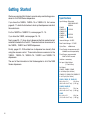
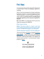
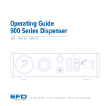
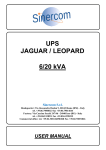
Operating Guide
1500 Series Dispenser
1500XL
•
1500XL-15
•
1500XL-CA
•
1500DV-15
•
1500D
®
US & Canada: 800-556-3484
A NORDSON COMPANY
In the UK: 0800 585733
In Mexico: 001-800-556-3484
Introduction
The advanced 1500 Series dispensers provide years of trouble-free,
productive service. This Operating Guide will help you maximize the
usefulness of your new dispenser.
Please spend a few minutes to become familiar with the controls and
features of your new dispenser. Follow our recommended testing
procedures. Review the helpful information we have included based
on over 30 years of industrial dispensing experience.
Most questions you will have are answered in this Guide. However,
if you need assistance, please do not hesitate to contact EFD or your
authorized EFD distributor.
☎
US & Canada, call 800-556-3484.
In Mexico, call 001-800-556-3484.
In the UK, ring free 0800 585733.
The EFD Pledge
We pledge that you will be completely satisfied with our products.
We endeavor to ensure that every EFD product is produced to our
no-compromise quality standards.
If you feel that you are not receiving all the support you require,
or if you have any questions or comments, I invite you to write or call
me personally.
Our goal is to build not only the finest equipment and components,
but also to build long-term customer relationships founded on
superb quality, service, value and trust.
Peter Lambert, President
Contents
Getting Started ............................................................................. 4
Specifications
First Steps .................................................................................... 5
Unpacking the Dispenser & Activating your Ten Year No-fault Warranty
Microprocessor Control ............................................................. 6-7
How to Use the Display and Control Pad
1500XL - Setup & Use ................................................................. 8
Hookup ............................. 8-9
Setup for Testing .......... 10-11
1500DV - Setup & Use ............................................................... 12
Hookup ......................... 12-13
Setup for Testing .......... 14-15
1500D - Setup & Use ................................................................. 16
Hookup ......................... 16-17
Setup for Testing .......... 18-19
Testing the Dispensers ......................................................... 20-21
Making Timed Deposits of Medium to Thick Fluids
Changing Deposit Size and Drawing Stripes
Programming Deposit Size
How to Use the Vacuum Control ........................................... 22-23
Making Timed Deposits of Watery-thin Fluids
ULTRA Dispensing System ................................................... 24-25
Loading the Barrel Reservoirs ............................................... 26-27
1500XL and 1500D Schematics & Parts .................................... 28
1500DV Schematic & Parts ........................................................ 29
How the 1500 Series Dispensers Work ..................................... 30
This manual is for the express and sole use of EFD
dispenser purchasers and users, and no portion of
this manual may be reproduced in any form.
EFD, ULTRA System, LV Barrier, SmoothFlow,
ZeroDraft, SafetyLok, SnapLok and DispenStand
are trademarks of EFD Inc. ©2006 EFD, Inc.
Reordering Components ............................................................ 31
Ten Year No-fault Warranty ....................................................... 32
Meets applicable CSA and CE requirements.
3
Getting Started
We have organized this Guide to provide setup and testing procedures for the 1500 Series dispensers.
If you have the 1500XL, 1500XL-15 or 1500XL-CA, first review
pages 8 - 11 which illustrate how to hook up the dispenser and what
the controls do.
For the 1500DV or 1500DV-15, review pages 12 - 15.
If you have the 1500D, review pages 16 - 19.
Specifications
Input Voltage: Selectable
100/120/220 VAC
50/60Hz
1500XL
14/12VA
1500XL-15
1500XL-CA
1500DV
18/15VA
1500DV-15
1500D
14/12VA
Next, pages 20 - 21 show how to dispense the thick paste-like test
material included in the Test Kit. These instructions are common to
the 1500XL, 1500DV and 1500D dispensers.
Internal Voltage: 24 VDC
Finally, pages 22 - 23 illustrate how to dispense low viscosity fluid
using the vacuum control. These instructions are common to the
1500XL, 1500XL-15, 1500XL-CA, 1500DV and 1500DV-15
dispensers.
Time Control: microprocessor with
0.00005 second repeatability
The rest of the information in this Guide applies to all of the 1500
Series dispensers.
Foot Pedal Voltage: 5.5 VDC
Cycle Rate:
>600/minute
Time Range: programmable
0.001 to 99.9 seconds
Initiation: momentary
Air Input: 80 to 100 psi
(5.5 to 6.9 bar)
Air Output:
1500XL, 1500DV, 1500D
0 to 100 psi (0 to 6.9 bar)
1500XL-15, 1500XL-CA, 1500DV-15
0 to 15 psi (0 to 1.0 bar)
1500XL, 1500XL-15, 1500XL-CA
10⅜ x 8½ x 2⅝˝
4 lb 14 oz
(26.4 x 21.6 x 6.7 cm) (2.21 kg)
4
1500DV, 1500DV-15
10⅜ x 8½ x 2⅝˝
(26.4 x 21.6 x 6.7 cm)
5 lb 2 oz
(2.32 kg)
1500D
8⅝ x 8½ x 2⅝˝
(21.9 x 21.6 x 6.7 cm)
4 lb 2 oz
(1.87 kg)
First Steps
First: Unpack and use the checklist enclosed with the Dispenser Kit
to identify all items. If there is any discrepancy, please call us
immediately.
Second: Power and compressed plant air should be available where
the dispenser is to be set up. Air pressure should be between 80 and
100 psi (5.5 and 6.9 bar). If you are not using an EFD five-micron filter
regulator #2000F755, be certain your plant air is properly filtered
and dry and a regulated, constant air pressure is supplied to the
dispenser.
Note: Model 15000XL-CA is supplied with an EFD five-micron filter
regulator with coalescing filter (#2000F756).
Bottled nitrogen can be used.
Warning: If high pressure bottled air or nitrogen is used, a high
pressure regulator must be installed on the bottle and set at 100 psi
maximum. The 2000F755 filter regulator is not recommended.
Check the voltage label to be certain it is set to the available power.
Third: Now is a good time to ACTIVATE your extended Ten (10) Year
No-fault Warranty. Please fill in and return the postage paid
Warranty card. Or if you prefer, call the appropriate toll-free number
listed below, provide the serial number of your dispenser and
respond to a few short questions. You are then assured of complete
protection for 10 years.
☎
US & Canada, call 800-556-3484.
In Mexico, call 001-800-556-3484.
In the UK, ring free 0800 585733.
5
Microprocessor Control
Once your dispenser is set up, return to these pages to familiarize
yourself with the various functions of the microprocessor controls.
Disconnect the male quick-connect on the barrel adapter hose from
the dispenser before testing each function to prevent inadvertent
fluid dispensing.
❶ Program mode
Press to clear the display. Any
decimals will disappear and the
time range will reset to 000. Display alternates bright and dim to
indicate the program mode.
❷ Timer bypass mode
Press once and the display
changes to - - - (dashes). Foot
pedal now controls liquid flow.
Press again and dashes are
replaced by previously set time.
6
❷
❸
0. 2
5
❺
❻
❶
❹
❸ Decimal button
Press to move decimal. When
no decimal shows, time range is
.000 to .999 seconds.
❹ ❺ ❻ Time set buttons
Each button sequentially controls the display digit in that
panel. Each press advances
the display 0.....9 and repeats.
How to Use the Display and Control Pad
To change the displayed time
0
5
0
.050 seconds
0. 5
5. 0
5 seconds
button twice to zero
Press the button below each panel to set a specific time. Be sure
the decimal is in the correct place for the time you require.
(Cannot be done in program mode.)
0
0.50 seconds
0
Start by setting the digits at zero. Press the
the display.
Timer bypass mode (foot pedal control)
Press the
button, - - - (dashes) will appear. To get back in the
time mode, press again. (This mode is used for filling the tip and
making by-eye deposits. Cannot be done in program mode.)
Program mode
Press the
button once. Display flashes. Use the foot pedal to
establish deposit size (and time). Press
again, flashing stops
and programmed time is displayed. Decimal will automatically
move to appropriate position.
Change decimal position
Press the
button to move the decimal during manual time
set. No decimal shows when time range is .000 to .999 seconds.
(Cannot be done in program mode.)
To interrupt the dispense cycle
The foot pedal is pressed while dispensing. To interrupt dispensing
in mid-cycle and reset to the original time display, press the pedal
a second time.
7
Note: For hookup purposes,
connections for the 1500XL,
1500XL-15 and 1500XL-CA
models are identical.
Plant air, 125 psi maximum to
regulator. Output from regulator
should be a minimum of 80 psi,
maximum of 100 psi.
❶
Power cord
Air input
hose
❷
❹
❸
Check voltage label
on dispenser
Foot pedal
assembly
❺
Adapter
assembly
1500XL
❼
❻
Blue
test fluid
8
Male quick-connect,
insert and twist to lock
1500XL -- Hookup
Spare Fuse
1500XL
❶ Connect the air input hose to a plant air source. Set plant air
supply within 80 to 100 psi (5.5 to 6.9 bar). Where required, use
an EFD five-micron filter regulator #2000F755 (see Warranty).
❷ Attach the air input hose coupling to the dispenser. Pull back
120
22
0
metal ring to attach to dispenser.
10
0
❸ Plug in the polarized foot pedal connector.
❹ Check the voltage label on the input voltage selector cartridge.
To change the voltage, remove the voltage selector from the
cartridge, rotate it and position the correct voltage to show
through the cartridge window. Replace the cartridge into the
power cord receptacle and insure that both sides snap securely
into position. Install the power cord.
Note: For 1500XL-15 and 1500XL-CA dispensers, use the test barrel
filled with clear fluid and the red 25 gage tip. Refer to "Making Timed
Deposits of Watery-thin Fluids" on page 22.
❺ Attach the 10cc barrel prefilled with blue, nontoxic test fluid
(included with the dispenser) to the 10cc adapter head.
Voltage Value
Cartridge Window
(check voltage indicated)
Note: The dispenser is
shipped with the fuse
cartridge set for 120
VAC input.
I/O Connection
The 9 pin D connector and
internal circuitry provides
external initiate with end-ofcycle feedback. The pin
connections are shown
below. For complete schematic and detailed information, please contact EFD.
5 4 3 2 1
9 8 7 6
❻ Take the 10cc adapter assembly (#5150 on the adapter head)
and insert the black, male quick-connect into the air output fitting
on the front panel and turn clockwise to lock. Place the barrel in
the barrel stand.
❼ During the initial testing, you will not use the vacuum control.
Keep this control shut off (turned completely clockwise—do not
force).
Pin
1.
2.
3.
4.
5.
6.
7.
8.
9.
Function
Initiate +
5-24 VDC
Initiate
Output + 5-24 VDC
250 mA Max
Output
Contact Closure
Chassis Ground
Contact Closure
Not Used
Not Used
]
]
Note: A 9-pin male connector
assembly is available from
EFD (order part #7154).
9
1500XL CONTROLS & CONNECTIONS
Note: The controls for the 1500XL, -15 and -CA models are identical.
Barrel
vacuum control
Air gauge
❸
Air pressure
regulator
❻
❹
❷
Air output
quick-connect
Voltage selector and
fuse cartridge
Power
switch
❶
(Refer to pages 6-7 for
detailed instructions.)
Vacuum gauge
❼
❺
Time set buttons
Foot pedal
receptacle
Male quick-connect,
insert and twist to lock
Blue
test fluid
Power input
receptacle
10
Display and
control pad
I/O 9 pin
interface
connector
Vacuum transducer/
air exhaust port
Air input
1500XL -- Setup for Testing
The amount of material dispensed each cycle depends on the
combination of air pressure, time of air pulse, viscosity of material
and dispensing tip size.
0. 2
1500XL
Power switch ❶ should be off.
5
Note: The following steps refer to the 1500XL dispenser. For the
1500XL-15 and 1500XL-CA dispensers, refer to "Making Timed
Deposits of Watery-thin Fluids" on page 22.
The first step is to remove the tip cap from the prefilled barrel of blue
test material (twist and pull). Replace it with an 18 gage (green)
tapered dispensing tip. Press the tip on and twist clockwise to lock.
Refer to pages 6 - 7 for
complete details on the
microprocessor controls.
Pull out air pressure regulator knob ❷ until it "clicks" into the
unlocked position. Turn clockwise to adjust the air pressure to 30 psi
(2.1 bar) for the initial tests.
Always set the pressure desired by turning the air regulator knob
❷ clockwise. To reduce the pressure, turn the knob counterclockwise until the gauge ❸ reads a lower pressure than desired. Then
increase and stop at desired pressure. Push knob in to lock.
Press power switch ❶ to turn on the dispenser. The digital display
will show the time that was set when the dispenser was turned off.
Set the digital time to 0.25 seconds as follows:
On the display and control pad ❹, press the decimal button
until the decimal is moved to the left and appears in the left display
segment. This puts the time range within 0.00 to 0.99 seconds. (Fig. 1)
Now, use the time set buttons ❺ to set the length of the air pulse.
Press the bottom right button until a 5 shows. Then press the bottom
middle button until a 2 shows. Finally, press the bottom left button
until a 0 shows. This display is equal to 0.25 seconds. (Fig. 2)
Be sure barrel vacuum control ❻ is turned off. In the initial tests, the
vacuum pressure gauge ❼ will indicate zero pressure.
0. 0
0
(Fig. 1)
Note: For .000 time, the
decimal is not indicated.
Instead, the 000 display
is shown.
0. 2
5
(Fig. 2)
Please continue to page 20 for test procedures.
11
Note: For hookup purposes,
the connections for the
1500DV and 1500DV-15
models are identical.
Plant air, 125 psi maximum to
regulator. Output from regulator
should be a minimum of 80 psi,
maximum of 100 psi.
❶
Power cord
❹
Check voltage label
on dispenser
Air input
hose
❷
A
❸
B
Foot pedal assembly
❺
Adapter
assembly
Blue
test fluid
1500DV
❼
❻
❽
Male quick-connect,
insert and twist to lock
Vacuum
pickup pen
Pickup tip
12
1500DV -- Hookup
❶ Connect the air input hose to a plant air source. Set plant air supply
Spare Fuse
within 80 to 100 psi (5.5 to 6.9 bar). Where required, use an EFD
five-micron filter regulator #2000F755 (see Warranty).
❷ Attach the air input hose coupling to the dispenser. Pull back metal
120
22
0
ring to attach to dispenser.
10
0
❸ Plug in the polarized foot pedal connectors (A & B).
change the voltage, remove the voltage selector from the cartridge,
rotate it and position the correct voltage to show through the
cartridge window. Replace the cartridge into the power cord
receptacle and insure that both sides snap securely into position.
Install the power cord.
Note: For the 1500DV-15 dispenser, use the test barrel filled with clear
fluid and the red 25 gage tip. Refer to "Making Timed Deposits of Waterythin Fluids" on page 22.
❺ Attach the 10cc barrel prefilled with blue, nontoxic test fluid
(included with the dispenser) to the 10cc adapter head.
Cartridge Window
(check voltage indicated)
Note: The dispenser is
shipped with the fuse
cartridge set for 120
VAC input.
1500DV
❹ Check the voltage label on the input voltage selector cartridge. To
Voltage Value
I/O Connection
The 9 pin D connector and
internal circuitry provides
external initiate with end-ofcycle feedback. The pin
connections are shown
below. For complete schematic and detailed information, please contact EFD.
5 4 3 2 1
9 8 7 6
❻ Take the 10cc adapter assembly (#5150 on the adapter head) and
insert the black, male quick-connect into the air output fitting on the
front panel and turn clockwise to lock. Place barrel in the barrel stand.
❼ During the initial testing, you will not use the barrel vacuum control.
Keep this control shut off (turned completely clockwise—do not force).
❽ Plug in the vacuum pickup pen. Select and attach a pickup pad/tip.
Pin
1.
2.
3.
4.
5.
6.
7.
8.
9.
Function
Initiate +
5-24 VDC
Initiate
Output + 5-24 VDC
250 mA Max
Output
Contact Closure
Chassis Ground
Contact Closure
Not Used
Not Used
]
]
Note: A 9-pin male connector
assembly is available from
EFD (order part #7154).
13
1500DV CONTROLS & CONNECTIONS
Note: The controls for the 1500DV and 1500DV-15 models are identical.
Barrel
vacuum control
❻
Air pressure
regulator
Air gauge
❸
❹
❷
Voltage selector and
fuse cartridge
Power
switch
❶
14
detailed instructions.)
Time set buttons
Pickup pen
vacuum control
❼
Pickup pen
quick connect
A. Dispense foot pedal
receptacle
B
Pickup pen
vacuum
transducer
(Refer to pages 6-7 for
❺
Barrel air output
quick-connect
B. Vacuum foot pedal
receptacle
Display and
control pad
A
Power input
receptacle
I/O 9 pin
interface
connector
Barrel vacuum
transducer
Air Input
1500DV -- Setup for Testing
Power switch ❶ should be off.
The amount of material dispensed each cycle depends on the combination of air
pressure, time of air pulse, viscosity of material and dispensing tip size.
The first step is to remove the tip cap from the prefilled barrel of blue test material
(twist and pull). Replace it with an 18 gage (green) tapered dispensing tip. Press
the tip on and twist clockwise to lock.
Pull out air pressure regulator knob ❷ until it "clicks" into the unlocked position.
Turn clockwise to adjust the air pressure to 30 psi (2.1 bar) for the initial tests.
Always set the pressure desired by turning the air regulator knob ❷ clockwise.
To reduce the pressure, turn the knob counterclockwise until the gauge ❸ reads
a lower pressure than desired. Then increase and stop at desired pressure.
Push knob in to lock.
0. 2
5
Refer to pages 6 - 7 for
complete details on the
microprocessor controls.
1500DV
Note: The following steps refer to the 1500DV dispenser. For the 1500DV-15
dispenser, refer to "Making Timed Deposits of Watery-thin Fluids" on page 22.
Press power switch ❶ to turn on the dispenser. The digital display will show
the time that was set when the dispenser was turned off.
Set the digital time to 0.25 seconds as follows:
On the display and control pad ❹, press the decimal button
until the
decimal is moved to the left and appears in the left display segment. This puts
the time range within 0.00 to 0.99 seconds. (Fig. 1)
Now, use the time set buttons ❺ to set the length of the air pulse. Press the
bottom right button until a 5 shows. Then press the bottom middle button until
a 2 shows. Finally, press the bottom left button until a 0 shows. This display is
equal to 0.25 seconds. (Fig. 2)
Be sure barrel vacuum control
❻ is turned off.
Note: A separate vacuum control ❼ powers the pickup pen. The second foot
pedal B turns on the solenoid that controls the vacuum. Turn the control
counterclockwise until sufficient vacuum is obtained. Place the pad on the
component and press the foot pedal to provide pickup vacuum. Position the
component where needed and release the foot pedal.
Please continue to page 20 for test procedures.
0. 0
0
(Fig. 1)
Note: For .000 time, the
decimal is not indicated.
Instead, the 000 display
is shown.
0. 2
5
(Fig. 2)
15
Plant air, 125 psi maximum to
regulator. Output from regulator
should be a minimum of 80 psi,
maximum of 100 psi.
❶
Power cord
❹
Check voltage label
on dispenser
Air input
hose
❷
❸
Foot pedal
assembly
❺
Adapter
assembly
1500D
Blue
test fluid
16
❻
Male quick-connect,
insert and twist to lock
1500D -- Hookup
❶ Connect the air input hose to a plant air source. Set plant air
Spare Fuse
supply within 80 to 100 psi (5.5 to 6.9 bar). Where required, use
an EFD five-micron filter regulator #2000F755 (see Warranty).
❷ Attach the air input hose coupling to the dispenser. Pull back
120
22
0
metal ring to attach to dispenser.
10
0
❸ Plug in the polarized foot pedal connector.
❹ Check the voltage label on the input voltage selector cartridge.
To change the voltage, remove the voltage selector from the
cartridge, rotate it and position the correct voltage to show
through the cartridge window. Replace the cartridge into the
power cord receptacle and insure that both sides snap securely
into position.
Install the power cord.
❺ Attach the 10cc barrel prefilled with blue, nontoxic test fluid
(included with the dispenser) to the 10cc adapter head.
Voltage Value
Cartridge Window
(check voltage indicated)
Note: The dispenser is
shipped with the fuse
cartridge set for 120
VAC input.
I/O Connection
The 9 pin D connector and
internal circuitry provides
external initiate with end-ofcycle feedback. The pin
connections are shown
below. For complete schematic and detailed information, please contact EFD.
5 4 3 2 1
9 8 7 6
and insert the black, male quick-connect into the air output fitting
on the front panel and turn clockwise to lock. Place the barrel in
the barrel stand.
Function
Initiate +
5-24 VDC
Initiate
Output + 5-24 VDC
250 mA Max
Output
Contact Closure
Chassis Ground
Contact Closure
Not Used
Not Used
]
]
1500D
❻ Take the 10cc adapter assembly (#5150 on the adapter head)
Pin
1.
2.
3.
4.
5.
6.
7.
8.
9.
Note: A 9-pin male connector
assembly is available from
EFD (order part #7154).
17
1500D CONTROLS & CONNECTIONS
Air gauge
❸
Air pressure
regulator
❹
❷
Air output
quick-connect
Voltage selector and
fuse cartridge
Power input
receptacle
18
Power
switch
❶
Display and
control pad
(Refer to pages 6-7 for
detailed instructions.)
❺
Time set buttons
Foot pedal
receptacle
I/O 9 pin interface
connector
Air input
1500D -- Setup for Testing
Power switch ❶ should be off.
The amount of material dispensed each cycle depends on the
combination of air pressure, time of air pulse, viscosity of material
and dispensing tip size.
Pull out air pressure regulator knob ❷ until it "clicks" into the
unlocked position. Turn clockwise to adjust the air pressure to 30 psi
(2.1 bar) for the initial tests.
Always set the pressure desired by turning the air regulator knob
❷ clockwise. To reduce the pressure, turn the knob counterclockwise until the gauge ❸ reads a lower pressure than desired. Then
increase and stop at desired pressure. Push knob in to lock.
Press power switch ❶ to turn on the dispenser. The digital display
will show the time that was set when the dispenser was turned off.
Set the digital time to 0.25 seconds as follows:
On the display and control pad ❹, press the decimal button
until the decimal is moved to the left and appears in the left display
segment. This puts the time range within 0.00 to 0.99 seconds. (Fig. 1)
Now, use the time set buttons ❺ to set the length of the air pulse.
Press the bottom right button until a 5 shows. Then press the bottom
middle button until a 2 shows. Finally, press the bottom left button
until a 0 shows. This display is equal to 0.25 seconds. (Fig. 2)
0. 2
5
Refer to pages 6 - 7 for
complete details on the
microprocessor controls.
0. 0
0
(Fig. 1)
Note: For .000 time, the
decimal is not indicated.
Instead, the 000 display
is shown.
0. 2
5
1500D
The first step is to remove the tip cap from the prefilled barrel of blue
test material (twist and pull). Replace it with an 18 gage (green)
tapered dispensing tip. Press the tip on and twist clockwise to lock.
(Fig. 2)
Please continue to page 20 for test procedures.
19
Testing the Dispensers
Making Timed Deposits of Medium to Thick Fluids
(1500XL, 1500DV and 1500D)
- - (Fig. 1)
You are now ready to test the prefilled, nontoxic, blue test fluid. This
material is representative of thick, non-leveling fluids like sealants,
pastes or greases.
Timer
Pressure
30
Check your initial settings:
2
0. 2
5
0. 2
5
(Fig. 2)
A) Air gauge reads 30 psi.
B) Timer is set at 0.25 (refer to page 6
for complete details on the microprocessor controls).
C) Green tapered tip is on the test barrel.
D) Press the timer bypass button
once so that dashes
appear in the display segments. (Fig. 1)
Holding the barrel as shown, rest the tip on a piece of paper. Press
the foot pedal until the tip fills and some fluid is pushed out onto the
paper. Repeat this whenever you change to a new tip.
Correct angle for consistent deposits.
With the tip filled, re-press the timer bypass button
and the
dashes will be replaced by the dispense time previously set. (Fig. 2)
Take the Dot Test sheet and put the tip on a 1/4" circle, holding the
barrel as shown. Press the foot pedal. Check the dot size. Make
several more similar dots and note the size consistency.
Changing Deposit Size, Drawing Stripes
The dot size is determined by the tip diameter, the output air
pressure setting and the pulse time. For large dots, use a large tip,
higher pressure and more time. Normally, you want to use as short
a time pulse as possible. To increase the dot size, slightly increase
output air pressure, or increase tip size, or both.
To make stripes, press the timer bypass button
. Dashes replace
the time indication. With the tip in contact with the test sheet, press
and hold down the foot pedal while making a bead or stripe.
20
Remember - always bring the tip
into contact with the work surface
at the illustrated angle. After the tip
is in position, press the foot pedal.
Release pedal and remove tip by
lifting straight up.
Green Tip Settings
Time
Dot Tests - Use the convenient Dot Test sheet included.
Test
Pressure
Dot Size
A
30 psi
0. 2
5
B
20 psi
0. 2
5
First, follow the settings illustrated on the left, and you will get dots
about the size shown. Try other times and pressures to see how
easy it is to get just the dot size you want.
C
20 psi
0. 1
0
Dot Test with Blue Tapered Tip
D
15 psi
0. 1
0
These tests show the effect of using a smaller diameter tip.
Dot Test with Green Tapered Tip
Blue Tip Settings
Test
Pressure
Time
E
30 psi
0. 1
5
F
20 psi
0. 1
5
G
20 psi
0. 1
0
Dot Size
Replace the green tip with the blue tapered tip. Now, press the timer
bypass button
(dashes appear) and press the foot pedal to fill
the tip. Then, press the bypass button to restore time last used
(0.10). Press the bottom right button to change from a 0 to a 5.
Time displayed now shows 0.15. (For Test G, change the time back
to 0.10).
Programming Deposit Size
0
0
(Fig. 1)
0
Press the program button
(top left). This zeros out the display
and you will see 000 (Fig. 1). The decimal will not show. Note that
the display flashes bright/dim. This flashing indicates you are in the
program mode.
Position the tip on the largest test circle. Press the foot pedal and
when the test fluid fills the circle, release the foot pedal. Note the
time on the flashing display. Press the program button
once.
The time remains and the flashing stops.
Position the tip and momentarily press the foot pedal. The displayed
time zeros and counts up to and stops at the programmed time. This
time will be repeated each time the foot pedal is pressed.
To change dispensing time, either enter the program mode to zero
out the display, or change the displayed digits by pressing the
buttons below them.
21
How to Use the Vacuum Control
Making Timed Deposits of Watery-thin Fluids
(1500XL, 1500XL-15, 1500XL-CA 1500DV, 1500DV-15)
The vacuum control allows low viscosity liquids, even water, to be
consistently dispensed without dripping between cycles. The vacuum
exerts a negative pressure on the liquid in the barrel and prevents
dripping.
Insert LV
Barrier™
Remove
orange
end cap
Air gap
For these tests, you will use the test barrel with the clear fluid.
Remove
tip cap
1. While holding the barrel upright in one hand, remove the orange
end cap and insert the blue LV Barrier.™ Allow an air gap as
shown.
2. Attach the barrel to the 10cc adapter. Snap the safety clip tightly
closed to prevent any dripping or bubbling. Remove the tip cap
and attach the 25 gage (red) tip.
3. Set air pressure at 5 psi, and the time at 0.14 (Fig. 1).
4. Press the timer bypass button
(dashes appear).
5. With the barrel pointing downward over a container, unsnap the
safety clip. Then press the foot pedal to fill the tip.
6. If a drop begins to form at the end of the tip, slowly turn the
vacuum control knob counterclockwise to stop the drop from
growing. Wipe the tip and adjust vacuum as necessary. Normally, only 1 to 2 psi of vacuum pressure is necessary.
7. Press the timer bypass button
pense time (Fig. 1).
to return to the preset dis-
8. Take the barrel and place the tip on the test sheet. Press the foot
pedal. Check the dot size. Increase or decrease by adjusting
pressure or time.
22
0. 1
(Fig. 1)
4
Three things to remember
If you do not use the piston
when dispensing thin fluids:
If you choose not to use the piston, please follow these instructions
carefully:
1. While holding the barrel upright in one hand, twist on an orange
tip cap. Using the small funnel, fill about 2/3 full with your fluid.
2. Open the safety clip and attach the barrel to the 10cc adapter.
3. Close the safety clip as tight as possible.
4. Increase vacuum by turning vacuum control knob counterclockwise and set to 1.5 on the vacuum pressure gauge.
Do not tip the barrel upside down
or lay flat. This will cause the
liquid to run into the dispenser.
Open
When changing tips
or attaching a tip cap,
snap the safety clip
completely closed to
prevent any dripping
or bubbling.
Closed
5. Then, without tipping the barrel upside down, remove the tip
cap and attach the 25 gage (red) tip.
6. Open the safety clip. Your material may begin to bubble.
Reduce vacuum by turning vacuum control knob clockwise.
7. If a drop begins to form at the end of the tip, slowly turn the
vacuum control knob counterclockwise to stop the drop from
growing. Wipe the tip and adjust vacuum as necessary.
Now the fluid is in proper balance. It does not bubble or drip.
Use an EFD filter trap
(#1000FLT-Y). This
filter trap will impede
the flow should the
low viscosity liquid be
sucked back towards
the dispenser.
Repeat tests as before, keeping the air pressure low and adjusting the time for different deposit sizes. Contact EFD if you have
any questions.
☎
US & Canada, call 800-556-3484.
In Mexico, call 001-800-556-3484.
In the UK, ring free 0800 585733.
IMPORTANT
Regardless of the fluid viscosity, using the correct EFD piston will give you better results.
White SmoothFlow™ piston for most fluids, blue LV Barrier™ for watery-thin fluids and
orange flat wall piston for thick, stringy fluids. See pages 24 - 25 for a complete description
of how EFD pistons work and the benefits they can bring to your operation.
23
TM
Advanced Dispensing System
If you dispense thick fluids, several problems may
occur. First, the repetitive air cycles can bore
tunnels through non-leveling fluids, causing spitting and inconsistent deposits. Second, thick fluids
contain trapped air that leads to drooling and
oozing.
For Thick Fluids
Air Pressure
ON
Air Pressure
OFF
These problems are eliminated by using the
SmoothFlow™ piston. That's because the white
pistons prevent tunneling by providing a barrier to
the pulsed-air cycles, and prevent oozing by
responding to the pressure of trapped air with a
slight suck-back movement after the dispense
cycle.
The white piston is used for most fluids.
However, if you are applying RTV silicone and find
that the piston bounces and causes stringing,
switch to the orange, flat wall piston.
The SmoothFlow™ pistons make barrel filling easier,
too. As you load the fluid in, air is trapped in the
bottom and throughout the fluid. Simply insert a
SmoothFlow™ piston and gently press down on the
fluid as far as possible. This action forces out most
of the air and results in consistent deposits.
24
No drip or
ooze.
If you use low to medium viscosity fluids, the white
SmoothFlow™ piston has several advantages.
First, vacuum adjustment is much less sensitive.
Second, the piston prevents fumes from the fluid
being exhausted into the work environment. Third,
the piston prevents fluid backflow into the dispenser if the barrel is inadvertently turned upside
down. Fourth, using the piston makes it easy and
safe to change tips without dripping.
Note: If you use watery-thin fluids such as solvents,
cyanoacrylates and anaerobics, specify the ULTRA
System™ with the blue LV Barrier™. Available in
3cc and 10cc sizes.
For Cyanoacrylates
or Watery-thin Fluids
For Thin Fluids
SmoothFlow™ piston
prevents fluid backflow.
Fumes cannot escape.
No air gap when using
the SmoothFlow™ piston.
Blue LV Barrier™ for improved
control of very low viscosity fluids.
Note: The LV Barrier ™ works best
with an air gap between the barrier
and fluid.
Maximum 1/2 fill
Note: If you choose not to use a piston,
please refer to page 23 for instructions.
25
Loading the Barrel Reservoirs
Caution: Do not completely fill barrels. The optimum fill is a maximum 2/3 of the barrel capacity and 1/2 of the barrel capacity when
using the LV Barrier™.
If the fluid you are dispensing is pourable, take the barrel, twist on
a tip cap and pour your fluid in. If appropriate, insert the SmoothFlow™
piston (see page 24). Carefully press the piston down until it
contacts the fluid. The barrel is now ready for use.
If you are dispensing solvents, cyanoacrylates or anaerobics, use
the LV Barrier™. Place barrier in the top of the barrel reservoir. Allow
air between barrier and fluid. Do not contact the barrier to the fluid.
If your fluid is thick or non-leveling, you can spoon it into the barrel
with a spatula Or, if the fluid comes packed in a 1/10 gallon
cartridge, try loading the barrel with a caulking gun. Then press in
the SmoothFlow™ piston to move the fluid to the bottom of the barrel
and to remove trapped air.
Fill procedure for thick fluids
(shown: caulking gun)
2/3
maximum
fill
Fill procedure for
pourable fluids
LV Barrier™
Air gap
1/2 maximum fill
2/3
maximum
fill
26
Fill procedure for cyanoacrylates
or watery-thin fluids
White
SmoothFlow™
piston
EFD offers productive alternatives to traditional barrel loading methods. Here are a few suggestions that can help keep your work area
clean, save time and reduce the chance of entrapped air in the fluid.
1. You could use the EFD #920BL Barrel Loader. Pack the fluid into
the 12 ounce cartridge as shown. Then place the prefilled
cartridge into the barrel loader. Using air pressure, the barrel
loader fills the barrel (with piston) from the bottom up.
Filling the cartridge
for the barrel loader
If the fluid comes packed in a 1/10 gallon (300 ml.) caulking type
cartridge, use the EFD #940BL Barrel Loader.
2. For fast, accurate volumetric filling, the 8000BF Barrel Filling
Station can be used with any pressure reservoir or cartridge.
Recommended for high production barrel filling.
3. If you receive frozen epoxies or other fluids in medical type
syringes with a manual plunger, request our luer-to-luer fitting
#2160 to transfer the material.
POSITION BAND
ABOVE LINE
55cc
Please call an EFD Product Specialist for additional assistance.
30cc
10cc
5cc
3cc
2/3 Maximum
Fill
EFD #920BL Barrel Loader
(Specify #940BL for prefilled 1/10 gal. caulking tubes)
7
8
6
50
9
60
40
0.6
3
4
4
11
20
0.2
80
3
5
2
0.8
12
Power
70
0.4
10
5
30
Start
14
15
Cylinder Pressure
90
1
7
0
0
Start Fill
10
1.0
1
Stop Fill
10
0
2
13
6
Stop
Fluid Pressure
Barrel Fill Station
EFD #8000BF Barrel Filling Station
#2160 Luer-to-luer fitting
Barrel Rack
#905BR for 3cc & 5cc barrels
#910BR for 10cc, 30cc and 55cc barrels
27
Schematics and Parts
1500XL, 1500XL-15, 1500XL-CA, 1500D
Replacement Parts List
Models 1500XL, 1500XL-15, 1500XL-CA
12
5
7 22
6
24
10
11
26
13
1
18
20
8
6
2
19
16
9
23
25
21
Model 1500D
12
5
7
6
4
11
10
Gauge 0 to 15 psi (0 to 1.0 bar)
Gauge 0 to 100 psi (0 to 6.9 bar)
4. 2-2003-24D
1500D solenoid assembly
5. 2081A
Male mini air coupler-panel mount
6. 2087
Fitting 1/8 NPTM x 1/4 barb elbow brass
7. 2086
Fitting 1/8 NPTM x 1/4 barb 90° brass
8. 2036
Fitting 1/8 NPTF x 1/4 barb brass
9. 2004B
Female quick-connect, black
10. 7109
Power switch
11. 2-2017-1500
Foot pedal receptacle assembly
12. 7111
Fuse .125A
13. 2019
Dispenser end panel
14. 2002SCR
Replacement screen for regulator*
15. 2009-A24
Input cord, detachable*
16. 2015A
Foot pedal assembly*
17. 2178
Fitting 1/8 NPTM x 1/4 barb elbow brass
18. 2084
Air restrictor
19. 2-2176-1500
Barrel vacuum control
20. 2088
Fitting 1/8 NPTF x 1/4 barb brass
21. 2001B
Gauge 0 to 15 psi (0 to 1.0 bar)
22. 2170
Vacuum transducer
23. 2-2002-1500 0 to 100 psi (0 to 6.9 bar) regulator
2-2002A-1500 0 to 15 psi (0 to 1.0 bar) regulator
26
1
1/4" OD x .160" ID tubing
2. 2001B
2001C
3. 2-2002-1500D 1500D regulator assembly
6
17
1. 2024-160
13
24. 2-2003-24XL
1500XL solenoid assembly
25. 2-2006DB-D
Display board assembly
26. 2-2006PS-D
Power supply board assembly
* Not Shown
8
6
6
2
28
3
9
25
14
Input Air
Regulated Air
Vacuum
Schematic and Parts
1500DV, 1500DV-15
Replacement Parts List
1. 2024-160
Models 1500DV, 1500DV-15
14
1/4" OD x .160" ID tubing
2. 2001B
2001C
Gauge 0 to 15 psi (0 to 1.0 bar)
Gauge 0 to 100 psi (0 to 6.9 bar)
3. 2-2003-24XL
1500XL solenoid assembly
4. 2-2003-15DV
Pickup solenoid assembly
6
23
7
Male mini air coupler-panel mount
7. 2087
Fitting 1/8 NPTM x 1/4 barb elbow brass
8. 2086
Fitting 1/8 NPTM x 1/4 barb 90° brass
9. 2085
Fitting 1/8 NPTM x 1/4 barb elbow, low profile
10. 2036
Fitting 1/8 NPTF x 1/4 barb brass
11. 2004B
Female quick-connect, black
12. 7109
Power switch
13. 2-2017-15DV
Foot pedal receptacle assembly
14. 7111
Fuse .125A
15. 2019
Dispenser end panel
16. 2002SCR
Replacement screen for regulator*
17. 2009-A24
Input cord, detachable*
18. 2-2015F
Dual foot pedal assembly*
19. 2178
Fitting 1/8 NPTM x 1/4 barb elbow brass
20. 2084
Air restrictor
21. 2-2176-15DV
Barrel vacuum control
22. 2-2176-15PU
Pickup vacuum control
23. 2170
Vacuum transducer
24. 2032
Fitting 1/8 NPTM x 1/4 barb brass
25. 2-2006DB-D
Display board assembly
26. 2-2006PS-D
Power supply board assembly
27. 2-2017-1500
Foot pedal receptacle assembly
12
27
13
7
5. 2-2002-15DV 0 to 100 psi (0 to 6.9 bar) regulator
2-2002A-15DV 0 to 15 psi (0 to 1.0 bar) regulator
6. 2081A
23
8
3
8
9
15
26
1
4
24
20
19
10
5
2
9
9
7
21
22
11
17
25
11
Input Air
Regulated Air
Vacuum
* Not Shown
29
How the 1500 Series Dispensers Work
With the air connected and the power on, here’s what happens when you
press the foot pedal.
(1) The digital solid-state timer is energized and begins dispense cycle
countdown.
(2) The timer opens a solenoid and closes the vacuum pressure for all
1500 Series dispensers except the 1500D, allowing preset air pressure to flow to the barrel reservoir.
(3) The air pressure pushes the liquid out the dispensing tip.
(4) At the end of the preset time, the timer shuts off, closing the solenoid
and exhausting the air in the barrel.
Note: For all 1500 Series dispensers except the 1500D, the vacuum
is created by air pressure bleeding through the vacuum transducer.
The amount of vacuum is controlled by a vacuum control.
This completes the pulse cycle.
When the timer bypass button is pressed and the display shows dashes,
the microprocessor switches to direct solenoid control by the foot pedal. As
long as the foot pedal is pressed, the solenoid remains open, providing a
bypass flow of liquid for filling or striping.
Suggestions & Reminders
1. Always use an EFD piston to make barrel loading, dispensing and
handling cleaner, safer and more accurate.
Caution (for all 1500 Series dispensers except the 1500D): If you dispense
watery-thin liquids and do not use LV Barriers™—do not increase vacuum
pressure rapidly and do not tip the barrel. Vacuum may pull fluid into the
air hose; or when tipped, fluid may run back into the dispenser.
2. Always use new barrels and tips. Carefully dispose of after use. This
procedure ensures maximum cleanliness, prevents contamination
and provides proper safety.
3. To ensure smooth fluid flow from the tip and to make consistent
deposits, always have the tip at about 45° to the work surface.
30
ULTRA System™ Dispensing Components
For complete selection and technical details, please refer to EFD Catalog and price list.
Barrel adapter assemblies
General purpose precision tips
Molded one-piece, yellow, SnapLok™ adapter head with
Buna N O-ring, flexible 5/32" O.D. hose, male quickconnect and safety clip.
All EFD dispensing tips incorporate the unique
SafetyLok™ color-coded polypropylene hubs.
Conveniently packaged (50) tips per see-through
box for easy part identification.
size
with 3-ft hose
with 6-ft hose
3cc
5cc
10cc
30cc/55cc
1000Y5148
1000Y5149
1000Y5150
1000Y5152
1000Y5148-6
1000Y5149-6
1000Y5150-6
1000Y5152-6
gage
Barrels /pistons
Each box contains the same quantity of barrels and
pistons.
Thin to thick fluids (white SmoothFlow™ piston).
size
clear
UV-block
amber
opaque
black
sets/
box
3cc
5cc
10cc
30cc
55cc
5109CP-B
5110CP-B
5111CP-B
5112CP-B
5113CP-B
5109AP-B
5110AP-B
5111AP-B
5112AP-B
5113AP-B
5109UP-B
5110UP-B
5111UP-B
5112UP-B
n/a
50
40
30
20
15
Cyanoacrylates and watery-thin fluids (blue LV Barrier™)
size
3cc
10cc
clear barrel, LV Barrier™ & tip cap
5109LV-B
5111LV-B
sets/box
50
30
Smooth-flow tapered tips
Molded polyethylene with UV block. Packaged (50) tips
per see-through box for easy part identification.
gage
14
16
18
20
22
25
ID
.063"
.047"
.033"
.023"
.016"
.010"
tapered
color
5114TT-B
5116TT-B
5118TT-B
5120TT-B
5122TT-B
5125TT-B
olive
grey
green
pink
blue
red
14
15
18
20
21
22
23
25
27
30
ID
.061"
.054"
.033"
.024"
.020"
.016"
.013"
.010"
.008"
.006"
1/2" length
hub color
5114-B
5115-B
5118-B
5120-B
5121-B
5122-B
5123-B
5125-B
5127-B
5130-B
olive
amber
green
pink
purple
blue
orange
red
clear
lavender
Useful accessories
#2000F755: Five micron filter
regulator provides proper air
filtering for all dispensers.
Order if you do not have dry,
clean, filtered factory air supply.
#2000F756: Five micron filter
regulator with coalescing filter.
Removes liquid aerosols from
air supply for cyanoacrylate
applications. (Supplied with
1500XL-CA dispenser.)
#7300A: Barrel stand, fully
adjustable three axes
#DS1400:
DispenStand™
holds dispenser
vertically.
2000F755
2000F756
7300A
DS1400
#DS1200:
Horizontal stand tilts dispenser
at a 14° angle for convenient
viewing and operation.
31
EFD Ten Year No-fault Warranty
All components of EFD 1500 Series dispensers are warranted to the original
end user for ten years from date of purchase.
Within the period of this warranty, EFD will repair or replace free of charge any
defective component, regardless of fault, on return of the part, or the complete
dispenser, prepaid to the factory.
In no event shall any liability or obligation of EFD arising from this warranty
exceed the purchase price of the equipment. Before using, user shall
determine the suitability of the product for its intended use, and user assumes
all risk and liability whatsoever in connection therewith. This warranty is valid
only when clean, dry, filtered air is used.
EFD makes no warranty whatsoever of merchantability or fitness for a
particular purpose. In no event shall EFD be liable for incidental or
consequential damages.
®
A NORDSON COMPANY
Headquarters: 977 Waterman Avenue, East Providence, RI 02914-1342 USA
US & Canada: 800-556-3484 Mexico: 001-800-556-3484
Telephone: 401-434-1680 Fax: 401-431-0237
e-mail: [email protected] www.efd-inc.com
Sales and service of EFD dispensers and
dispensing components is available through
EFD authorized distributors in over 30 countries. Please contact EFD U.S.A. for specific
names and addresses.
Printed on
recycled paper
©2006 EFD Inc. 1500-MAN-01
Unit 14, Apex Business Centre, Boscombe Road
Dunstable, Bedfordshire LU5 4SB UK
Telephone: 01582 666334 Fax: 01582 664227
Freephone: 0800 585733 From Ireland: 00800 8272 9444
e-mail: [email protected] [email protected]
This equipment is regulated by the European Union under WEEE Directive (2002/96/EC).
See International
EFD
www.efd-inc.com
Inc. is incorporated
for information
withabout
limitedhow
liability
to properly
in the
dispose of this equipment.
U.S.A.