1
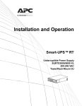
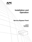
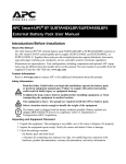
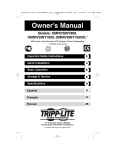
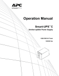
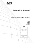
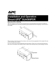
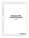
Installation and Operation Smart-UPS® Uninterruptible Power Supply Tower/Rack-Mount 2U SURTA 1500XL/1500RMXL2U/1500XLJ 2200XL/2200RMXL2U su0541a 100/120 Vac This manual and the safety guide are available in English on the enclosed CD and the APC Web site, www.apc.com. Este manual y la guía de seguridad están disponibles en español en el CD adjunto y en el sitio Web de APC, www.apc.com. Ce manuel et le guide de sécurité sont disponibles en français sur le CD-ROM ci-inclus et sur le site Web d'APC, www.apc.com. 本書及び安全ガイドの日本語版は、同梱の CD 及び APC の Web サイト(www.apc.com)からご覧戴けます。 ⎥ ↵ ⊗ ⊃™ ®× © ⎛⊄ ÷ ⏐∝ ⊗ ΧΔ ⎣© ΑΠΧ ⎠⊆ ∏ ⎯≤ ♦ ωωω.απχ.χομ≤ ♥∉ ⊃ 〉≈ ∝ ℘⎯ ± ⊇ √ 〈″ © ⎣ °″ ∪ ↔√ ÷ ⊗ ∉∝ ⊗∠ √ ∈ ⊗ ⎛° ± ⎯ϒ ≤ 您可以從隨附的 CD 與 APC 網站 (www.apc.com)上獲得本手冊與安全指南的中文版本ϒ ≤ Smart-UPS® Uninterruptible Power Supply Tower/Rack-Mount 2U SURTA1500XL/1500RMXL2U/1500XLJ SURTA2200XL/2200RMXL2U 100/120 Vac English Overview The APC® by Schneider Electric Smart-UPS® SURTA1500XL/2200XL is a high performance uninterruptible power supply (UPS). It provides protection for electronic equipment from utility power blackouts, brownouts, sags, and surges; small utility fluctuations and large disturbances. The UPS also provides battery backup power until utility power returns to safe levels or the batteries are fully discharged. Inventory All models 120 Vac models • UPS • PowerChute® Utility CD • Front bezel • USB communication cable • Serial communication cable • Literature kit containing: –Product documentation –Smart-UPS® User Manuals CD –Safety Guide –Warranty information Accessories Install accessories prior to connecting power to the UPS. Refer to the APC Web site, www.apc.com for available accessories. Optional accessories • External battery pack (XLBP) • USB communication cables • Network Management Card (NMC) Safety Read the Safety Guide included in the package before installing the UPS. Inspect the UPS upon receipt. Notify the carrier and dealer if there is damage. Recycle the packaging. 2 SURTA 1500XL/1500XLJ/2200XL Series 100/120 Vac Tower/Rack-Mount 2U Product Overview Front display panel Load Battery Charge Test su0311b Button or Indicator Description The ON button: has three functions. Press this button to turn on the UPS. Press this button to initiate a Cold Start. Cold Start is not a normal condition. When there is no utility power and UPS is off, press and hold this button to restore power to UPS. UPS will emit two beeps. During second beep, release the button. Press this button to initiate a Self-Test. Automatic: The UPS performs a self-test automatically when turned on, and every two weeks there after by default. During self-test, UPS briefly operates on battery power. Manual: Press and hold ON button for a few seconds to initiate self-test. The Off button: This button is used to switch UPS off. The Bypass LED illuminates indicating that the UPS is in bypass mode. Utility power is sent directly to connected equipment during bypass mode operation. Bypass mode operation is the result of an internal UPS fault, an overload condition or a selection made through NMC or PowerChute software. Test Bypass Battery operation is not available while the UPS is in bypass mode. Refer to “Troubleshooting” on page 10 in this manual. On Battery On Line Overload The On Battery LED illuminates indicating that the UPS is supplying battery power to connected equipment The On Line LED illuminates when the UPS is drawing utility power and performing double conversion to supply power to connected equipment. The Overload LED illuminates indicating that the UPS is experiencing an overload condition. Refer to “Troubleshooting” on page 10 in this manual. Fault X Battery Fault The Fault LED illuminates indicating that the UPS detects an internal fault. Refer to “Troubleshooting” on page 10 in this manual. The Battery Fault illuminates indicating that one or more batteries are disconnected or must be replaced. Refer to “Troubleshooting” on page 10 in this manual. SURTA 1500XL/1500XLJ/2200XL Series 100/120 Vac Tower/Rack-Mount 2U 3 Front Display Panel Feature Description The UPS has a diagnostic feature that indicates utility voltage. 100V 118.0 108.7 99.3 90.0 80.6 120V 138.2 128.8 119.5 110.1 100.8 The UPS starts a self-test as part of this procedure. The self-test does not affect voltage display. Press and hold the ON button to view utility voltage bar graph indicator. As soon as the On Line LED starts flashing indicating a self-test is in progress, the five-LED Battery Charge indicator to the right of the display panel will show utility input voltage. Refer to diagram for voltage reading. Values are not listed on the UPS. Indicators on the UPS show the voltage is between the displayed value on list and the next higher value. Refer to “Troubleshooting” on page 10 in this manual. Rear panel SERIAL COM-serial communication port for: Power management software Interface kits Use only interface kits supplied or approved by APC. Any other serial interface cable will be incompatible with UPS connector. Serial and USB communication ports cannot be used simultaneously. USB COM-USB communication port 120 Vac models: USB communication cable 100 Vac models: USB communication cables and software are available as accessories. suo0523a Contact APC at www.apc.com for purchase information. 4 Emergency Power Off (EPO) terminal allows the user to connect the UPS to a central EPO system. SITE WIRING FAULT indicator-the LED illuminates when the UPS detects a building wiring fault. TVSS GND-The UPS features a chassis ground located on the UPS rear panel for connecting the ground leads on transient voltage devices Outlets for connecting electronic equipment. UPS power cable for connecting to utility power. SmartSlot for optional NMC or PowerChute accessories. External battery pack connector. The UPS will support up to 10 XLBPs. SURTA 1500XL/1500XLJ/2200XL Series 100/120 Vac Tower/Rack-Mount 2U Specifications Temperature Maximum Elevation Humidity This unit is intended for indoor use only. Select a location sturdy enough to handle the weight. Operating 0° to 40° C (32° to 104° F) Storage -15° to 45° C (5° to 113° F) charge UPS battery every six months Operating 3,000 m (10,000 ft) Do not operate UPS where there is excessive dust or temperature or humidity are outside specified limits. Storage 15,000 m (50,000 ft) This unit has side air vents. Allow adequate space for proper ventilation. 0% to 95% relative humidity, non-condensing Environmental factors impact battery life. High temperatures, poor utility power, and frequent, short duration discharges will shorten battery life. Installation Units may vary in appearance from those depicted in this manual. Always place UPS above XLBPs in rack-mount configuration. The unit is heavy. Remove the battery prior to installation. Prior to connecting utility or battery power to the UPS connect the transient voltage surge-suppression (TVSS) screw. Rack-Mount and Stack Configurations Refer to the installation guide supplied with the rail kit for rack-mount configuration instructions. Tower Configuration The UPS is shipped with stabilizer brackets installed. Do not remove the stabilizer brackets when the UPS is to be operated in tower configuration. Removal of the stabilizer brackets for tower configuration may result in personal injury or equipment damage. External Battery Pack(s) Refer to the user manual supplied with the external battery pack for installation instructions. SURTA 1500XL/1500XLJ/2200XL Series 100/120 Vac Tower/Rack-Mount 2U 5 Operation Connect equipment to the UPS 1. Connect equipment to UPS. Do not use extension cords, plug equipment directly into the UPS outlets. 2. If applicable, connect equipment to the serial or USB ports. 3. Add optional accessories to the SmartSlot. 4. For additional system security, install PowerChute software. Refer to the PowerChute Utility CD for instructions. 5. External battery packs provide extended runtime during power outages. Refer to the APC Web site, www.apc.com for external battery pack purchase information. Refer to the external battery pack user manual for installation instructions. Connect the Internal Battery and Install the Bezel The UPS is shipped with the internal battery disconnected. 1. Remove the battery compartment cover. 2. Remove the warning label and protective sticker from the battery connector. Place the sticker on the back of the battery compartment cover for re-use. 3. Snap the battery connectors together. 4. Reinstall the battery cover. su0072b 5. Install the front bezel. Connect Power and Start the UPS The UPS will charge to 90% capacity in the first four hours of normal operation. Do not expect full battery run capability during this initial charge period. 1. Connect the UPS to the building utility power. Connect the UPS into a two-pole, three-wire, grounded receptacle. 2. Press the On button the front display panel of the UPS to apply power to the unit and all connected equipment. 3. To use UPS as a master on/off switch turn on all the equipment that is connected to the UPS. 4. Configure the Network Management card (NMC), if installed. Refer to NMC documentation for instructions. 6 SURTA 1500XL/1500XLJ/2200XL Series 100/120 Vac Tower/Rack-Mount 2U Configuration UPS Settings Configure the settings using PowerChute software, a network management card or terminal mode. Function Factory Default Options • On startup and every 7 days (168 hours) there after • On startup and every 14 days (336 hours) there after • On startup only • No self-test Description Set the interval at which the UPS will execute self-tests. Automatic Self-Test On startup and every 14 days (336 hours) there after UPS ID UPS_IDEN Use a maximum of eight alphanumeric characters to define a name for the UPS. Uniquely identify the UPS, i.e. server name or location for network management purposes. Date of Last Battery Replacement Manufacture Date mm/dd/yy Reset this date when the battery module is replaced. Minimum Capacity 0 percent Before Return from Shutdown • 0% • 15% • 30% • 60% • 75% • 90% Specify the percentage to which batteries will be charged following a low-battery shutdown, before sending power to connected equipment. Alarm Delay Control Enable • Enable • Mute • Disable Specify the delay between an event and the alarm to avoid alarms for insignificant events. Shutdown Delay 90 seconds • • • • 0 sec 90 sec 180 sec 270 sec • • • • 360 sec 450 sec 540 sec 630 sec Specify the delay between the UPS shutdown command and the actual shutdown. Duration of Low Battery Warning 2 minutes • • • • 2 min 5 min 8 min 11 min • • • • 14 min 17 min 20 min 23 min Specify the number of minutes before system shutdown, after the low battery warning. Synchronized Turn-on Delay 0 seconds • • • • 0 sec 60 sec 120 sec 180 sec • • • • 240 sec 300 sec 360 sec 420 sec Specify the delay between the return of utility power and the UPS turns on. Set the interval to avoid a branch circuit overload condition. • • • • 107 Vac 110 Vac 113 Vac 116 Vac • • • • 119 Vac 122 Vac 125 Vac 128 Vac Maximum voltage that the UPS will pass to connected equipment during internal bypass operation. • • • • 127 Vac 130 Vac 133 Vac 136 Vac • • • • 139 Vac 142 Vac 145 Vac 148 Vac High Bypass Points 100 Vac models 110 Vac 120 Vac models 133 Vac SURTA 1500XL/1500XLJ/2200XL Series 100/120 Vac Tower/Rack-Mount 2U 7 Function Factory Default Low Bypass Points 100 Vac models 78 Vac 120 Vac models 86 Vac Output Frequency Options • • • • 78 Vac 80 Vac 82 Vac 84 Vac • • • • 86 Vac 88 Vac 90 Vac 92 Vac • • • • 86 Vac 88 Vac 90 Vac 92 Vac • • • • 94 Vac 96 Vac 98 Vac 100 Vac Automatic selection between: Automatic 50 ± 3 Hz 50 ± 3Hz 60 ± 3 Hz 60 ± 0.1 Hz 50 ± 0.1 Hz Description Minimum voltage that the UPS will pass to connected equipment during internal bypass operation. Specify the UPS output frequency. Whenever possible the output frequency should track the input frequency. 60 ± 3 Hz Number of Battery 1 Packs Number of connected battery Defines the number of connected battery packs packs for proper runtime prediction. 1=internal battery module 2=one external battery pack 3=two external battery packs Emergency Power Off (EPO) The Emergency Power Off (EPO) option is a safety feature that will immediately remove power to all connected equipment. When EPO button is pushed, all connected equipment will immediately turn off and will not switch to battery power. Adhere to all national and local electrical codes. Wiring must be performed by a qualified electrician. The switch should be connected in a normally open switch contact. External voltage is not required; the switch is driven by 12 V internal supply. In closed condition, 2 mA of current are drawn. The EPO switch is internally powered by the UPS for use with non-powered switch circuit breakers. Connect the EPO The EPO connector is located on the rear panel of the UPS. 1. Strip insulation from one end of each wire to be used for connecting EPO. 2. Insert a screwdriver into the slot above the terminal to be wired. Insert stripped wire into terminal. Remove screwdriver to secure wire in terminal. Repeat for each terminal. The EPO interface is a Safety Extra Low Voltage (SELV) circuit. Connect it only to other SELV circuits. The EPO interface monitors circuits that have no determined voltage potential. Such closure circuits may be provided by a switch or relay properly isolated from the utility. To avoid damage to the UPS, do not connect the EPO interface to any circuit other than a closure type circuit. Use one of the following cable types to connect the UPS to the EPO switch. • CL2: Class 2 cable for general use. • CL2P: Plenum cable for use in ducts, plenums, and other spaces used for environmental air. • CL2R: Riser cable for use in a vertical run in a floor-to-floor shaft. • CLEX: Limited use cable for use in dwellings and for use in raceways. • For installation in Canada: Use only CSA certified, type ELC, (extra-low voltage control cable). • For installation in other countries: Use standard low-voltage cable in accordance with national and local regulations. 8 SURTA 1500XL/1500XLJ/2200XL Series 100/120 Vac Tower/Rack-Mount 2U TERMINAL MODE TO CONFIGURE UPS PARAMETERS Terminal Mode is a menu driven interface that enables configuration of the UPS by users not wishing to use PowerChute® software or an optional Network Management Card. Connect the serial cable to the serial com connector on the back of the UPS. If PowerChute software is not installed do not perform steps 1, 2, 8 and 9. 1. For Windows users: STOP the PowerChute Server using the following steps: – From the Desktop, go to Start => Settings => Control Panel => Administrative Tools => Services. – Select APC PowerChute Server - right click the mouse and select Stop. 2. For Linux users: STOP the PowerChute Server using the following steps: – Change directory to /etc/init.d. – Initiate the command ./PowerChute stop. 3. Open a terminal program. Example: HyperTerminal – From the Desktop, go to Start => Programs => Accessories => Communication =>HyperTerminal. 4. Double-click on the HyperTerminal icon. – Follow the prompts to choose a name and select an icon. Disregard the message, "...must install a modem," if it is displayed. Click OK. – Select the COM port that is connected to your UPS. The port settings are: • bits per second - 2400 • data - bits 8 • parity - none • stop bit - 1 • flow control - none – Press ENTER 5. Press 1 to modify the UPS parameters. 6. Follow the prompts. 7. Exit the terminal program. 8. For Windows users: START the PowerChute Server using the following steps: – From the Desktop, go to Start => Settings => Control Panel => Administrative Tools => Services. – Select APC PowerChute Server - right click the mouse and select Start. 9. For Linux users: START the PowerChute Server using the following steps: – Change directory to /etc/init.d. – Initiate the command ./PowerChute start. SURTA 1500XL/1500XLJ/2200XL Series 100/120 Vac Tower/Rack-Mount 2U 9 Troubleshooting Problem and Possible Cause Solution The UPS will not turn on or there is no output The unit has not been turned on. Press the ON button once to turn on the UPS. The UPS is not connected to utility power. Ensure that the power cable is securely connected to the utility power supply. The input circuit breaker has tripped. Reduce the load to the UPS, disconnect nonessential equipment and reset the circuit breaker. The unit shows very low or no input utility voltage. Check the utility power supply to the UPS by plugging in a table lamp. If the light is very dim, check the utility voltage. The battery connectors are not securely connected. Ensure that all battery connections are secure. The UPS will not turn off The unit has not been turned off. Press the OFF button once to turn off the UPS. There is an internal UPS fault. Do not attempt to use the UPS. Disconnect the UPS from utility and battery power. Have the UPS serviced immediately. UPS beeps occasionally The UPS is in normal operation. None. The UPS is protecting the connected equipment. Press the ON button to silence the alarm. The UPS is operating on battery, while connected to input utility power The input circuit breaker has tripped. Reduce the load to the UPS, disconnect nonessential equipment and reset the circuit breaker. There is very high, very low, or distorted input line voltage. Move the UPS to a different outlet on a different circuit. Test the input voltage with the utility voltage display. A connected generator is an inappropriate size. XLJ models do not support the use of a generator. Check the UPS and generator specifications for compatibility. UPS does not provide expected backup time The UPS battery is weak due to a recent outage or is near the end of its service life. Charge the battery. Batteries require recharging after extended outages and wear out faster when put into service often or when operated at elevated temperatures. If the battery is near the end of its service life, consider replacing the battery even if the Replace Battery LED indicator is not yet illuminated. A UPS overload condition has occurred. Check the UPS Load indicator. Disconnect nonessential equipment. Site Wiring Fault indicator is illuminated The UPS is connected to an improperly wired utility outlet. Wiring faults detected include missing ground, hot-neutral polarity reversal and overloaded neutral circuit. Do not attempt to use the UPS. Disconnect the UPS from utility and battery power. Contact a qualified electrician to correct the building wiring. All indicators are off and the UPS is connected to utility service The UPS has been shut down or the batteries are discharged from extended usage. 10 None. The UPS will restart automatically when utility power returns and configuration criteria have been met. SURTA 1500XL/1500XLJ/2200XL Series 100/120 Vac Tower/Rack-Mount 2U Problem and Possible Cause Solution All indicators flash sequentially The UPS has been shut down remotely None. The UPS will restart automatically when utility power returns. through software or an optional accessory card. All indicators are illuminated and the UPS emits a constant beeping sound The UPS detects an internal fault. Do not attempt to use the UPS. Disconnect the UPS from utility and battery power. Have the UPS serviced immediately. Battery Fault indicator is illuminated The Battery Fault LED flashes and a short beep is emitted every two seconds to indicate the battery is disconnected. Check that the battery connectors are fully engaged. Weak battery. Allow battery to recharge for 24 hours and perform a self-test. If the problem persists after recharging, replace battery. Failure of a battery self-test: Battery Fault LED illuminates and the UPS emits short beeps for one minute. The UPS repeats the alarm every five hours. Allow battery to recharge for 24 hours. Perform the self-test procedure to confirm the replace battery condition. The alarm stops and the LED clears if the battery passes the self-test. If battery fails again, it must be replaced. The connected equipment is unaffected. Bypass indicator is illuminated Bypass mode has been turned on through If bypass mode has been selected, ignore the LED. an accessory. Overload indicator is illuminated and the UPS emits a sustained alarm tone A UPS overload condition exists. Disconnect nonessential equipment from UPS to eliminate overload condition. Bypass and Overload indicators are illuminated and the UPS emits a sustained alarm tone A UPS overload condition has occurred. Connected equipment exceeds specified “maximum load” as defined in Specifications on APC Web site, www.apc.com. The alarm remains on until the overload is removed. Disconnect nonessential equipment from UPS to eliminate overload condition. The UPS continues to supply power as long as it is on line and the circuit breaker does not trip. The UPS will not provide power from batteries in the event of a utility voltage interruption. Fault indicator is illuminated An internal UPS fault has occurred. Do not attempt to use UPS. Turn UPS off and have it serviced immediately. Refer to APC Web site, www.apc.com. Bypass and Fault indicators are illuminated and the UPS emits a sustained alarm tone The UPS has automatically switched to Bypass mode. Bypass mode operation is the result of an internal UPS fault or an overload condition while operating on utility power. In the event an internal UPS fault occurs, Do Not attempt to use UPS. Turn UPS off and have it serviced immediately. Refer to APC Web site, www.apc.com. SURTA 1500XL/1500XLJ/2200XL Series 100/120 Vac Tower/Rack-Mount 2U 11 Problem and Possible Cause Solution Fault and Overload indicators are illuminated and the UPS emits a sustained alarm tone The UPS is not sending power to connected equipment. Connected equipment exceeds specified “maximum load” as defined in Specifications on APC Web site, www.apc.com. The alarm remains on until the overload is removed. Disconnect nonessential equipment from UPS to eliminate overload condition. The UPS will not provide power from batteries in the event of a utility voltage interruption. There is no utility power There is no utility power and the UPS is off. Use the Cold Start feature to supply power to connected equipment from UPS battery(s). Press and hold the ON button. There will be a short beep followed by a longer beep. Release the button during second beep. Diagnostic utility voltage feature All five LEDs are illuminated. The line voltage is extremely high and should be checked by an electrician. There is no LED illumination. The line voltage is extremely low and should be checked by an electrician. On Line indicator There is no LED illumination. The UPS is running on battery, or it must be turned on. The LED is blinking. The UPS is running an internal self-test. Maintenance and Transport Battery replacement This UPS has a replacable, hot-swappable battery module. Replacement is a safe procedure, isolated from electrical hazards. Leave the UPS and connected load on during the replacement procedure. Once the battery modules have been disconnected the connected equipment is not protected from power outages. When the battery modules have been replaced the LED on the display interface will prompt the user to enter a new battery replacement date. Refer to the appropriate replacement battery user manual for installation instructions. See your dealer or contact APC at www.apc.com for information on replacement batteries. Be sure to deliver spent batteries to a recycling facility or ship to APC in the replacement battery packing material. Prepare the UPS for transport 1. Disconnect the UPS from all internal and external batteries. 2. Shut down and disconnect all equipment connected to the UPS. 3. Shut down and disconnect the UPS from utility power. 4. Follow shipping instructions outlined in “Service” on page 13 of this manual. 12 SURTA 1500XL/1500XLJ/2200XL Series 100/120 Vac Tower/Rack-Mount 2U Service If the UPS requires service do not return it to the dealer. Follow these steps: 1. Review the problems discussed in “Troubleshooting” on page 10 in this manual to eliminate common problems. 2. If the problem persists, contact APC Customer Support through the APC Web site, www.apc.com. a. Note the model number of the UPS, the serial number located on the rear side of the unit, and the date purchased. If you call APC Customer Support, a technician will ask you to describe the problem and attempt to solve it over the phone. If this is not possible, the technician will issue a Returned Material Authorization Number (RMA#). b. If the UPS is under warranty, repairs are free. c. Procedures for servicing or returning products may vary internationally. Refer to the APC Web site for country specific instructions. 3. Pack the UPS in its original packaging. If this is not available, refer to www.apc.com for information about obtaining a new set. a. Pack the UPS properly to avoid damage in transit. Never use Styrofoam beads for packaging. Damage sustained in transit is not covered under warranty. b. Always DISCONNECT THE UPS BATTERY before shipping in compliance with U.S. Department of Transportation (DOT) and IATA regulations. The battery may remain in the UPS. 4. Mark the RMA# on the outside of the package. 5. Return the UPS by insured, prepaid carrier to the address given to you by Customer Support. Contact Information APC Worldwide Customer Support Customer support for this or any other APC product is available at no charge in any of the following ways: • Refer to the APC Web site to access documents in the APC Knowledge Base and to submit customer support requests. – www.apc.com (Corporate Headquarters) Connect to localized APC Web sites for specific countries, each of which provides customer support information. – www.apc.com Global support searching APC Knowledge Base and using e-support. • Contact an APC Customer Support center by telephone or e-mail. Local, country-specific centers: go to www.apc.com for information. Contact the APC representative or other distributor from whom you purchased your APC product for information on how to obtain local customer support. SURTA 1500XL/1500XLJ/2200XL Series 100/120 Vac Tower/Rack-Mount 2U 13 Limited Warranty Two-Year Warranty The limited warranty provided by American Power Conversion (APC®) in this statement of Limited Factory Warranty applies only to products you purchase for your commercial or industrial use in the ordinary course of your business. Terms of warranty APC warrants its products to be free from defects in materials and workmanship for a period of two years from the date of purchase. The obligation of APC under this warranty is limited to repairing or replacing, at its sole discretion, any such defective products. This warranty does not apply to equipment that has been damaged by accident, negligence or misapplication or has been altered or modified in any way. Repair or replacement of a defective product or part thereof does not extend the original warranty period. Any parts furnished under this warranty may be new or factoryremanufactured. Non-transferable warranty This warranty extends only to the original purchaser who must have properly registered the product. The product may be registered at the APC Web site, www.apc.com. Exclusions APC shall not be liable under the warranty if its testing and examination disclose that the alleged defect in the product does not exist or was caused by end user or any third person misuse, negligence, improper installation or testing. Further, APC shall not be liable under the warranty for unauthorized attempts to repair or modify wrong or inadequate electrical voltage or connection, inappropriate on-site operation conditions, corrosive atmosphere, repair, installation, start-up by non-APC designated personnel, a change in location or operating use, exposure to the elements, Acts of God, fire, theft, or installation contrary to APC recommendations or specifications or in any event if the APC serial number has been altered, defaced, or removed, or any other cause beyond the range of the intended use. THERE ARE NO WARRANTIES, EXPRESS OR IMPLIED, BY OPERATION OF LAW OR OTHERWISE, OF PRODUCTS SOLD, SERVICED OR FURNISHED UNDER THIS AGREEMENT OR IN CONNECTION HEREWITH. APC DISCLAIMS ALL IMPLIED WARRANTIES OF MERCHANTABILITY, SATISFACTION AND FITNESS FOR A PARTICULAR PURPOSE. APC EXPRESS WARRANTIES WILL NOT BE ENLARGED, DIMINISHED, OR AFFECTED BY AND NO OBLIGATION OR LIABILITY WILL ARISE OUT OF, APC RENDERING OF TECHNICAL OR OTHER ADVICE OR SERVICE IN CONNECTION WITH THE PRODUCTS. THE FOREGOING WARRANTIES AND REMEDIES ARE EXCLUSIVE AND IN LIEU OF ALL OTHER WARRANTIES AND REMEDIES. THE WARRANTIES SET FORTH ABOVE CONSTITUTE APC SOLE LIABILITY AND PURCHASER EXCLUSIVE REMEDY FOR ANY BREACH OF SUCH WARRANTIES. APC WARRANTIES EXTEND ONLY TO PURCHASER AND ARE NOT EXTENDED TO ANY THIRD PARTIES. IN NO EVENT SHALL APC, ITS OFFICERS, DIRECTORS, AFFILIATES OR EMPLOYEES BE LIABLE FOR ANY FORM OF INDIRECT, SPECIAL, CONSEQUENTIAL OR PUNITIVE DAMAGES, ARISING OUT OF THE USE, SERVICE OR INSTALLATION, OF THE PRODUCTS, WHETHER SUCH DAMAGES ARISE IN CONTRACT OR TORT, IRRESPECTIVE OF FAULT, NEGLIGENCE OR STRICT LIABILITY OR WHETHER APC HAS BEEN ADVISED IN ADVANCE OF THE POSSIBILITY OF SUCH DAMAGES. SPECIFICALLY, APC IS NOT LIABLE FOR ANY COSTS, SUCH AS LOST PROFITS OR REVENUE, LOSS OF EQUIPMENT, LOSS OF USE OF EQUIPMENT, LOSS OF SOFTWARE, LOSS OF DATA, COSTS OF SUBSTITUENTS, CLAIMS BY THIRD PARTIES, OR OTHERWISE. NO SALESMAN, EMPLOYEE OR AGENT OF APC IS AUTHORIZED TO ADD TO OR VARY THE TERMS OF THIS WARRANTY. WARRANTY TERMS MAY BE MODIFIED, IF AT ALL, ONLY IN WRITING SIGNED BY AN APC OFFICER AND LEGAL DEPARTMENT. Warranty claims Customers with warranty claims issues may access the APC customer support network through the Support page of the APC Web site, www.apc.com/ support. Select your country from the country selection pull-down menu. Open the Support tab at the top of the Web page to obtain contact information for customer support in your region. © 2009 APC by Schneider Electric. APC, the APC logo, and Smart-UPS are owned by Schneider Electric Industries S.A.S., American Power Conversion Corporation, or their affiliated companies. All other trademarks are property of their respective owners. 14 SURTA 1500XL/1500XLJ/2200XL Series 100/120 Vac Tower/Rack-Mount 2U Radio Frequency Warning 120 Vac models This equipment has been tested and found to comply with the limits for a Class A digital device, pursuant to part 15 of the FCC Rules. This equipment has also been tested and found to comply with the limits for a Class B digital device. These limits are designed to provide reasonable protection against harmful interference when the equipment is operated in a commercial environment for Class A and a residential environment for Class B. This equipment generates, uses, and can radiate radio frequency energy and, if not installed and used in accordance with the instruction manual, may cause harmful interference to radio communications. Operation of this equipment in a residential area may cause harmful interference. The user is responsible for correcting the interference. • Reorient or relocate the receiving antenna. • Increase the separation between the equipment and the receiver. • Connect the equipment and receiver to outlets on different circuits. • Consult the dealer, contact APC at the Web site or consult a qualified radio/TV technician for assistance. Shielded signal cables must be used with this product to ensure compliance with the Class A FCC limits. 100 Vac models SURTA 1500XL/1500XLJ/2200XL Series 100/120 Vac Tower/Rack-Mount 2U 15 990-3622 7/2009