1
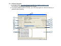
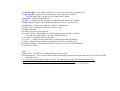
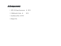
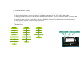
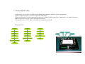
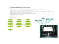
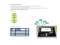
INSTRUCTION GUIDE
Gang Programmer
MTI-100u (USB Type)
MTI-100 (Parallel Type)
Release Date : 08.Jul.2014
Table of Contents
1.
Introduction
2.
Connection & Block Diagram
3.
Remote Mode (PC Control Mode)
4.
Stand-Alone Mode
5.
System Upgrade
6.
Socket Board
7.
Comparison of MTI-100u and MTI-100
8.
Components
9.
Manufacture’s warning
10. Troubleshooting
1.Introduction
The gang programmer is a tool designed for programming up to 8,10,12 flash
microcontroller of various manufacture.
It runs in either remote or standalone mode.
In Remote Mode, the gang programmer is connected to a PC through
USB or parallel port with attached cable.
In this mode, the programmer read the Intel .hex or Binary object code format,
and then program to Internal Memory and Master Socket MCU.
In Stand-alone Mode, the microcontroller can be programmed by simple key
operation directly.
Led Status : blanking Program / Verify / UpLoad Progressing
After Operation Led Status : success (Green) , error (Off).
2. Connection & Block Diagram
Host PC
USB(MTI-100u)
Master 1
Slave 7
LCD
Display
Slave 2
Slave 8
Slave 3
Slave 9
Start
Button
Menu
Button
Slave 4
Slave 10
Slave 5
Slave 11
Slave 6
Slave 12
Gang Programmer
MTI-100u/100
Parallel Port(MTI-100)
USB
//
25Pin
Parallel
Port
Power
110/220
VAC
3.Remote Mode (PC)
3-1. Software Installation
In remote mode, the gang programmer is connected to a PC through USB or
parallel port. And the gang programmer includes with CD-ROM that contains
software installation files.
To install this software, follow these steps.
1)Insert the CD-ROM into your computer system.
2)Make folder for these files on your PC. (ex. C:\Gang)
3)Copy all files to above folder.
4)Run “gangwriter.exe”
** MTI-100 Parallel Type Note :
For Windows95/98/Me the execution file will work directly,
however for Windows NT/2000/XP, you have to install
the communication driver file and reboot ,
and then run “gangwriter.exe”.
3-2. Software Operation
1. In
remote mode, you should insert the MCU to master socket or port.
the software operation is explained as follows:
2. To program Master MCU correctly, you should program to internal memory in
advance after load file.
9
1
2
3
10
11
4
12
5
13
6
14
7
8
15
1) Load File (Hex) : This button read the PC execution file (Intel Hex, program code).
2) Auto Program : Master MCU Auto Program button operates as follows.
- Writing Master MCU ROM Verify Master MCU ROM
3) Program : Program to Master MCU
4) Verify : Compare the data between PC loaded file and Master MCU ROM.
5) Read : Read the Master MCU ROM and display the data at window no.8.
6) Manufacture : Selection for Memory or MCU’s manufacture.
7) Device Type : Selection for Memory or MCU’s type.
8) Display Hex Data.
9) window page for System Upgrade.
10) Auto Program : Internal Memory Auto Program button operates as follows.
- Writing to Internal Memory Verify Internal Memory
11) Program : Program to Internal Memory.
12) Verify : Compare the data between PC loaded file and Internal Memory.
13) Read : Read the Internal Memory and display the data to window no.15.
14) External Memory : Selection for Monitor Control MCU External Flash Memory.
15) Display Hex Data.
<Note>
1.Master MCU : This MCU is inserted in Master Socket or Port.
2. Internal Memory : This is located in the equipment and this programmer read this data and write to all socket MCU
and flash memory.
3. To use the gang programmer for the first time, you should down load to this internal memory first.
4. After down load to this Internal Memory, you should Power off and on.
5. To program Master MCU, you should program Internal Memory in advance after load file.
4. Stand – Alone Mode
In stand-alone mode, you should insert at least 2 pieces MCU including master socket.
the gang programmer operate the program , verify and UpLoad function without PC system.
1)Start Button
Execute the program , verify and upload and so on.
Before press this button, you should verify the selection of menu.
2)Menu Button
This button is used for selection of menu. After this button setting, you must power On/Off.
In order to execute this button, press button at least for 3seconds continuously.
<Menu loop>
1>Pro + Ver : Program and Verify
2>Program : Program
3>Verify : Verify
4>UpLoad : Read back from master MCU to Internal Memory
This is used for loading data from master MCU ROM area and writing to Internal Memory area.
After uploading, please verify the CheckSum value.
Before you use the upload function, you should confirm the MCU Type between LCD display and
master MCU, Otherwise Upload data will be corrupted.
If you have many kind of model for ROM code, you could use this function easily.
- UpLoad Order : MCU Chg (Mem.Chg) UpLoad Pro + Ver Power off/On Start Button
5>MCU Chg : Microcontroller change
*** Note : When you use program for mass production, you must set “Pro + Ver” mode,
otherwise the ROM data could not program because of MCU boot ROM.
5. System Upgrade
System Upgrade will be needed when
the new device release or software
function upgraded.
< Upgrade Method>
1.
Connect the USB or parallel cable
between Gang Programmer and PC
system.
2.
Power on the gang programmer.
3.
Load file1,file2 and file3 at correct
position.
4.
5.
Press the System Upgrade button.
After System Upgrade, you must
power off/on the gang programmer.
Warning : Don’t mis-load file for file1, file2, file3 .
6.Socket Board
1. Socket Board design will be changed by MCU or flash memory type.
2. Regarding to DSUB Socket Board
<Specification>
- Power supply with DC Jack +5V
- Power supply from DSUB Board’s No.9 pin
- DSUB #5,#6,#7,#8,#11 pins are connected to GND pattern.
3. DSUB Socket Board 구성
Master 1
Slave 2
Slave 3
Slave 4
Slave 8
Slave 5
Slave 7
Slave 6
DC Jack
4. Refer to Manufacture’s Warning.
7.Comparison of MTI-100u and MTI-100
Model
Communication
Port
Port Number
Support Mfg.
MTI-100u
USB
10 ~ 12 EA
ADSemi, Coreriver,
Mstar, Radippulse,
Weltrend,
Semisens,Novatek
MTI-100
Parallel
10 EA
ADSemi, Coreriver,
Weltrend,
Mstar, Samsung, ST,
Toshiba
8.Components
1. MTI-100 Gang Programmer 1PCS
2. USB(Parallel) Cable 3. Installation Disk 1PCS
4. Manual File
1PCS
9.Manufacture’s Warning
1. CORERIVER(MTI-100u/MTI-100)
1) After power on, you have to check the CheckSum Data, otherwise the MCU will be fault product
2) After complete program, you have to check the EndAddress Data, otherwise the MCU will be fault product.
3) Gang programmer person always can check the CheckSum and EndAddress, so make chart for all model’s CheckSum and
EndAddress.
4) The specification of 10(12) port external 4pin connector is SMW250-4Pin Angle Type. Manufacture is Yeonho Electronics.
5) Refer to picture as below for 4Pin pin-map external port.
6) MCU Chg(change) and Upload function doesn’t use at this Coreriver version.
* Coreriver IC Memory Size & CheckSum Address
Device
Type
MemorySize
(Last Address)
CheckSum Address
TC32
8KByte (0x1FFF)
0x1FDF
TC32M
16KByte(0x3FFF)
0x1FDF (0x3FFF)
TC32n
16KByte(0x3FFF)
0x1FDF (0x3FFF)
TC34n_1
31.7KByte(0x7BFF)
0x7BFF
TC370
32KByte(0x7FFF)
0x7FFF
TC350
8KByte(0x1FFF)
0x1FFF
Model Information
<TC3xxK Series>
1.TC3xxK (IC Size : 0x3FFF(16KByte))
<TC32 Series>
1.TC32 (IC Size : 0x1FFF(8KByte)) The checksum doesn't count last 32byte.
2.TC32M (IC Size : 0x3FFF(16KByte)) has show checksum (Max. 0x1FCF)
3.TC32n (IC Size : 0x3FFF(16KByte)) has show checksum (Max. 0x1FCF)
4.TC34n_1 (IC Size : 0x7BFF(31KByte))
5.TC30Q (IC Size : 0xFFFF(64KByte))
6.TC300S (IC Size : 0x7FFF(32KByte))
<TC350 Series>
1.TC350 (IC Size : 0x1FFF(8KByte))
2.TC370 (IC Size : 0x7FFF(32KByte))
3.TC380 (IC Size : 0x3FFF(16KByte))
4.TC390 (IC Size : 0x7FFF(32KByte))
Data
GND
Vcc
Clock
1-1. CORERIVER2(MTI-100u/MTI-100)
1) Coreriver2’s all operation is the same as conventional Coreriver.
2) Coreriver2’s upper socket board is different from the conventional Coreriver. [4pin 5pin connector], [Add Vpp High Voltage Supply line ]
3) When program ATOM120, Use 5pin connector.
4) When program ATOM120, 1K,2K,4K BYTE program mode is fixed, when you setting the device type..
5) When program ATOM120, Press Verify button on PC , you can see the CFGWD Data of current IC connected master port.
6) The specification of 12 port external 5pin connector is SMW250-5Pin Angle Type. Manufacture is Yeonho Electronics.
7) Refer to picture as below for 5Pin pin-map external port.
8) MCU Chg(change) and Upload function doesn’t use at this Coreriver2 version.
Data
* Coreriver IC Memory Size
Device
Type
MemorySize
(Last Address)
ATOM120
1K,2K,4KByte(0xFFF)
ATOM130
1K,2K,4KByte(0xFFF)
GND
Vcc
Clock
Vpp(+7.5V)
2. CYPRESS(MTI-100u)
1) After power on, you have to check the CheckSum Data, otherwise the MCU will be fault product
2) After complete program, you have to check the EndAddress Data, otherwise the MCU will be fault product.
3) Gang programmer person always can check the CheckSum and EndAddress, so make chart for all model’s CheckSum and
EndAddress.
4) The specification of 10 port external 4pin connector is SMW250-4Pin Angle Type. Manufacture is Yeonho Electronics.
5) Refer to picture as below for 4Pin pin-map external port.
6) MCU Chg(change) and Upload function doesn’t use at this Coreriver version.
7)Program Flow
Pro+Ver
Program
Verify
Mode Start
Mode Start
Mode Start
Verify IC type
Verify IC type
Verify IC type
Program
Program
Verify IC checksum
Verify all address
Verify IC checksum
Stop
Verify IC checksum
Program Protect On
Program Protect On
Stop
Stop
Data
GND
Vcc
Clock
3. Weltrend(MTI-100)
1) After power on, you have to check the CheckSum Data, otherwise the MCU will be fault product
2) After complete program, you have to check the LED status.
3) The specification of 10 port external 4pin connector is SMW250-4Pin Angle Type. Manufacture is Yeonho Electronics.
4) Refer to picture as below for 4Pin pin-map external port.
5) External Power is +3.3V. This is used only for external target PCB IC.
6)Program Flow
Pro+Ver
Program
Verify
Mode Start
Mode Start
Mode Start
Erase IC
Erase IC
Verify
Program
Program
Reset
Verify
Program End & Reset
Stop
Program End & Reset
Stop
GND
Stop
Data
Vcc
Clock
4. ADSemiconductor(MTI-100/MTI-100u)
1) After power on, you have to check the CheckSum Data, otherwise the MCU will be fault product
2) After complete program, you have to check the LED status.
3) The specification of 10 port external 4pin connector is SMW250-5Pin Angle Type. Manufacture is Yeonho Electronics.
4) Refer to picture as below for 5Pin pin-map external port.
5) External Power is +12V. This is used only for external target PCB IC.
6) Program under no.5 OTP space.
7)Program Flow
Vcc
Pro+Ver
Program
Clock
Verify
Data
Mode Start
Mode Start
Mode Start
Program
Program
Reset
Reset
Program End
Verify
Verify
Stop
Stop
Stop
GND
+12V
5. Radiopulse(MTI-100u)
1) After power on, you have to check the CheckSum Data, otherwise the MCU will be fault product
2) After complete program, you have to check the LED status.
3) The specification of 12 port external 5pin connector is SMW250-5Pin Angle Type. Manufacture is Yeonho Electronics.
4) Refer to picture as below for 5Pin pin-map external port.
5) Connect between Radiopulse IC’s ISP pin and Vcc(+3.3V) line.
6) When it use under 12 port, connect the port clock wise.
7) The GangWriter.exe’s folder must have the \DataBase\Mti-100u_logfile.txt. After PC program execute, you can run the MTI-100u.
8) In order to modify the IEEE Address and Manufacture Code, you can change at a last line of MTI-100u_logfile.txt.
9)Program Flow
Pro+Ver
Vcc & ISP pin
Mode Start
GND
Program
Txd
Verify
Program End
Stop
Rxd
Reset
5. Semisens(MTI-100u)
1) After power on, you have to check the CheckSum Data, otherwise the MCU will be fault product
2) After complete program, you have to check the LED status.
3) The specification of 12 port external 5pin connector is SMW250-5Pin Angle Type. Manufacture is Yeonho Electronics.
4) Refer to picture as below for 5Pin pin-map external port.
5) When it use under 12 port, connect the port clock wise.
6)Program Flow
Pro+Ver
Mode Start
Program
Verify
Vcc
Program End
GND
Stop
Clock
Reset
Data
* Semisens IC Memory Size
Device
Type
MemorySize
(Last Address)
SN240
16KByte (0x3FFF)
Semisens Ver.1.00
10.Trouble Shooting
1. Unable to communicate for USB
-Solution
1)Power On the MTI-100u.
2)Connect the USB Cable between PC and MTI-100u.
3)Operate the Dip S/W as follows:
< No.1 On No.2 On No.2 Off No.1 Off >
4)Execute the “Gangwriter.exe” .
5)Move to System Manager page, load file1, file2, file3 and then press button the “System Upgrade”.
6)After system upgrade, you must do power Off/On and execute “Gangwriter.exe” again.
2. Parallel Port communication Driver Installation method And
Frequently when the data communication error occur at Windows XP,2000,NT,Vista,Win7.
-root cause
1)Windows’ Printer Port Driver interfere the I2C communication..
-Solution
1)Update Driver from Parallel Port Driver(LPT1) to ‘MasTech I2c Communication Driver2’.
Desktop MyComputer ClickRightMouse Properties Harware Equipment Manager Port ECP PrinterPort(LPT1) ClickRightMouse Properties Drivers Update Driver
No, now no connect, 목록 또는 특정 위치에서 설치 검색 안함, 설치할 드라이브를 직접 선택
Disk Search winDDC Folder (MTPARISP.inf) .
Press button install the driver with OK, NEXT.
Use after reboot.
3.To recover original parallel port operation
- Solution
1)Desktop MyComputer ClickRightMouse Properties Hardware Equipment Manager Port MasTech I2c Communication Driver(LPT1) ClickRightMouse Properties Driver Rollback Driver