1
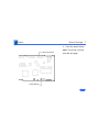
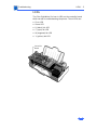
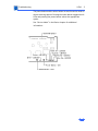
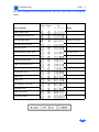
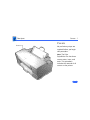
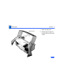
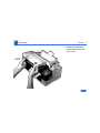
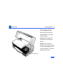
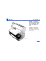
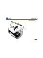
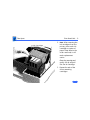
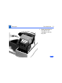
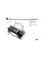
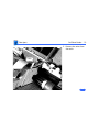
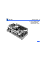
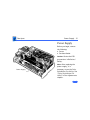
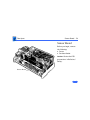
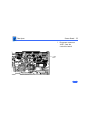
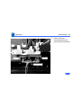
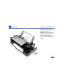
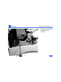
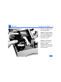
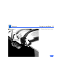
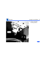
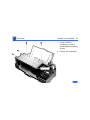
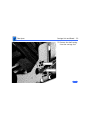
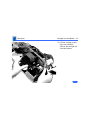
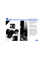
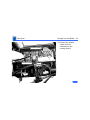
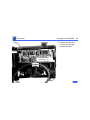
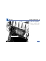
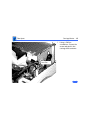
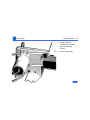
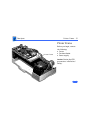
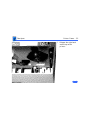
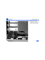
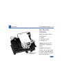
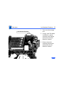
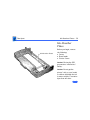
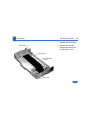
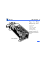
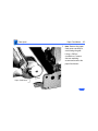
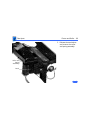
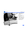
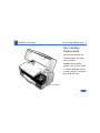
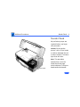
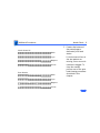
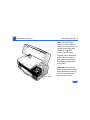
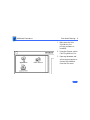
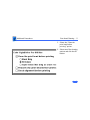
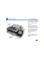
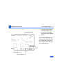
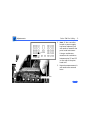
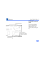
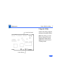
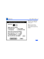
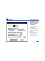
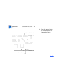
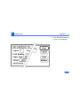
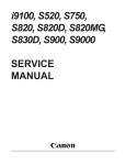
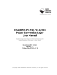
K Service Source
Color StyleWriter Pro
K Service Source
Basics
Color StyleWriter Pro
Basics
Overview - 1
Overview
The Color StyleWriter Pro
is a desktop color bubblejet printer for personal use.
It has various features such
as high-speed printing, high
print quality, printing on
plain paper, and a cut sheet
feeder.
The user can easily replace
the print head (64 nozzles,
four colors) and ink
cartridges (each color has a
separate cartridge).
Basics
Overview - 2
The Color StyleWriter Pro
has six LEDs on the
controller board which can
aid in troubleshooting the
printer. See the
Troubleshooting chapter for
more information.
Controller
Board
LEDs
Basics
Service Mode - 3
Controller
Board
Buttons and LEDs
Service Mode
Note: This procedure uses
the buttons and LEDs on the
controller board to perform
service functions, i.e., test
pages.
Note: You must remove the
top cover and the inner
cover to access the
controller board. See
“Covers” in the Take Apart
chapter.
Basics
Service Mode - 4
Controller Board
Hold down the power and
select buttons and plug in
the printer power cord.
Note: The printer will emit
a four-tone beep indicating
that it is in the service
mode.
See the “Color StyleWriter
Pro Utility” and
“Alignment” in the
Adjustments chapter for
additional information.
Select Button
Power Button
Basics
Service Test Page - 5
Service Test Page
Note: This procedure
explains how to print the
service test page, which
indicates if the print heads
need to be aligned. You must
be in service mode to print a
service test page.
1
2
Print Heads
Place paper in the cut
sheet feeder.
Place printer in service
mode. See “Service
Mode” in this chapter.
Basics
Service Test Page - 6
3
Controller Board
Black LED (LED 5)
Magenta LED (LED 3)
Yellow LED (LED 2)
Select Button
Press the select button
until the black (LED 5),
magenta (LED 3), and
yellow (LED 2) LEDs
light up.
Basics
Service Test Page - 7
4
Controller Board
Power Button
Press the power button.
Note: The printer will now
print the test page.
K Service Source
Specifications
Color StyleWriter Pro
Specifications
Characteristics - 1
Characteristics
Print Methods
Serial bubble jet ink-on-demand
Throughput
170 cps (10 cpi)
240 cps (10 cpi)
Print Head
1 x 64 nozzles for each color
Print Head Life
Thousands of pages
Input Buffer
60 KB
text/standard speed mode
text/high speed mode
Specifications
Graphics - 2
Graphics
Resolution
360 dpi (best mode)
180 dpi (draft mode)
Specifications
Paper Handling - 3
Paper Handling
Paper
Cut Sheets
Envelopes
Plain paper, coated (recommended for color picture output)
LTR, LGL, A4
U.S. Letter (LTR): 8.5 x 11 in. (215.9 mm x 279.4 mm)
U.S. Legal (LGL) : 8.5 x 14 in. (215.9 mm x 355.6 mm)
A4: 210 mm x 297 mm
Weight: 16–24 lbs. Capacity: 100 sheets (A4, LTR)
Commercial number 10, monarch, and other sizes
Capacity: 15 envelopes
Specifications
Transparencies
Back-Print Film
Paper Handling - 4
Coated transparencies, most ink jet transparencies
Letter, A4
For superior graphics and imaging results, premium paper and
back-print film are recommended
Specifications
Ink Cartridges - 5
Ink Cartridges
Type
Color ink cartridges (four available)
Ink Color
Black, cyan, magenta, yellow
Ink Amount
Approx. 8 g (per cartridge)
Shelf Life
6 months (installed in printer)
18 months (in original package)
Cartridge Life
Text: Approx. 315 pages (A4/LTR) at 5% coverage per color
Specifications
Environmental - 6
Environmental
Acoustic Noise Level
Approx. 45 dB (reference level)
Temperature
59–86°F (15–30°C)
Humidity
10–80% (no condensation)
Specifications
Electrical - 7
Electrical
Electrical
Requirements
120 V, 60 Hz, 1 amp
220–240 V, 50 Hz, 0.5 amp
Power Consumption
28 W maximum
Specifications
Physical - 8
Physical
Dimensions
Weight
Height: 7.2 in. (184 mm)
Width: 16.5 in. (418 mm)
Depth: 10.1 in. (256 mm)
Approx. 11 lbs. (5 kg)
K Service Source
Troubleshooting
Color StyleWriter Pro
Troubleshooting
General/ - 1
General
The Symptom Charts included in this chapter will help you
diagnose specific symptoms related to your product. Because cures
are listed on the charts in the order of most likely solution, try
the first cure first. Verify whether or not the product continues to
exhibit the symptom. If the symptom persists, try the next cure.
(Note: If you have replaced a module, reinstall the original module
before you proceed to the next cure.)
If you are not sure what the problem is, or if the Symptom Charts
do not resolve the problem, refer to the Flowchart for the product
family.
For additional assistance, contact Apple Technical Support.
Troubleshooting
LEDs/ - 2
LEDs
The Color StyleWriter Pro has six LEDs on the controller board
which can aid in troubleshooting the printer. The six LEDs are:
• Error LED
• Power LED
• K (black) Ink LED
• C (cyan) Ink LED
• M (magenta) Ink LED
• Y (yellow) Ink LED
Controller
Board
LEDs
Troubleshooting
LEDs/ - 3
The power button and the select button are used in service mode to
choose servicing options. Pressing the select button toggles the ink
LEDs and pressing the power button selects the appropriate
option.
See “Service Mode” in the Basics chapter for additional
information.
Troubleshooting
LEDs/ - 4
The LEDs indicate the state of the printer or whether an error has occurred (e.g., carriage
control error, paper jam).
The following charts provide a summary of printer states and error codes.
Printer State
LED Indication Summary
Power LED
Error
6
LEDs
Power
Ink
1
5 4 3 2
Notes
Error
6
LEDs
Power
Ink
1
5 4 3 2
Notes
Power off
Power on
Transition of power on/off
Printer State
LED Indication Summary
Ink LED
Normal condition
Power on
Error in other than print head
Affected LED is on
Error in print head
Affected LED blinks
Printer State
Normal LED Indication
In Service Mode
Error
6
LEDs
Power
Ink
1
5 4 3 2
Notes
Entering service mode
Emits four-tone chord
EEPROM download mode
Affected LED is on
Initial cleaning
Affected LED blinks
Service Test Page
Troubleshooting
LEDs/ - 5
If an error is indicated, check the following chart, then go to “Error LEDs” in the Symptom
Charts.
Error Indication
Error
6
LEDs
Power
Ink
1
5 4 3 2
Notes
Paper empty/jam
Ink absorber plate error
Ink cartridge empty
Empty color blinks
Carriage control error
Recovery error
Home position sensor error
Linear encoder error
Cleaner sensor error
Paper feed motor error
Cut sheet feeder sensor error
Thermistor error
ROM error
RAM error
Ink absorber full error
EEPROM error
Gate array error
Print head error
Carriage sensor
Troubleshooting
Symptom Charts/Operation - 6
Symptom Charts
Operation
No power
1
2
3
4
Check power cable connections.
Replace power cord.
Replace fuse.
Replace power supply.
Does not print
1
2
3
Turn on printer and restart computer.
Check interface cable connections.
Replace printer driver.
Printer takes long
time to initialize at
first startup
Printer normally takes 5–7 minutes to prepare print head at
first startup.
Troubleshooting
Symptom Charts/Paper - 7
Paper
Paper sticks together
1
2
3
4
Remove excess sheets from paper tray.
Use specified media only.
Check that settings in Page Setup menu are correct.
Fan paper before putting in paper tray.
Paper skews
1
2
3
Remove excess sheets from paper tray.
Use specified media only.
Stack paper flush against left side of paper tray and adjust
paper guide.
Check rollers. Clean or replace if necessary.
4
Paper jams during
loading, before
printing
Carefully remove paper by hand.
Troubleshooting
Symptom Charts/Paper (Continued) - 8
Paper (Continued)
Paper jams inside
printer
Pull out paper in direction of paper output. (Do not pull paper
back toward you.)
Paper jams during
output, after printing
Pull out paper in direction of paper output.
Troubleshooting
Symptom Charts/Print Quality - 9
Print Quality
Missing dots and/or
white streaks
1
2
3
4
5
6
Blurring and/or
smudging
1
2
3
4
Perform “Nozzle Check” and “Print Head Cleaning”. See
Additional Procedures chapter.
Make sure ink cartridges are set firmly.
Use specified media only.
Replace print head unit.
Replace carriage board. Run the Color StyleWriter Pro
Utility (see Adjustments chapter).
Replace controller board. Run the Color StyleWriter Pro
Utility (see Adjustments chapter).
Adjust print head position lever all the way down.
Use specified media only.
Make sure print head is in correct position. If necessary,
perform “Alignment”. See Adjustments chapter.
Perform “Print Head Cleaning.” See Additional Procedures
chapter.
Troubleshooting
Symptom Charts/Error LEDs - 10
Error LEDs
Paper jam/error
1
2
3
4
5
6
Ink cartridge empty
1
2
3
4
5
Pull out paper in direction of paper output.
Use specified media only.
Stack paper flush against left side of paper tray and adjust
paper guide.
Check rollers. Clean or replace if necessary.
Check for foreign objects in paper path.
Replace controller board. Run the Color StyleWriter Pro
Utility (see Adjustments chapter).
Replace ink cartridge.
Perform “Print Head Cleaning.” See Additional Procedures
chapter.
Perform “Print Head Purging.” See Additional Procedures
chapter
Replace purge unit.
Replace controller board. Run the Color StyleWriter Pro
Utility (see Adjustments chapter).
Troubleshooting
Symptom Charts/Error LEDs (Continued) - 11
Error LEDs (Continued)
Carriage control
error
1
2
3
4
5
6
Check carriage unit path for obstructions.
Replace carriage motor.
Replace linear encoder.
Replace home position sensor.
Replace carriage ribbon cable.
Replace controller board. Run the Color StyleWriter Pro
Utility (see Adjustments chapter).
Carriage home
position sensor error
1
2
3
4
5
6
Check carriage unit path for obstructions.
Replace carriage motor.
Replace linear encoder.
Replace home position sensor.
Replace carriage ribbon cable.
Replace controller board. Run the Color StyleWriter Pro
Utility (see Adjustments chapter).
Troubleshooting
Symptom Charts/Error LEDs (Continued) - 12
Error LEDs (Continued)
Linear encoder error
1
2
3
Make sure linear encoder is installed in correct orientation.
Replace linear encoder.
Replace controller board. Run the Color StyleWriter Pro
Utility (see Adjustments chapter).
Cleaner sensor error
1
2
3
Replace purge unit.
Replace carriage unit.
Replace controller board. Run the Color StyleWriter Pro
Utility (see Adjustments chapter).
Paper feed motor
error
1
2
Replace paper feed motor.
Replace controller board. Run the Color StyleWriter Pro
Utility (see Adjustments chapter).
Ink absorber plate
error
Replace the ink absorber plates. Run the Color StyleWriter Pro
Utility (see Adjustments chapter).
Troubleshooting
Symptom Charts/Error LEDs (Continued) - 13
Error LEDs (Continued)
Cut sheet feeder
sensor error
1
2
3
4
5
Thermistor error
1
2
Check paper feed path for obstructions.
Check that scale holder and shaft spring at both sides of
carriage are holding carriage assembly properly. See
“Carriage Unit and Board” in Take Apart chapter.
Check bushing on left side of printer frame. If it is damaged
or missing, replace it. The platen and roller assembly will
not be seated properly without the bushing. See “Platen and
Roller” in Take Apart chapter.
Replace cut sheet feeder.
Replace controller board. Run the Color StyleWriter Pro
Utility (see Adjustments chapter).
Replace carriage ribbon cable.
Replace carriage board. Run the Color StyleWriter Pro
Utility (see Adjustments chapter).
Troubleshooting
Symptom Charts/Error LEDs (Continued) - 14
Error LEDs (Continued)
ROM error
Replace controller board. Run the Color StyleWriter Pro Utility
(see Adjustments chapter).
RAM error
Replace controller board. Run the Color StyleWriter Pro Utility
(see Adjustments chapter).
EEPROM error
Replace controller board. Run the Color StyleWriter Pro Utility
(see Adjustments chapter).
Gate array error
Replace controller board. Run the Color StyleWriter Pro Utility
(see Adjustments chapter).
Troubleshooting
Symptom Charts/Error LEDs (Continued) - 15
Error LEDs (Continued)
Print head error
1
2
3
4
5
Make sure the print head cover is fastened down securely.
Perform “Print Head Cleaning.” See Additional Procedures
chapter.
Replace print head.
Replace carriage ribbon cable.
Replace carriage board. Run the Color StyleWriter Pro
Utility (see Adjustments chapter).
Ink absorber plate
full error
Replace the ink absorber plates. Run the Color StyleWriter Pro
Utility (see Adjustments chapter).
Recovery error
Check the paper feed clutch on the right side of the platen. Verify
it is in the correct position.
K Service Source
Take Apart
Color StyleWriter Pro
Take Apart
Covers
Covers - 1
Covers
No preliminary steps are
required before you begin
this procedure.
Note: The Color
StyleWriter Pro has three
covers–outer, inner, and
main. This procedure
includes the removal of all
covers on the printer.
Take Apart
Covers - 2
Top Cover
Hinge
Hinge
1
2
Raise the top cover.
Gently press in the two
hinges and lift off the top
cover.
Take Apart
Covers - 3
3
Front
Latches
Release the two front
latches and remove the
inner cover.
Take Apart
Covers - 4
4
Release the mounting
latches.
Take Apart
Covers - 5
5
6
7
Rear
Latches
Lay the printer on the
front side.
Release the rear latches
and remove the main
cover.
Stand the printer
upright.
Take Apart
Print Head Unit - 6
Print Head Unit
No preliminary steps are
required before you begin
this procedure.
Caution: Review the ESD
precautions in Bulletins/
Safety.
Caution: Do not get the
printer’s ink on your hands
or clothes. Although the ink
is water soluble, it contains
dyes that will stain.
Print Head Unit
Take Apart
Print Head Unit - 7
Caution: To prevent the
print nozzles from clogging,
do not touch or wipe them
when removing the print
head.
Caution: Do not leave the
print heads uncapped for
more than 12 hours or they
will dry out.
Print Head Unit
Take Apart
Print Head Unit - 8
1
Top
Cover
Open the top cover.
Take Apart
Print Head Unit - 9
Ink Cartridges
2
3
Note: After removing the
ink cartridges from the
printer, place each ink
cartridge on a piece of
paper. Keep them in the
order removed; it will
make replacement
easier.
Grasp the top edge and
gently lift up and pull
out the ink cartridge.
Repeat for each of the
three remaining
cartridges.
Take Apart
Print Head Unit - 10
Ink Cartridges
4
Replacement Note: Do
not shake the ink
cartridges or the ink
may leak.
Take Apart
Print Head Unit - 11
5
Print Head Cover
Push in both latches and
open the print head
cover.
Replacement Note:
When closing the print
head cover, press firmly
until you hear two clicks
and the cover will not go
down further. The cover
should be completely
horizontal. Failure to
close the print head
cover properly will
cause print head failure.
Take Apart
Print Head Unit - 12
6
7
Print Head
Print Nozzles
Note: To prevent the
print nozzles from
clogging, do not touch or
wipe them.
Grasp the print head and
gently remove it from
the printer.
Place the print head on a
piece of paper.
Replacement Note:
Before installing a new
print head, remove the
tape that covers the
print nozzles.
Take Apart
Controller Board - 13
Controller Board
Controller
Board
Before you begin, remove
the covers.
Caution: Review the ESD
precautions in Bulletins/
Safety.
Note: After replacing the
controller board, it is
necessary to run the Color
StyleWriter Pro Utility. See
“Color StyleWriter Pro
Utility” in the Adjustments
chapter.
Take Apart
Controller Board - 14
1
Disconnect the following
connectors from the
controller board:
• LFM1
• JPOW1
• JCRM1
• JHPS1
• JPGS1
• JPGM1
• JAFS1
Take Apart
Controller Board - 15
2
Disconnect the following
ribbon cables from the
controller board:
• JCR1
• JCR2
Take Apart
Controller Board - 16
3
4
Controller
Board
Using a Phillips
screwdriver, remove
the four mounting
screws.
Remove the controller
board.
Take Apart
Cut Sheet Feeder - 17
Cut Sheet Feeder
Cut Sheet Feeder
Before you begin, remove
the covers.
Caution: Review the ESD
precautions in Bulletins/
Safety.
Take Apart
Cut Sheet Feeder - 18
1
Using a Phillips
screwdriver, remove
the two mounting
screws.
Take Apart
Cut Sheet Feeder - 19
2
Catch
Remove the wires from
the catch.
Take Apart
Cut Sheet Feeder - 20
3
Latch
Latch
Press in the two latches
and remove the sheet
feeder from the printer.
Take Apart
Power Supply - 21
Power Supply
Before you begin, remove
the following:
• Covers
• Cut sheet feeder
Caution: Review the ESD
precautions in Bulletins/
Safety.
Power Supply
Note: After replacing the
power supply, it is
necessary to run the Color
StyleWriter Pro Utility. See
“Color StyleWriter Pro
Utility” in the Adjustments
chapter.
Take Apart
Power Supply - 22
1
2
Holding Tabs
Disconnect connector
JPOW1 from the
controller board.
Release the wires from
the holding tabs.
Take Apart
Power Supply - 23
3
Power Supply
Using a Phillips
screwdriver, loosen the
two mounting screws and
remove the power
supply.
Take Apart
Sensor Board - 24
Sensor Board
Before you begin, remove
the following:
• Covers
• Cut sheet feeder
Caution: Review the ESD
precautions in Bulletins/
Safety.
Sensor Board
Take Apart
Sensor Board - 25
1
Disconnect connector
JASF1 from the
controller board.
Take Apart
Sensor Board - 26
2
Latch
Latch
Sensor Board
Push out the two
mounting latches and
remove the sensor board.
Take Apart
Carriage Unit and Board - 27
Carriage Unit and
Board
Before you begin, remove
the following:
• Covers
• Controller board
Caution: Review the ESD
precautions in Bulletins/
Safety.
Carriage
Unit and
Board
Caution: Do not use a
magnetized screwdriver
near the encoder. A
magnetized screwdriver
will damage the encoder.
Take Apart
Carriage Unit and Board - 28
Note: After replacing the
carriage board, it is
necessary to run the Color
StyleWriter Pro Utility. See
“Color StyleWriter Pro
Utility” in the Adjustments
chapter.
Carriage
Unit and
Board
Take Apart
Carriage Unit and Board - 29
Carriage Unit
1
Advance the locking gear
and disengage the
carriage.
Take Apart
Carriage Unit and Board - 30
2
Move the carriage out of
the home position.
Caution: The print heads
are now uncapped. Do not
leave them uncapped for
more than 12 hours or
they will dry out.
Carriage Unit
Print Heads
Caution: Do not get the
printer’s ink on your
hands or clothes.
Although the ink is water
soluble, it contains dyes
that will stain.
Take Apart
Carriage Unit and Board - 31
3
Carriage Belt
Tensioner
Using a Phillips
screwdriver, loosen the
screw and push in the
carriage belt tensioner.
Take Apart
Carriage Unit and Board - 32
4
Carriage Belt
Remove the carriage
belt.
Take Apart
Carriage Unit and Board - 33
5
Ferrite Core
Remove the ferrite core.
Take Apart
Carriage Unit and Board - 34
6
Mounting
Bracket
Remove the plastic
mounting bracket.
Take Apart
Carriage Unit and Board - 35
7
8
Shield Plate
Using a Phillips
screwdriver, remove
the shield plate mounting
screws.
Remove the shield plate.
Take Apart
Carriage Unit and Board - 36
9
Carriage Unit
Carriage Rod
Pull up the front of the
carriage unit and release
it from the front
carriage rod.
Take Apart
Carriage Unit and Board - 37
10 Remove the scale spring.
Scale Spring
Take Apart
Carriage Unit and Board - 38
11 Press in the latches and
remove the scale holder
from the printer.
Scale Holder
Take Apart
Carriage Unit and Board - 39
12 Remove the shaft spring
from the carriage rod.
Shaft Spring
Carriage Rod
Take Apart
Carriage Unit and Board - 40
13 Pull the carriage to the
right and carefully
remove the carriage rod
from the chassis.
Carriage Unit
Take Apart
Carriage Unit and Board - 41
14 Caution: Be careful not
to bend the encoder
when removing it from
the chassis.
Carefully remove the
encoder and carriage
unit from the printer.
Encoder
Replacement Note: Make
sure the encoder is
installed in the proper
orientation in the scale
holder. Failure to do so
will cause an encoder
error to develop.
Take Apart
Carriage Unit and Board - 42
15 Caution: Be careful not
to bend the encoder.
Carefully place the
carriage unit in front of
the printer.
Encoder
Carriage
Unit
Take Apart
Carriage Unit and Board - 43
Flexible Cable
Flexible Cable
16 Remove the flexible
cables from the
connectors on the
carriage board.
Take Apart
Carriage Unit and Board - 44
17 Release the latch and
remove the carriage
board and shield.
Latch
Carriage Board
and Shield
Take Apart
Carriage Unit and Board - 45
18 Remove the carriage belt
holder and belt.
Carriage Belt Holder
Carriage Belt
Take Apart
Carriage Unit and Board - 46
19 Open the carriage unit.
20 Remove the ribbon cable
holder and ribbon cable.
Ribbon Cable
Ribbon Cable Holder
Take Apart
Carriage Motor - 47
Carriage Motor
Before you begin, remove
the covers.
Caution: Review the ESD
precautions in Bulletins/
Safety.
Carriage
Motor
Take Apart
Carriage Motor - 48
1
Carriage Belt
Tensioner
Using a Phillips
screwdriver, loosen the
screw and push in the
carriage belt tensioner.
Take Apart
Carriage Motor - 49
2
3
JCRM1
Mounting
Bracket
Disconnect connector
JCRM1 from the
controller board.
Remove the wires from
the mounting bracket.
Take Apart
Carriage Motor - 50
4
Mounting Screw
Mounting Screw
5
Using a Phillips
screwdriver, remove
the two mounting
screws.
Remove the motor.
Take Apart
Printer Frame - 51
Printer Frame
Printer Frame
Before you begin, remove
the following:
• Covers
• Cut sheet feeder
• Power supply
Caution: Review the ESD
precautions in Bulletins/
Safety.
Take Apart
Printer Frame - 52
1
Right Latch
Release the right latch
and lift up on the
printer.
Take Apart
Printer Frame - 53
2
Left Latch
Release the left latch
and remove the printer
frame from the printer.
Take Apart
Ink Absorber Elements - 54
Ink Absorber
Elements
Before you begin, remove
the following:
• Covers
• Controller board
• Carriage unit
Caution: Review the ESD
precautions in Bulletins/
Safety.
Ink Absorber
Elements
Caution: Do not get the
printer’s ink on your hands
or clothes. Although the ink
is water soluble, it contains
dyes that will stain.
Take Apart
Ink Absorber Elements - 55
Sub Absorber Element
1
2
3
Main Absorber Element
Turn over the carriage
unit.
Using a small flat-blade
screwdriver, gently
release the two latches
and remove the main
absorber element.
Gently release the
remaining two latches
and remove the sub
absorber element.
Take Apart
Ink Absorber Plates - 56
Ink Absorber
Plates
Ink Absorber Plates
Before you begin, remove
the following:
• Covers
• Sheet feeder
• Printer frame
Caution” Review the ESD
precautions in Bulletins/
Safety.
Caution: Do not get the
printer’s ink on your hands
or clothes. Although the ink
is water soluble, it contains
dyes that will stain.
Take Apart
Ink Absorber Plates - 57
Ink Absorber Plates
Note: After replacing the ink
absorber plates, it is
necessary to run the Color
StyleWriter Pro Utility. See
“Color StyleWriter Pro
Utility” in the Adjustments
chapter.
Take Apart
Ink Absorber Plates - 58
1
2
Side Latch
Front Latch
Ink Absorber
Cover
Side Latch
Release the front latch.
Release the two side
latches and remove the
ink absorber cover.
Take Apart
Ink Absorber Plates - 59
3
Ink Absorber
Plates
Remove the three ink
absorber plates.
Take Apart
Paper Feed Motor - 60
Paper Feed Motor
Before you begin, remove
the following:
• Covers
• Cut sheet feeder
• Power supply
• Printer frame
Caution: Review the ESD
precautions in Bulletins/
Safety.
Paper Feed Motor
Take Apart
Paper Feed Motor - 61
1
2
Mounting Bracket
Disconnect connector
JLFM1 from the
controller board.
Release the wires from
the mounting bracket.
Take Apart
Paper Feed Motor - 62
3
Note: Remove the paper
feed motor carefully to
avoid losing the gear.
Using a Phillips
screwdriver, remove
the two mounting
screws and remove the
paper feed motor.
Paper Feed Motor
Gear
Take Apart
Paper Guide - 63
Paper Guide
Before you begin, remove
the following:
• Covers
• Cut sheet feeder
• Power supply
• Printer frame
Paper Guide
Caution: Review the ESD
precautions in Bulletins/
Safety.
Take Apart
Paper Guide - 64
1
Disconnect ribbon cables
JCR1 and JCR2 from the
controller board.
Take Apart
Paper Guide - 65
2
Ferrite Core
Release the latches on
the ferrite core and
remove the core and the
ribbon cables.
Take Apart
Paper Guide - 66
3
4
Paper Guide
Push in the catch on the
left side and push down
on the paper guide.
Repeat for the right side
and remove the paper
guide.
Take Apart
Platen and Roller - 67
Platen and Roller
Before you begin, remove
the following:
• Covers
• Cut sheet feeder
• Power supply
• Printer frame
Platen and Roller
Caution: Review the ESD
precautions in Bulletins/
Safety.
Take Apart
Platen and Roller - 68
1
2
Bushing
Replacement Note: You
will need a bushing kit to
complete this procedure.
Break off the bushing
and slide the platen
assembly forward.
Carefully remove the
washer and spring and
remove the platen
assembly.
Take Apart
Platen and Roller - 69
3
Roller and
Spring
Assembly
Latch
Release the two latches
and remove the roller
and spring assembly.
Take Apart
Platen and Roller - 70
4
Gently grasp the spur
holder unit and remove
it from the roller and
spring assembly.
Take Apart
Platen and Roller - 71
5
6
Feeder Roller
Turn over the platen
assembly.
Pull up and remove the
feeder roller.
Take Apart
Photo Interrupter - 72
Photo Interrupter
Photo Interrupter
Before you begin, remove
the following:
• Covers
• Cut sheet feeder
• Carriage motor
• Power supply
• Printer frame
Caution: Review the ESD
precautions in Bulletins/
Safety.
Take Apart
Photo Interrupter - 73
1
Disconnect the home
position cable connector
JHPS1 from the
controller board.
Take Apart
Photo Interrupter - 74
2
Home Position Cable
Disconnect the home
position cable from the
photo interrupter.
Take Apart
Photo Interrupter - 75
3
4
Top Latches
Bottom Latches
Press in the two bottom
latches and pull back on
the photo interrupter.
Press in the top latches
and remove the photo
interrupter.
Take Apart
Purge Unit - 76
Purge Unit
Before you begin, remove
the following:
• Covers
• Cut sheet feeder
• Power supply
• Printer frame
Caution: Review the ESD
precautions in Bulletins/
Safety.
Purge Unit
Take Apart
Purge Unit - 77
1
2
Disconnect connectors
JPGS1 and JPGM1 from
the controller board.
Remove the wires from
the mounting plate.
Take Apart
Purge Unit - 78
Carriage Unit
3
4
Advance the locking gear
and disengage the
carriage.
Move the carriage out of
home position.
Caution: The print heads
are now uncapped. Do not
leave them uncapped for
more than 12 hours or
they will dry out.
Take Apart
Purge Unit - 79
5
6
White Lever
Purge Unit
Using a Phillips
screwdriver, remove
the mounting screw.
Remove the purge unit.
Replacement Note: Make
sure the white lever
from the platen
assembly is in the
position shown.
K Service Source
Additional Procedures
Color StyleWriter Pro
Additional Procedures
Printer Cleaning - 1
Printer Cover
Printer Cleaning
No preliminary steps are
required before you begin
this procedure.
Caution: Do not get the
printer’s ink on your hands
or clothes. Although the ink
is water soluble, it contains
dyes that will stain.
Platen
Using a damp cloth, wipe the
ink mist off the printer
cover and platen.
Additional Procedures
Ink Cartridge Replacement - 2
Ink Cartridge
Replacement
No preliminary steps are
required before you begin
this procedure.
Caution: Do not get the
printer’s ink on your hands
or clothes. Although the ink
is water soluble, it contains
dyes that will stain.
Ink Cartridges
Additional Procedures
Ink Cartridge Replacement - 3
Ink Cartridges
Note: Do not shake the ink
cartridge or the ink may
leak.
1
Color Label
2
3
Grasp the top edge of the
used ink cartridge and
gently lift up and pull
out the cartridge.
Repeat for any other
used cartridges.
With the color label on
top, insert the new
cartridge gently into the
appropriate slot. Press
down until you hear a
click.
Additional Procedures
Nozzle Check - 4
Nozzle Check
No preliminary steps are
required before you begin
this procedure.
Caution: Do not get the
printer’s ink on your hands
or clothes. Although the ink
is water soluble, it contains
dyes that will stain.
Print Head
Note: This procedure
explains how to run the
nozzle check test page,
which indicates if the print
heads need to be cleaned.
Ê
Additional Procedures
Cut Sheet Feeder
Nozzle Check - 5
Important: Make sure the
printer is off.
1
2
Power Key
Load paper into the cut
sheet feeder.
Hold down the power key
until the printer prints
the start-up test page.
Additional Procedures
Nozzle Status OK
Nozzle Check - 6
3
Black
Cyan
Magenta
Yellow
Clean Nozzles
Black
Cyan
Magenta
Yellow
Examine the bottom of
the printed page to
determine print head
status.
If the horizontal lines in
the test pattern are
missing, one or more ink
nozzles are clogged. To
clear the nozzles,
perform one of the print
head cleaning procedures
described in this
chapter.
Additional Procedures
Print Head Cleaning - 7
Print Head
Cleaning
No preliminary steps are
required before you begin
this procedure.
Caution: Do not get the
printer’s ink on your hands
or clothes. Although the ink
is water soluble, it contains
dyes that will stain.
Print Head
Caution: To prevent the
print nozzles from clogging,
do not touch or wipe them.
Additional Procedures
Print Head Cleaning - 8
Note: Use the Cleaning
option to correct blurred
characters, horizontal white
streaks, and missing dots
caused by clogged ink
nozzles. Use the Super
Cleaning option when print
quality does not improve
after you have performed
the Cleaning option two or
three times.
Print Head
Important: Do not use the
Super Cleaning option except
when absolutely necessary,
since the procedure uses
great amounts of ink.
Additional Procedures
Print Head Cleaning - 9
1
2
3
Make sure the Color
StyleWriter Pro
printing software is
installed.
Using the Chooser, select
Color StyleWriter Pro.
Open any document and
select the print option or
choose Print Window
from the File menu.
Additional Procedures
Print Head Cleaning - 10
4
Click the Utilities button
in the Print dialog box
Additional Procedures
Print Head Cleaning - 11
5
6
Select the “Clean the
print head before
printing” option.
Select one of the cleaning
options and click the OK
button.
Additional Procedures
Print Head Purging - 12
Print Head Purging
Before you begin, remove
the covers.
Note: This procedure uses
the buttons and LEDs on the
controller board to perform
an extensive purging of the
print head without having to
connect the printer to a
computer.
Use this procedure if you
suspect the print head ink is
clogged.
Additional Procedures
Print Head Purging - 13
Caution: Do not get the
printer’s ink on your hands
or clothes. Although the ink
is water soluble, it contains
dyes that will stain.
Caution: To prevent the
print nozzles from clogging,
do not touch or wipe them.
Additional Procedures
Print Head Purging - 14
1
Controller Board
Hold down the power
button and the select
button and plug in the
printer power cord.
Note: The printer will
emit a four-tone beep
indicating that it is in
service mode.
Select Button
Power Button
Additional Procedures
Print Head Purging - 15
2
Press the select button
until the black, cyan,
and yellow LEDs light
up; then press the power
button.
An extensive purging mode
begins where the print head
is continuously purged for
each of the colors until you
turn off the power.
Additional Procedures
Fuse Replacement - 16
Fuse Replacement
Fuse
Before you begin, remove
the following:
• Covers
• Cut sheet feeder
Caution: Review the ESD
precautions in Bulletins/
Safety.
Additional Procedures
Fuse Replacement - 17
1
Fuse Cover
Remove the fuse cover.
Additional Procedures
Fuse Replacement - 18
2
Remove the fuse.
K Service Source
Adjustments
Color StyleWriter Pro
Adjustments
Color SW Pro Utility - 1
Color SW Pro
Utility
Power Supply
Controller
Board
Before you begin, remove
the covers.
Carriage
Board
Note: The Color
StyleWriter Pro Utility
must be run after replacing
the controller board, power
supply, the carriage board,
or the ink absorber plates.
The Utility downloads new
parameters to the EEPROM
on the controller board.
Adjustments
Color SW Pro Utility - 2
Before running the utility,
you must first enter into
service mode and then into
the EEPROM download mode
(accomplished in this
procedure). The utility can
then connect to the printer
and download the new
parameters.
Power Supply
Controller
Board
Carriage
Board
1
Connect the printer to a
Macintosh and make sure
the printer’s power cord
is unplugged.
Adjustments
Color SW Pro Utility - 3
2
Pin 22
Pin 35
3
Print Head Unit
Note: If the controller
board or power supply
has been replaced, you
will need to measure the
print head resistance.
Using a multimeter,
measure the resistance
between pins 22 and 35
on the top of the print
head unit.
Note the measurement. It
will need to be entered
later.
Adjustments
Color SW Pro Utility - 4
4
Pin 22
Pin 35
Print Head Unit
5
The reading should be
within the range of
225–327 ohms. If the
reading does not fall in
this range, replace the
print head unit.
Connect the printer to a
Macintosh and make sure
the printer’s power cord
is unplugged.
Adjustments
Color SW Pro Utility - 5
Service Mode
Controller Board
1
Hold down the power and
select buttons and plug
in the printer power
cord.
Note: The printer will
emit a four-tone beep
indicating that it is in
the service mode.
Select Button
Power Button
Adjustments
Color SW Pro Utility - 6
Controller Board
Cyan Ink (LED 4)
Magenta Ink (LED 3)
Yellow Ink (LED 2)
Select Button
EEPROM Download
Mode
Press the select button
until the cyan (LED4),
magenta (LED3), and
yellow (LED2) LEDs light
up.
Adjustments
Color SW Pro Utility - 7
Using the Utility
Controller Board
Launch the utility program
and press the power button.
Note: The utility is on the
Service Source CD in the
Diagnostics folder and on
AppleLink in the Service/
Training folder.
Power Button
Adjustments
Color SW Pro Utility - 8
Note: Make sure AppleTalk
is inactive when using the
printer port.
Note: If the CPU has an
internal modem, use the
Control Panel to turn off the
modem.
Adjustments
Color SW Pro Utility - 9
1
2
3
When the utility setup
dialog appears, select the
serial port the printer
is plugged into.
Select the module that
was replaced.
Enter the appropriate
values and click “Send to
printer.”
Note: The printer will
emit two four-tone
chords when the
parameters have been
received.
Adjustments
Color SW Pro Utility - 10
4
Controller Board
Power Button
Press the power button
to turn the printer off.
Unplug the printer.
Adjustments
Alignment - 11
Alignment
No preliminary steps are
required before you begin
this procedure.
Note: This procedure is a
bidirectional registration of
the print head. Perform
this procedure after you
replace the carriage or if
you notice any blurring of
printed characters.
Print Head
Adjustments
Alignment - 12
1
2
3
Connect the printer to a
Macintosh and make sure
the Color StyleWriter
Pro printing software is
installed.
Using the Chooser, select
the Color StyleWriter
Pro.
Open any document and
select the print option or
choose Print Window
from the File menu.
Adjustments
Alignment - 13
4
Click the Utilities button
in the Print dialog box
Adjustments
Alignment - 14
5
Select the “Check
alignment before
printing” option.
Adjustments
Alignment - 15
6
Alignment Example
Numbered Bars
Nozzle Check
Pattern
Note: The printer will
produce a test page
before it prints the
document or window you
selected.
Examine the printed test
page to determine the
numbered bar that
matches the alignment
example.
Note: After the test page
has been printed a dialog
box for the alignment
will appear.
Adjustments
Alignment - 16
7
8
Type the number in the
dialog box.
Click the OK button.
Note: The printer will
now print the document
or window you selected.
K Service Source
Exploded View
Color StyleWriter Pro
Exploded View
1
Cover, Top
922-0890
Ink Cartridges
Cover,
Inner
922-0889
Kit, Carriage
Assy
076-0463
Printhead
922-0662
Encoder
922-0669
Controller
Board
661-0876
Motor,
Paper Feed
922-0668
Bushing/
Spring Kit
076-0134
Kit, Platen
076-0138
Clip, Shaft
922-0196
Spur
Holder
Unit
922-0682
Belt,
Carriage
922-0689
Sensor
Board
922-0663
Frame
Roller, Eject
922-0191
Idler
Rollers
Purge Unit
922-0665
Kit, Feeder
Roller
076-0137
Kit, Paper
Guide
076-0136
Motor,
Carriage
922-0667
Cable
Home
Position
922-0683
Photo
Interrupter
922-0670
Cut Sheet
Feeder
922-0819
Kit, Plate
Ink Absorber
076-0149
Fuse
125V 922-0180
250V 922-0181
Power Supply
110V 661-0877
220V 661-0878