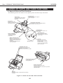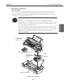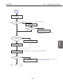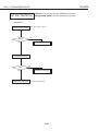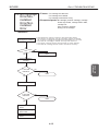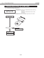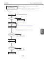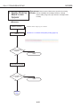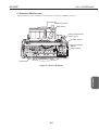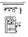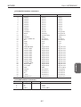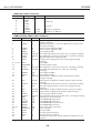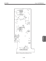
1
REVISION 0 NOV. 1999 QY8-1369-000 COPYRIGHT 1999 CANON INC. CANON BJC-8200 1199 SE 0.28-0 PRINTED IN JAPAN (IMPRIME AU JAPON) 1199 SE 0.28-0 Target Readers This manual is published by Canon Inc. for qualified persons and contains the necessary technical information for technical theory, installation, maintenance, and repair of products. This manual covers all localities where the products are sold. For this reason, it may contain information that does not apply to your locality. Revisions This manual may include technical inaccuracies or typographical errors due to improvements or changes in the products. When amendments are made to the content of this manual, Canon will issue technical information as the need arises. In the event of major alterations to the content of this manual over a long or short period, Canon will publish a revised version of the manual. The following paragraphs do not apply to any countries where such provisions are inconsistent with local law. Trademarks The product names and company names appearing in this manual are the registered trademarks or trademarks of the individual companies. Copyright This manual is copyrighted and all rights reserved. Under the copyright laws, this manual may not be copied, reproduced, or translated into other languages, in whole or in part, without the express written consent of Canon Inc. except in the case of internal business use. Copyright 1999 by Canon Inc. CANON INC. BJ Products Quality Support Dept. 16-1, Shimonoge 3-chome, Takatsu-ku, Kawasaki-shi, Kanagawa 213, Japan This manual was produced on an Apple Macintosh Power Mac 9600/233 personal computer and Apple LaserWriter II NTX-J laser beam printer; final pages were printed on Varityper 5300 with 4000-J RIP. A Canon mo-5001S Magneto-Optical Storage Subsystem with mo-502M Magneto-Optical Storage Disk Cartridge and mo-IF2 interface kit were used for storing large volumes of page layout and graphic data for this manual. All graphics were produced with MACROMEDIA FREEHAND 7.0J. All documents and all page layouts were created with QuarkXPress 3.3J. I. ABOUT THIS MANUAL Part 3: OPERATION This part explains how to operate the unit properly, and how to use the service mode. Part 4: TROUBLESHOOTING This part explains how to resolve problems of the unit, and contains information on how to locate and replace serviceable units and parts. It is divided into two sections: "Troubleshooting by Errors" and "Troubleshooting by Symptoms." Part 5: REFERENCE This part outlines the unit operation giving technical information on hardware, and contains block diagrams, pin assignments, and wiring/circuit diagrams. REF This manual does not contain complete information required for disassembling and assembling the BJC-8200 printer. Please also refer to the separate Parts Catalog. I MAINTENANCE This part explains maintenance of the unit. It includes precautions and details for disassembly and assembly, and adjustments required when assembling. OPERATION Part 2: MAINTENANCE TROUBLE SHOOTING This part outlines the product and its specifications. REFERENCE Part 1: PRODUCT SPECIFICATIONS PRODUCT SPECIFICATION This manual is divided into five parts containing the information required for servicing the BJC-8200 printer. II. TABLE OF CONTENTS Page 1- 1 1- 1 1- 2 1- 3 1- 3 1- 3 1- 3 1- 4 1- 4 1- 4 1- 4 1- 4 1- 6 1- 6 1- 6 1- 7 1- 7 1- 8 1- 8 Part 1: PRODUCT SPECIFICATIONS 1. PRODUCT OUTLINE 1.1 Product Outline 1.2 Features 2. SPECIFICATIONS 2.1 Main Unit Specifications 2.1.1 Main unit specifications 2.1.2 Product life 2.2 Paper Specifications 2.2.1 Paper sizes 2.2.2 Paper measurement 2.2.3 Printable area 2.3 BJ Cartridge 2.4 Interface Specifications 2.4.1 Parallel interface 2.4.2 Serial (USB) interface 2.5 Printer Driver 2.6 Scanner Cartridge IS-52 (Optional) 3. NAMES OF PARTS AND THEIR FUNCTIONS 3.1 Names of Parts and Their Functions Part 2: MAINTENANCE 2- 1 2- 1 2- 1 2- 2 2- 2 2- 3 2- 3 2- 4 2- 4 2- 5 2- 5 2- 6 2- 6 2- 6 2- 7 2- 7 2- 8 2- 9 2- 9 2- 9 2 -10 2 -11 2 -12 2 -12 2 -13 2 -13 1. PERIODICAL REPLACEMENT/MAINTENANCE 1.1 Parts for Periodic Replacement 1.2 List of Periodic Maintenance 2. DISASSEMBLY AND REASSEMBLY 2.1 List of Tools 2.2 Operation Precautions 2.2.1 Ink paths 2.2.2 Ink mist 2.2.3 Precautions for damage due to static electricity 2.2.4 Precautions for transporting the printer 2.2.5 Precautions on spur tip deformation 2.3 Precautions for Disassembling and Reassembling the Printer 2.3.1 Unlocking the carriage 2.3.2 Removing/installing self tap screws 2.3.3 Adjustable bushings supporting the carriage shaft 2.3.4 Feed gear 2.4 Grease Application 2.5 Adjustment/Setting Procedures 2.5.1 Adjustments (Timing, adjustment, time, tool) 2.5.2 Cleaning the pick-up roller 2.5.3 Print head position adjustment 2.5.4 Setting the EEPROM 3. OPERATION CHECK AFTER DISASSEMBLING/REASSEMBLING 3.1 Confirmation Methods 4. TRANSPORTING THE PRINTER 4.1 Transporting the Printer Page 3- 1 3- 1 3- 3 Part 3: OPERATION 1. FUNCTIONS RELATED TO PRINTER OPERATION 1.1 Error Display 1.2 Descriptions of Error Indications II Page 3- 4 3- 4 3- 4 3- 5 3- 5 3- 6 3- 6 3- 6 3- 7 3- 8 3- 8 3- 9 3 -10 3 -11 3 -11 3 -12 3 -12 3 -13 1.3 BJ Status Monitor 1.3.1 Main functions of the BJ status monitor 1.3.2 Items displayed on the BJ status monitor 1.4 Function Settings 1.4.1 Function settings using the printer driver 1.5 Off-line Operation 1.5.1 Cleaning operation 1.5.2 Nozzle check pattern printing 1.5.3 Replacing the cartridge/ink tank 2. SERVICE MODE 2.1 Service Mode Operations 2.2 Service Test Print 2.3 Printing EEPROM Information 2.4 Resetting the EEPROM 2.5 Setting the Waste Ink Counter 2.6 Setting the Model 2.7 Adjusting the Head Position 2.8 Roller Cleaning Part 4: TROUBLESHOOTING 4- 1 4- 1 4- 4 4- 5 4 -14 4 -14 1. TROUBLESHOOTING BY DISPLAYED ERRORS 1.1 Initial Flowchart 1.2 Error List (Indicator/Beeper/Error Code) 1.3 Troubleshooting by Errors 2. TROUBLESHOOTING BY SYMPTOMS 2.1 Troubleshooting by Symptoms Part 5: REFERENCE 5- 1 5- 1 5- 2 5- 3 5- 4 5- 5 5- 6 5- 6 5 -10 5 -13 5 -14 5 -15 5 -15 5 -16 5 -16 5 -16 5 -17 5 -17 5 -17 5 -18 5 -18 5 -18 5 -20 5 -21 1. TECHNICAL REFERENCE 1.1 Functions of the Paper Feed Unit 1.2 Carriage Function 1.3 Purge Unit Functions 1.4 BJ Cartridge 1.5 Detection With Sensors 2. CONNECTOR POSITIONS AND PIN ASSIGNMENT 2.1 Logic Board 2.2 Carriage Board 2.3 BJ Cartridge 2.4 Scanner Cartridge 2.5 AC Adapter 2.6 DC Power Cable 2.7 Carriage Motor 2.8 Paper Feed Motor 2.9 Purge Motor 2.10 Ink Sensor 2.11 Paper Thickness Sensor 2.12 Purge Sensor 3. CIRCUIT DIAGRAM 3.1 Parts Layout 3.1.1 Logic board 3.1.2 Carriage board 3.2 Circuit Diagrams III III. ILLUSTRATION INDEX Page 1- 1 1- 5 1- 8 Part 1: PRODUCT SPECIFICATIONS Figure 1- 1 Figure 1- 2 Figure 1- 3 Printer Appearance Printable Area Names of Parts and Their Functions Part 2: MAINTENANCE 2- 3 2- 4 2- 5 2- 5 2- 6 2- 7 2- 7 2- 8 2 -10 Figure Figure Figure Figure Figure Figure Figure Figure Figure 222222222- 1 2 3 4 5 6 7 8 9 Ink Paths Ink Mist Capping Position Spur Unit Unlocking the Carriage Adjustable Bushings Supporting the Carriage Shaft Precautions on Feed Gears Grease Points Print Position Adjustment Pattern Part 3: OPERATIONS 3- 1 3- 4 3- 5 3- 7 3- 9 3 -10 3 -11 3 -13 Figure Figure Figure Figure Figure Figure Figure Figure 33333333- 1 2 3 4 5 6 7 8 Operation Panel BJ Status Monitor (Sample) Printer Driver Utility (Sample) Nozzle Check Pattern Print Service Test Print (Sample) EEPROM Information Print (Sample) A Guide to Determine the Amount of Waste Ink Absorbed (Sample) Head Position Adjustment Pattern (Sample) Part 5: REFERENCE 5- 1 5- 2 5- 3 5- 4 5- 5 5- 6 5- 6 5 -10 5 -13 5 -14 5 -15 5 -15 5 -16 5 -16 5 -16 5 -17 5 -17 5 -17 5 -18 5 -19 5 -20 Figure Figure Figure Figure Figure Figure Figure Figure Figure Figure Figure Figure Figure Figure Figure Figure Figure Figure Figure Figure Figure 555555555555555555555- 1 2 3 4 5 6 7 8 9 10 11 12 13 14 15 16 17 18 19 20 21 Paper Feed Path Carriage Unit Purge Unit BJ Cartridge Sensor Position Logic Board Block Diagram Carriage Board BJ Cartridge Scanner Cartridge AC Adapter DC Power Cable Carriage Motor Paper Feed Motor Purge Motor Ink Sensor Paper Thickness Sensor Purge Sensor Logic Board (Top View) Logic Board (Bottom View) Carriage Board IV IV. TABLE INDEX Page 3- 2 Part 3: OPERATION TABLE 3- 1 ERROR DISPLAY Part 4: TROUBLESHOOTING 4- 4 TABLE 4- 1 ERROR DISPLAY Part 5: APPENDIX 5- 3 TABLE 5- 1 AMOUNTS OF INK USED DURING CLEANING (GUIDE) V This page intentionally left blank VI Part 1 PRODUCT SPECIFICATIONS Page 1- 1 1- 1 1- 2 1- 3 1- 3 1- 4 1- 4 1- 6 1- 7 1- 7 1- 8 1- 8 1. PRODUCT OUTLINE 1.1 Product Outline 1.2 Features 2. SPECIFICATIONS 2.1 Main Unit Specifications 2.2 Paper Specifications 2.3 BJ Cartridge 2.4 Interface Specifications 2.5 Printer Driver 2.6 Scanner Cartridge IS-52 (Optional) 3. NAMES OF PARTS AND THEIR FUNCTIONS 3.1 Names of Parts and Their Functions Part 1: PRODUCT SPECIFICATIONS BJC-8200 1. PRODUCT OUTLINE This printer, with ultra small 4-pl ink droplets and new light-and-dark ink system, delivers graininess-free, photographic-quality, high-resolution images. In addition, the support of a high-resolution scanner cartridge and adapter for direct connection to digital cameras, as optional equipment, and the USB interface as standard equipment, prove this printer a highly value-added product. This printer is intended to increase the market share where photo-realistic output is demanded, targeting users who need excellent photographic quality printing. Operation Panel Paper Paper Guide Auto Sheet Feeder Front Cover Paper Output Tray Parallel Interface Connector Paper Thickness Lever BC-50 BJ Cartridge Optional Scanner USB Interface Connector IS-52 Scanner Cartridge Cartridge Container (Supplied with Scanner Cartridge) Figure 1-1 Printer Appearance 1-1 PRODUCT SPECIFICATION 1.1 Product Outline Part 1: PRODUCT SPECIFICATIONS BJC-8200 1.2 Features 1) Highest resolution photo imaging without any graininess. (4-pl ink droplets; new light-and-dark ink with light ink density of 1/6.) 2) Optionally available 600 dpi scanner cartridge. 3) Both IEEE1284-compatible, 8-bit parallel interface and USB interface, as standard equipment. 4) Individually replaceable ink tanks for each color for reduced running costs. 5) Ink-low detection using both optical and dot-counting systems and translucent ink tanks allow visual checking of the ink level. 6) A mechanism to allow manual correction of print position misalignment of each color, as well as in bi-directional printing. 7) A function to notify of the optimum head gap setting of the paper thickness lever. 1-2 Part 1: PRODUCT SPECIFICATIONS BJC-8200 2. SPECIFICATIONS Type Paper feeding method Resolution Throughput (Reference values) ppm Printing direction Printing width Line feed speed Interface ASF capacity Detection functions Acoustic noise during operation Environmental conditions Power supply External dimension Weight Certification Optional parts Desktop serial printer Automatic and manual feeding 1200dpi x 1200dpi (maximum resolution) Draft Standard High Bk (PC Magazine) 3.15 2.24 0.37 Color (A4 Full Page) 2.0 1.4 0.26 Color (New Pattern) 2.0 1.4 0.26 1-pass/bidirectional 2-pass/unidirectional 4-pass/bidirectional 4-pass/unidirectional 8-pass/bidirectional Automatically switched over by driver, corresponding to selected media and print quality. 203.2 mm 161ms/line (for 256/1200-inch feed) IEEE 1284-compatible 8-bit parallel interface (Compatible/nibble/ECP) USB (without hub function) Up to 10 mm (Approx. 100 sheets of 75 g/m2 paper) Cover open Yes BJ cartridge installed Yes Scanner cartridge installed Yes Cartridge correctly installed Yes Ink-out Yes Paper-detection Yes Waste ink full Yes Paper width detection No Approx. 37 dB(A) (For 8-pass printing with a sheet feeder full of paper) (Sound pressure level: compliant with ISO9296) Operation Temperature: 5 to 35°C Humidity: 10-90% RH (No condensation) Standby Storage: 0-35°C Humidity: 10-90% RH (No condensation) Voltage/frequency Power consumption At standby AC100-120V 50/60Hz 23W (max.) 8W AC200-240V 50/60Hz 23W (max.) 8W 450 mm (W) x 327 mm (D) x 204 mm (H) Approx. 5.9 Kg (Excluding BJ cartridge) Electromagnetic radiance: VCCI, FCC, IC, CE Mark, EMC (Taiwan), C-tick Electrical safety: Electrical Safety Regulations, UL, C-UL, CB Report, CE Mark, FIMCO, GS, GCIB, SISIR, AS, Electrical Safety Regulations of Korea Environmental regulations: Blue Angel, Energy Star Scanner cartridge (See Page 1-7) 2.1.2 Product life Product life is either of the following periods, whichever is shortest. (1) From the start of use until 15,000 sheets has been fed. (2) From the start of use until 5 years lapses. 1-3 PRODUCT SPECIFICATION 2.1 Main Unit Specifications 2.1.1 Main unit specifications Part 1: PRODUCT SPECIFICATIONS BJC-8200 2.2 Paper Specifications 2.2.1 Paper sizes Canon recommends the following papers: Paper type Size Plain paper Measurement: 64-90 g/m2 A4/B5/A5/ LTR/LGL Color BJ paper High-resolution paper Glossy photo paper Glossy photo film OHP film BJ cloth LC-301 HR-101 GP-301 HG-201 CF-102 FS-101 Banner paper T-shirt transfer Glossy photo card BP-101 TR-201 FM-101 Envelope COM#10 A4/B5 A4/B5/LTR A4/LTR A4/LTR A4/LTR (L)356 x (W)251 mm A4/LTR A4/LTR (L)216 x (W)119 mm (L)105 x (W)241 mm (L)110 x (W)220 mm A4/LTR DL Photo paper pro PR-101 Stacked in the ASF 10 mm or less (Approx. 100 sheets of 75-g/m2 paper) 75 sheets 80 sheets 10 sheets* 1 sheet 10 sheets** 1 sheet Paper thickness lever position Up Up Up Up Up Up Down 1 sheet 1 sheet 1 sheet*** Down Up Up 10 sheets or less Down 10 sheets or less Down 1 sheet* Up Thick paper Measurement: A4/LTR Manual feed Down 2 91-500 g/m only * Always use GP-301/PR-101 with the cleaning plate underneath it. ** Always use OHP film with a sheet of plain paper beneath it. *** Always use glossy photo paper with the associated auxiliary sheet beneath it. 2.2.2 Paper measurement Automatically-fed paper Manually-fed paper 64-90 g/m2 64-500 g/m2 (up to 0.6 mm) 2.2.3 Printable area Refer to Figure 1-2 Printable Area. 2.3 BJ Cartridge Construction 6 color integrated head, with separately-replaceble ink tanks for each color Print head 256 x 6 nozzles (Placed in line for each color) Ink color BK, C, M, Y, Photo-C, Photo-M Ink tank 6 separate tanks (One tank for each color) Weight Approx. 80 g (excluding ink tanks) Cartridge life 5000 sheets (7.5%-duty print pattern) or 2 years in box/1 year out of box. Print capacity Approx. 240 sheets/tank (7.5%-duty print pattern) Note) The BJ head, available as a consumable part, does not include ink tanks. 1-4 Part 1: PRODUCT SPECIFICATIONS BJC-8200 Letter (LTR)/Legal (LGL) Size A4/A5/B5 Size 3.0mm 3.0mm 28.0mm PRODUCT SPECIFICATION 28.0mm 20.0mm 5.0mm 3.4mm 3.4mm 20.0mm 5.0mm 6.4mm 6.4mm Envelope 3.0mm :Recommended printing area :Printable area 5.0mm 6.4mm COM#10: 30.4mm DL : 9.4mm Banner Paper 5.0mm 3.0mm 3.4mm 1 2 3 4 5 6 3.4mm *: For 6-page printing 28.0mm Figure 1-2 Printable Area 1-5 20.0mm Part 1: PRODUCT SPECIFICATIONS BJC-8200 2.4 Interface Specifications 2.4.1 Parallel interface 1) Interface type IEEE 1284 compatible parallel interface 2) Data transfer: 8-bit parallel transfer method (Compatible/nibble/ECP mode supported) 3) Signal voltage levels Input: "Low" level: 0.0V to +0.8V "High" level: +2.4V to +5.0V Output: "Low" level: 0.0V to +0.8V "High" level: +2.4V to +5.25V 4) Input/Output Each signal pulled up with +5V 5) Interface cable Twisted-pair double shielded cable Material: AWG No. 28 or higher (AWG: American Wire Gauge) Length: Up to 2.0 m. 6) Interface connector: Printer-side Amphenol 57-40360 (or equivalent) Cable-side Amphenol 57-30360 (or equivalent) 7) Input/Output signal and pin arrangements Refer to Part 5: 2. CONNECTOR POSITIONS AND PIN ASSIGNMENT (Page 5-6) for details. 2.4.2 Serial (USB) interface 1) Interface type USB Interface (Universal Serial Bus; USB Specification Release 1.0) 2) Data transfer: Control transfer method Bulk transfer method 3) Signal voltage level Input: Input difference sensitivity: +0.2V (Max) Common-mode difference: +0.8V to +2.5V Output: Static output high: +2.8V to +3.6V Static output low: 0.0V to +0.3V 4) Input/Output Each signal pulled up with 3.3V 5) Interface cable Cable Twisted pair shielded cable, up to 2.0 m Full-speed mode must be supported. Material: AWG No. 28 or higher (AWG: American Wire Gauge) 6) Interface connector Printer-side USB standard, Series B receptacle Cable-side USB standard, Series B plug 7) Input/Output signal and pin arrangements Refer to Part 5:2. CONNECTOR POSITIONS AND PIN ASSIGNMENT (Page 5-6) for details. 1-6 Part 1: PRODUCT SPECIFICATIONS BJC-8200 The drivers that can be used for this printer: 1) For Windows: Raster driver (For Win3.1/95/98) Raster driver (For Win NT4.0/(5.0)) 2) For Macintosh: Macintosh driver for USB I/F Serial I/F drivers are not available. 2.6 Scanner Cartridge IS-52 (Optional) Type Light source Resolution Paper width Scannable band width Paper thickness Operation environment Life span Cartridge replacement type color scanner 3 LED's for RGB 600x600, 300x300, 200x200, 150x150, and 75x75 dpi 208.2mm Up to 10.8mm Up to 0.25mm OS: Win98/95/NT4.0, Mac OS 8.1 or later I/F: Parallel (IEEE1284-compliant)/USB Memory: 8MB (16MB or more recommended.) Unused Disk space: (50MB at least) 1200 sheets (A4 paper) 1-7 PRODUCT SPECIFICATION 2.5 Printer Driver Part 1: PRODUCT SPECIFICATIONS BJC-8200 3. NAMES OF PARTS AND THEIR FUNCTIONS 3.1 Names of Parts and Their Functions The following shows the names of the printer parts and their major functions: Paper Support Extend this paper rest to support larger sized paper. Paper Guide Lightly press this guide against the left side of paper sheets to align them. Front Cover Open this cover when replacing the BJ cartridge or clearing paper-jams. Auto Sheet Feeder (ASF) Set paper here. You can set multiple sheets; each sheet is fed one by one. POWER Button Press this button to power on or off the printer. RESUME Button After correcting a problem, press this button to make the printer ready. Paper Output Tray Allows smooth ejection of paper and reduces paper friction. Paper Thickness Lever Allows you to adjust the gap between the print head and paper surface by raising this lever up and down. The illustration shows the lever in the "Up" position. Indicator Not lit when powered off. When lit in green, the printer is ready to print. When lit or blinking in orange, an error has occurred and the printer cannot print. Operation Panel Cartridge Lock Lever Use this lever to secure the BJ cartridge in the carriage. Raise it to remove the BJ cartridge. Manual Paper Feed Slot To feed paper manually, insert paper here. Interface Connector Connects to the interface cable from the computer. Two types of connector interfaces are provided: USB and parallel. Carriage Either BJ cartridge or optional Scanner cartridge is installed. Figure 1-3 Names of Parts and Their Functions 1-8 Part 2 MAINTENANCE Page 2- 1 2- 1 2- 1 2- 2 2- 2 2- 3 2- 6 2- 8 2- 9 2 -12 2 -12 2 -13 2 -13 1. PERIODICAL REPLACEMENT/MAINTENANCE 1.1 Parts for Periodic Replacement 1.2 List of Periodic Maintenance 2. DISASSEMBLY AND REASSEMBLY 2.1 List of Tools 2.2 Operation Precautions 2.3 Precautions for Disassembling and Reassembling the Printer 2.4 Grease Application 2.5 Adjustment/Setting Procedures 3. OPERATION CHECK AFTER DISASSEMBLING/REASSEMBLING 3.1 Confirmation Methods 4. TRANSPORTING THE PRINTER 4.1 Transporting the Printer Part 2: MAINTENANCE BJC-8200 1. PERIODICAL REPLACEMENT/MAINTENANCE 1.1 Parts for Periodic Replacement Level User Service personnel Parts for periodical replacement None None Consumable BJ cartridge (Ink tanks not included) Ink tank (Black) Ink tank (Cyan) Ink tank (Magenta) Ink tank (Yellow) Ink tank (Photo cyan) Ink tank (Photo magenta) None 1.2 List of Periodic Maintenance Level User Service personnel Location None None 2-1 MAINTENANCE Level User Service personnel Part 2: MAINTENANCE BJC-8200 2. DISASSEMBLY AND REASSEMBLY 2.1 List of Tools The following are the tools necessary for disassembly and reassembly: Ordinary tools Philips screwdriver Blade screwdriver Long-nose pliers Tweezers Flat brush Multimeter Special tools (part No.) Grease MOLYKOTE PG-641 (CK-0562-000) Grease EU-1 (QY9-0037-000) For For For For For For Note removing and replacing screws removing plastic parts removing and replacing springs removing and installing flexible cables applying grease (one per grease type) troubleshooting Note To be applied to specified locations (See Page 2-8) To be applied to the portion of the guide shaft which the carriage slides over. 2-2 Part 2: MAINTENANCE BJC-8200 2.2 Operation Precautions 2.2.1 Ink paths CAUTION The ink is not harmful to the human body, but contains some organic solvents. Black, cyan, magenta, photo cyan, and photo magenta ink contain glycerin 56-81-5, isopropyl alcohol 67-63-0, ethylene glycol 107-21-1, and di-ethylene glycol 111-46-6 respectively. Yellow ink contains glycerin 5681-5 and isopropyl alcohol 67-63-0. Be careful not to get the ink into your mouth or eyes. If the ink gets into your eyes, wash with plenty of water and consult a doctor. In case a large amount of ink has been swallowed, consult a doctor immediately. The ink contains dyes. If clothing is stained with the ink, the ink may not be removed completely. Maintenance Jet Receiving Section BJ Cartridge Wiper Maintenance Jet Receiving Section Waste Ink Absorber Figure 2-1 Ink Paths 2-3 Head Cap MAINTENANCE Be careful not to touch the ink paths. Ink on hands could stain the printer, work table, or clothes. The ink paths include the BJ cartridge ink tank outlet, the BJ cartridge ink filters and nozzles, the maintenance jet receiving section, the head caps, the wipers, and the waste ink absorber. Part 2: MAINTENANCE BJC-8200 2.2.2 Ink mist The BJ cartridge ejects ink onto the paper during printing. After the printer is used for a long period or used heavily, the ink mist bouncing back from the paper could accumulate and soil the front cover, platen, and the area around the operation panel, purge unit, and paper output tray. Carefully wipe off the ink mist with a soft dampened cloth so that hands or clothing will not be stained by soiled parts during servicing. Also, be careful not to smudge the pick roller when removing the upper cover. Front Cover Upper Cover Around Operation Panel Platen Around Purge unit Paper Output Tray Figure 2-2 Ink Mist 2.2.3 Precautions for damage due to static electricity Static electricity can be generated by clothing rubbing against each other and may accumulate in the body. If you touch electrical elements, the discharge of static electricity could damage them, or change their electrical characteristics. For this reason, avoid touching the ink sensor contacts or the printer's BJ cartridge contacts. 2-4 Part 2: MAINTENANCE BJC-8200 2.2.4 Precautions for transporting the printer Emergency Fixing Tape Figure 2-3 Capping Position 2.2.5 Precautions on spur tip deformation Take care not to bend the tips of the spurs. The tips of the spurs make contact with printed paper and are contaminated with ink, but due to their small surface contact area, the tips, cleaned by the spur cleaners, will not stain the printed paper. However, if the tips are bent and their contact surface area increases, they collect more ink and are not easily cleaned by the spur cleaners, and thereby stain the printed paper by making dotted lines on it. Spurs Figure 2-4 Spur Unit 2-5 MAINTENANCE When turned off by the POWER button, the BJ cartridge is capped and the carriage is locked in place at the capping position by the lock arm. When the printer cannot be powered off by the POWER button for transportation, etc., move the carriage to the capping position by hand and secure it with tape before transporting the printer. Remove the ink tanks and keep them in a vinyl bag while the printer is being transported. Part 2: MAINTENANCE BJC-8200 2.3 Precautions for Disassembling and Reassembling the Printer Note the following when disassembling or reassembling the printer. When disassembling or reassembling the printer, refer to the parts catalog. The numbers in the parts catalog illustrations indicate the disassembly sequence. 2.3.1 Unlocking the carriage When the printer is shipped from the factory (or when the cartridge is installed and the power has been turned off normally), the carriage is locked in the capping position to secure the cartridge during transportation. When the printer is powered on properly, the carriage is unlocked automatically. If the printer cannot be powered on normally, it will be necessary to manually unlock the carriage. This can be done by turning the gear of the purge unit in the direction of the arrow by finger, as shown in Figure 2-5 Unlocking the Carriage. Figure 2-5 Unlocking the Carriage 2.3.2 Removing/installing self tap screws The printer unit is secured to the lower case with tap screws. Once the tap screws have been removed, pieces of the molding remain attached to the screw threads. Reinstalling the tap screws in this condition can damage the screw threads. To prevent this, when reinstalling screws, remove the remains in advance or, where possible, use new screws. Also, blow away any remains on the mold before reinstalling the tap screws. 2-6 Part 2: MAINTENANCE BJC-8200 2.3.3 Adjustable bushings supporting the carriage shaft The adjustable bushings supporting the carriage shaft are adjusted and secured to the printer frame so that the ideal gap, or head gap, between the BJ cartridge nozzle and platen is maintained for best print quality. The fixing screws are painted red to protect against careless removal. Do not loosen the fixing screws. Fixing Screw Adjustable Bushing Supporting the Carriage Shaft Fixing Screw Adjustable Bushing Supporting the Carriage Shaft Figure 2-6 Adjustable Bushings Supporting the Carriage Shaft 2.3.4 Feed gear Be careful not to touch the gears in the paper feed unit, especially the feed roller gear, during disassembling or reassembly. Although covered, even slight damage to it could affect paper feeding when printing at high resolution. Gear Cover Feed Roller Gear Eject Roller Gear Figure 2-7 Precautions on Feed Gears 2-7 MAINTENANCE Printer Frame Part 2: MAINTENANCE BJC-8200 2.4 Grease Application Apply greases at the points shown below. Apply a thin film of grease using the flat brush. For the grease (EU-1) for the grease pad, do not use a brush but apply directly. For printer disassembly and reassembly procedures, refer to the parts catalog. CAUTION When applying greases, be careful to not get any on the wiper, cap, or encoder film. If grease is applied to them, wipe them clean immediately. Cam Sliding Surface Approx. 24 mg (Molykote PG-641 ) Grease Pad Approx. 35 mg (EU-1) Cam Sliding Surface Approx. 24 mg (Molykote PG-641 ) Eject Roller Gear Teeth (apply to all teeth evenly) Approx. 60 mg (Molykote PG-641 ) Guide Shaft Sliding Surface Feed Roller Gear Teeth (apply the proper amount of grease so as not to drip) (apply to all teeth evenly) Approx. 90 mg (EU-1) Approx. 96 mg (Molykote PG-641) Guide Frame Underside (apply a thin coat of grease over the entire surface) Approx. 48 mg (Molykote PG-641) LF Gear Teeth (apply to all teeth evenly) Approx. 72 mg (Molykote PG-641 ) Paper Thickness Lever Approx. 12 mg (Molykote PG-641) Feed Roller Sliding Surface Approx. 24 mg (Molykote PG-641) Feed Roller Sliding Surface Approx. 12 mg (Molykote PG-641) Figure 2-8 Grease Points 2-8 Part 2: MAINTENANCE BJC-8200 (1) User level Timing When BJ cartridge is replaced. When pick-up roller becomes contaminated. (2) Service personnel level Timing When BJ Cartridge is replaced. (Replacement of carriage parts) When logic board/waste ink absorber is replaced When pick-up roller becomes contaminated. Adjustment Adjust print head position Clean pick-up roller Time 3 min. Tool HR-101 (A4) 3 min. Cleaning plate Adjustment Adjust print head position Set EEPROM Time 3 min. Tool HR-101 (A4) 1 min. None Clean pick-up roller 3 min. Cleaning plate 2.5.2 Cleaning the pick-up roller If surface-processed paper or High-Resolution Paper (HR-101) is used in large quantity, paper feeding may be affected due to paper dust adhering to the pick-up roller. If this happens, clean the pick-up roller inside the printer with the cleaning plate, supplied with the unit. You can perform this operation by setting the printer into Service Mode, or via the printer drive utility. For details, refer to Part 3: 2.1 Service Mode Operations (Page 3-8) and Part 3: 1.4.1 Function settings using the printer driver (Page 3-5). 2-9 MAINTENANCE 2.5 Adjustment/Setting Procedures 2.5.1 Adjustments (Timing, adjustment, time, tool) Part 2: MAINTENANCE BJC-8200 2.5.3 Print head position adjustment As a result of inherent product variations in each BJ cartridge or its specific seating position, inaccurate dot placement may occur, resulting in poor printing. To correct this, after installing the BJ cartridge, perform the automatic print head position adjustment, one of the utilities the printer driver package provides. If a computer is not available, you can perform the print head position adjustment in Service Mode. For the procedures, refer to Part 3: 2.1 Service Mode Operations (Page 3-8). Set at least one sheet of A4 high-resolution paper into the ASF, and carry out the print head position adjustment from the printer driver's Maintenance sheet. Service Mode Registration Pattern Head Position Adjustment Pattern Figure 2-9 Print Position Adjustment Pattern CAUTION If normal paper is used to adjust the print head position, the ink may bleed, preventing accurate determination. Use High-Resolution Paper (HR101) or Glossy Photo Paper (GP-301), which provide higher quality printing. Also, be sure to perform the adjustment with the paper thickness lever raised. 2-10 Part 2: MAINTENANCE BJC-8200 2.5.4 Setting the EEPROM The EEPROM on the logic board stores the total amount of waste ink absorbed, function settings, and other information specific to the printer. For this reason, be aware of the following when servicing the printer. 2) After logic board replacement Visually check the waste ink absorber's ink level following the procedures in Part 3: 2.5 Setting the Waste Ink Counter (Page 3-11), and replace the absorber or set the counter as necessary. The counter can be set to 0% (Reset), 25%, 50%, and 75%. The EEPROM data of a replacement logic board is not defined. After replacing the logic board, you must always reset the EEPROM, check the waste-ink absorber, set the ink counter, set the model name, and adjust the head position. 3) After waste ink absorber replacement After replacing the waste ink absorber following an ink-full warning or error, reset the waste ink counter. CAUTION NOTE Previous EEPROM data cannot be checked from the Service Mode once the EEPROM has been reset. Always perform the check before resetting the EEPROM. All information such as function status, number of sheets passed, waste ink amount, etc., except for the USB serial number, will be lost when the EEPROM is reset. It is not possible to write data, such as function status and the number of sheets passed, of the old EEPROM to the new EEPROM. This printer presumes that the ink full alarm/error does not occur before the life of the printer has been reached. However, depending on the usage conditions, such as frequency of powering on/off and frequency of the BJ cartridge replacement, the waste ink amount varies. As a result, the frequency of the alarm/error also varies. The ink full alarm occurs when the absorbed ink amount approaches a limit. In this case, although you can operate the printer again by pressing the RESUME button, the ink full error will occur in the end. (At that time, you can no longer continue operation by pressing the RESUME button.) Refer to Part 3: 2.1 Service Mode Operations (Page 3-8) for details on how to check/reset stored data in the Service Mode. 2-11 MAINTENANCE 1) Before repair You can check the data stored in the EEPROM by performing the test print or EEPROM information print for servicing. In particular, the number of total sheets passed will give a good idea of how frequently the printer has been used. Part 2: MAINTENANCE BJC-8200 3. OPERATION CHECK AFTER DISASSEMBLING/REASSEMBLING 3.1 Confirmation Methods After reassembling, confirm the operation of the printer by conducting the following procedures: 1) Test print for servicing using the printer only. Verify correct print out using the method stated in Part 3: 2.1 Service Mode Operations (Page 3-8). After replacing either the logic board or the waste ink absorber, in addition to (1), it is necessary to confirm the following points: When the: Logic board is replaced Waste ink absorber is replaced Check items: On the service/factory test print, confirm that the ROM version and model name are correct, and that the number of sheets passed has been cleared, and the waste ink counter is set appropriately. Printing the nozzle check pattern via the printer driver is possible. On the service/factory test print or EEPROM information print, confirm that the total waste ink amount has been cleared. 2-12 Part 2: MAINTENANCE BJC-8200 4. TRANSPORTING THE PRINTER To prevent the ink from leaking or drying out in the BJ cartridge nozzles during transportation, keep the BJ cartridge installed in the printer, or stored in the cartridge container. The ink tanks must be removed from the BJ cartridge and put into a vinyl bag while the printer is being transported. Transport the printer (for return after repair) with the carriage locked in place. Refer to Part 2: 2.2.4 Precautions for transporting the printer (Page 2-5). When transporting the printer, follow the procedures below: 1) Remove the ink tanks from the BJ cartridge and place in a vinyl bag. 2) Press the POWER button to turn off the printer. After the printer moves the carriage to the home position for cleaning and locks the carriage in place, the indicator will go out. 3) Disconnect the interface cable(s). 4) Unplug the AC power cord from the wall outlet. 5) Open the front cover and visually confirm that the carriage is locked in the capping position (on the right side of printer). If the carriage is not in the capping position, move it manually to the capping position by using the carriage belt, and secure it there with tape. 6) Close the front cover. 7) Pack the printer in its original packing material. If the original packing materials are not available, pack the printer in sufficient shock absorbing material. CAUTION Do not unplug the printer before switching off the printer with the POWER button, otherwise, the BJ cartridge's nozzles will not be capped, which may result in ink leaking or drying-out. 2-13 MAINTENANCE 4.1 Transporting the Printer Part 2: MAINTENANCE BJC-8200 This page intentionally left blank 2-14 Part 3 OPERATION Page 3- 1 3- 1 3- 3 3- 4 3- 5 3- 6 3- 8 3- 8 3- 9 3 -10 3 -11 3 -11 3 -12 3 -12 3 -13 1. FUNCTIONS RELATED TO PRINTER OPERATION 1.1 Error Display 1.2 Descriptions of Error Indications 1.3 BJ Status Monitor 1.4 Function Settings 1.5 Off-line Operation 2. SERVICE MODE 2.1 Service Mode Operations 2.2 Service Test Print 2.3 Printing EEPROM Information 2.4 Resetting the EEPROM 2.5 Setting the Waste Ink Counter 2.6 Setting the Model 2.7 Adjusting the Head Position 2.8 Roller Cleaning Part 3: OPERATION BJC-8200 1. FUNCTIONS RELATED TO PRINTER OPERATION 1.1 Error Display This printer displays errors using the indicator and beeper. If an error occurs, the printer displays an error code in the status monitor to show the error status. POWER Button RESUME Button Figure 3-1 Operation Panel 3-1 OPERATION Indicator Part 3: OPERATION BJC-8200 For more information on corrective measures against the following errors, refer to PART 4: TROUBLESHOOTING. TABLE 3-1 ERROR DISPLAY Error [Recoverable by users] Paper feed error Paper jam error Ink out error BJ cartridge not-installed error BJ cartridge mis-installed error BJ cartridge error Waste ink full warning [Unrecoverable by users] Carriage error Purge error ASF sensor error Temperature sensor error Waste ink full error Head temperature error EEPROM error ROM error RAM error Other hardware error [Other warning] Ink-low warning Head temperature warning Indicator Lights Lights Lights Lights in in in in Beeper Orange Orange Orange Orange 2 3 4 5 Error code times times times times Reference page Page Page Page Page 4-11 4-11 4-12 4-13 Lights in Orange 6 times Page 4-13 Lights in Orange Lights in Orange 7 times 8 times Page 4-13 Page 4-9 Blinks Blinks Blinks Blinks Blinks Blinks Blinks Blinks Blinks Blinks in in in in in in in in in in Orange Orange Orange Orange Orange Orange Orange Orange Orange Orange in 2 times in 4 times 5 times 6 times 7 times 8 times 9 times 10 times 11 times 12 times No indication (To be reported to host) No indication (To be reported to host) 10 10 10 10 10 10 10 10 10 10 times times times times times times times times times times 5100* 5C00* 5700* 5400* 5B00* 5200* 6800* 6100* 6300* 6500* Page Page Page Page Page Page Page Page Page Page 4-6 4-7 4-8 4-5 4-9 4-10 4-5 4-5 4-5 4-5 None None * See Page 3-10 In the case of a user-recoverable error, the beeper will beep again when the RESUME button is pressed; you can confirm the type of the error by counting the number of beeps. 3-2 Part 3: OPERATION BJC-8200 For how to resolve errors, refer to Part 4: TROUBLESHOOTING. Errors recoverable by users: 1) Paper feed error Paper feed operation fails to feed paper. 2) Paper jam error Paper ejection doesn't occur, even if the eject operation is done for 14.8-inches (23inches, in the case of banner paper). 3) Ink out error Indicated when one of the ink tanks is out of ink (ink chamber and sponge). 4) BJ cartridge not-installed error The BJ cartridge is not installed. 5) BJ cartridge mis-installed error The scanner cartridge is incorrectly installed for printing, or BJ cartridge is installed for scanning. 6) BJ cartridge error Heater resistance value (rank) of the BJ cartridge is wrong. 7) Waste ink full warning The amount (stored in EEPROM) of waste ink absorbed has reached 95% of the defined capacity. Errors non-recoverable by users 8) Carriage error Incorrect carriage position or speed. 9) Purge error Purge sensor cannot detect the cam flag correctly. 10) ASF sensor error ASF sensor cannot detect the pick-up roller flag correctly. 11) Temperature sensor error The temperature inside the printer increases abnormally when the scanner cartridge is installed. (This error does not occur when the BJ cartridge is installed.) 12) Waste ink full error The data (stored in EEPROM) representing the amount of waste ink absorbed exceeds 100% of the defined capacity. 13) Head temperature error The internal temperature of the BJ cartridge is too high (exceeding 90°C). 14) EEPROM error EEPROM sum check value at soft power-on does not match the pre-defined value. 15) ROM error ROM check at hard power-on is NG. (The error occurs at soft power-on.) 16) RAM error RAM check at hard power-on is NG. (The error occurs at soft power-on.) 17) Other hardware error Another internal error has occurred. Other warnings (To be reported to the host, but not to be reported to the printer as an error.) 18) Ink-low warning The ink in one of the ink tank chambers has run out. 19) Head temperature warning When the cover is opened, the temperature inside the BJ cartridge has reached a pre-determined value (60-90°C). 3-3 OPERATION 1.2 Descriptions of Error Indications Part 3: OPERATION BJC-8200 1.3 BJ Status Monitor The BJ status monitor window shows the printer's conditions and print-job progress. Print-jobs can be cancelled from this window. 1.3.1 Main functions of the BJ status monitor 1) Show the printer's conditions and progress in real-time by means of graphics and messages. 2) Display error types and show recommended recovery methods. 3) Indicate ink-out warnings by icon and name. 4) Abort the current print-job. 1.3.2 Items displayed on the BJ status monitor 1) 2) 3) 4) 5) 6) 7) 8) 9) Printer designation Document name Printer conditions (including brief corrective measure when in error) Date and time of print start Progress status Number of pages printed Print-job abortion Cartridge installed (Photo-cartridge is always displayed.) Ink out warning Figure 3-2 BJ Status Monitor (Sample) 3-4 Part 3: OPERATION BJC-8200 1.4 Function Settings Since this printer has no function selector for setting functions, the dedicated printer driver is used for setting functions. 1.4.1 Function settings using the printer driver OPERATION From the Maintenance menu of the dedicated printer driver, you can set/execute the following items. 1) Cleaning 2) Head refreshing (long cleaning) 3) Clean the pick-up roller 4) Print the nozzle-check pattern 5) Adjust the head position. 6) Power off the printer 7) Launch the status monitor 8) Special settings • Enable ECP mode (disabled by default) • Enable high speed printing (enabled by default): printer's response time (ACKNLG) is changed from 4 to 0.9 ms. Figure 3-3 Printer Driver Utility (Sample) 3-5 Part 3: OPERATION BJC-8200 1.5 Off-line Operation This printer, when powered on (soft power-on), has an off-line operation function that allows the printer to operate independently of the computer. With the printer powered on, hold down the RESUME button, confirm the specified number of beeps for the desired operation, and then release the RESUME button. Beeps 1 2 3 Operations Cleaning Nozzle check pattern printing No operation Remarks ... Prints one sheet and ends ... 1.5.1 Cleaning operation If print output fades or blank lines appear on the output, check if the BJ head nozzles are clogged by printing the nozzle check pattern. If clogged, clean the cartridge to remove the stoppage. With the printer powered on, hold down the RESUME button and, after confirming one beep, release the RESUME button. The cleaning operation will start. You can also clean the print head from the computer using the printer driver utilities. (See Page 3-5) After cleaning, check that the nozzles have recovered by printing the nozzle check pattern again. The cleaning operation cannot be performed when the scanner cartridge is installed. 1.5.2 Nozzle check pattern printing With the printer powered on, hold down the RESUME button and, after confirming two beeps, release the RESUME button. The nozzle check pattern printing will start, feeding a sheet, which must be of A4 size, from the auto sheet feeder or manual paper feed slot. If print defects are detected in the test print, perform BJ cartridge cleaning. If five or more cleaning operations fail to solve the problem, replace the BJ cartridge with a new one. If you start the nozzle check pattern with the scanner cartridge installed, the BJ Cartridge Mis-installed Error will occur. (See Page 3-2) In this case, if you replace the scanner cartridge with the BJ cartridge, then the nozzle check pattern printing starts automatically. CAUTION Use paper of A4 size or larger for the nozzle check pattern printing. If you use smaller paper, the platen may be smeared with ink. NOTE To abort the nozzle check pattern printing, press the POWER button. The printer will switch off after ejecting the paper. 3-6 Part 3: OPERATION BJC-8200 1.5.3 Replacing the cartridge/ink tank When you open the cover of the printer with powered on, the carriage moves to the cartridge replacement position (at the center of the printer). After replacing the BJ cartridge or ink tank, when you close the cover or leave it open for 10 minutes, then the carriage returns to the home position, at the right-most position, and starts cleaning operations. (The beeper will sound before cleaning starts.) 1) Replacing the BJ cartridge/scanner cartridge Raise the cartridge lock lever, remove the BJ cartridge or scanner cartridge. When you install the scanner cartridge, keep the BJ cartridge, when removed from the printer, in the BJ cartridge container (supplied with the scanner cartridge). CAUTION The BJ cartridge may be very hot immediately after continuous operation. If you open the printer cover when the cartridge is still hot, the carriage will not move to the replacement position until it has cooled, for safety purposes. In this case, leave the printer for several minutes and then reattempt replacement. Printed with No. 1 nozzle for black (The same for each color) A B Printed with No. 256 nozzle for black (The same for each color) C D E Placement of even-numbered and odd-numbered nozzles (The same for each color) Placement setting for bi-directional print Figure 3-4 Nozzle Check Pattern Print 3-7 OPERATION 2) Replacing the ink tank You can replace the ink tanks without having to raise the cartridge lock lever. Since there are 6 separate ink tanks, one for each color, you can separately replace the ink tank that has become empty. Part 3: OPERATION BJC-8200 2. SERVICE MODE This printer has a service mode for service-related settings or performing test printing. The operator panel buttons are used to enter Service Mode. 2.1 Service Mode Operations 1) With the printer powered off, while pressing the RESUME button, press and hold the POWER button. The beeper will sound once. 2) While holding down the POWER button, release the RESUME button. Press the RESUME button twice in succession, and then release both buttons. (Each time the RESUME button is pushed, the beeper will sound once.) The indicator will blink in green, and then light in green. 3) Select one of the following service mode functions by pressing the RESUME button the specified number of times. (Each time the RESUME button is pushed, the beeper will sound once.) Times 0 1 2 3 Indicator Lights in Lights in Lights in Lights in 4 5 6 7 8 9 10 or more Lights in green Lights in orange Lights in green Lights in orange Lights in green Lights in orange Blinks in orange green orange green orange Functions Power off the printer Service test print EEPROM information print EEPROM reset (all data cleared except USB serial number) Waste ink counter setting* (see page 3-11) Model setting* (see page 3-12) Print head position pattern printing Print head position setting* (see page 3-12) Roller cleaning Plain paper feeding/ejection after roller cleaning Return to service mode selection (return to the state when step (2) above is completed.) Functions marked with "*": pressing the POWER button lets you select further subfunctions (refer to indicated pages). 4) Execute the function you have selected by pressing the POWER button. The beeper will sound once. (The printer will return to service mode selection mode after performing the function.) 3-8 Part 3: OPERATION BJC-8200 2.2 Service Test Print The service test print displays, in the header portion, such information as the control ROM version, model name, total sheets passed, and total waste ink absorbed, etc. Total waste ink absorbed (%) (absorption ratio of the waste ink absorber: %) Total sheets passed while Scanner cartridge was used Total sheets passed while BJ cartridge was used Control ROM version Model name Times of BJ cartridge replacement Times of scanner cartridge replacement Position setting for bi-directional printing BJ F850 P=Vx.xx DI=xxx.xx% Page=xxxxx/xxxxx CH=xxxxx/xxxxx R=(xx) PF=(xx xx xx) PC(A=xxxx B=xxxx C=xxxx D=xxxx) USB=(xxxxxx) Times of cleaning A Times of cleaning D USB serial No. Times of cleaning B Times of cleaning C Figure 3-5 Service Test Print (Sample) 3-9 OPERATION Factory control Part 3: OPERATION BJC-8200 2.3 Printing EEPROM Information The EEPROM stores such information as function settings, control ROM version, total number of sheets passed, total waste ink absorbed, and records the last userunrecoverable error. The information stored in the EEPROM is printed out in the EEPROM information print. The same data as written in the service test print is written at the header. The EEPROM information is especially useful for determining how heavily the printer has been used. BJ F850 P=Vx.xx ID=xxx.xx% Page=xxxxx/xxxxx CH=xxxxx/xxxxx R=(xx) Header PF=(xx xx xx) PC(A=xxxx B=xxxx C=xxxx D=xxxx) USB=(xxxxxx) SV=xxxx WP=xxxx Times of wiping Error records UR (Ke =xxx Ko =xxx Ce =xxx Co =xxx Me =xxx Mo =xxx Ye =xxx Yo=xxx Head position (LCe=xxx LCo=xxx LMe=xxx LMo=xxx DIR=xxx) adjustment value Position setting for ICK =(x/xxxxxxxxxx/xxxxxxxxxx) For each color, bi-directional printing ICC =(x/xxxxxxxxxx/xxxxxxxxxx) e: Even number nozzle o: Odd number nozzle ICM =(x/xxxxxxxxxx/xxxxxxxxxx) Ink dot counts for each color ICY =(x/xxxxxxxxxx/xxxxxxxxxx) Left : 0 if ink remains in tank and 1 if not left. ICLC =(x/xxxxxxxxxx/xxxxxxxxxx) Center : Dot counts indicating ink level in tank when left-most value is 0. ICLM =(x/xxxxxxxxxx/xxxxxxxxxx) Head serial number HDEEPROM Vxxxxx SN=xxxxxxxx PTH(K/LC=xxx LM/C=xxx M/Y=xxx) CHR(C =xxx M =xxx Y =xxx LC =xxx LM =xxx) DIR=xxx EOR(K =xxx C =xxx M =xxx Y =xxx LC =xxx LM =xxx) NG (Ke =xxx Ko =xxx Ce =xxx Co =xxx Me =xxx Mo =xxx Ye =xxx Yo =xxx) (LCe=xxx LCo=xxx LMe=xxx LMo=xxx) Internal Head Information Figure 3-6 EEPROM Information Print (Sample) The error record consists of the error code representing the most recent error that is not user-recoverable. Error Carriage error Purge error ASF sensor error Temperature sensor error Waste ink full error Head temperature error EEPROM error ROM error RAM error Other hardware error Error code 5100 5C00 5700 5400 5B00 5200 6800 6100 6300 6500 3-10 Part 3: OPERATION BJC-8200 2.4 Resetting the EEPROM The EEPROM stores such information as function settings, control ROM version, total number of sheets passed, total waste ink absorbed, and records of the last userunrecoverable error. Once the EEPROM has been reset, there is no way to recover cleared data. Be careful when resetting the EEPROM. Since the new EEPROM data is undefined, you must reset the EEPROM when replacing the logic board. After the EEPROM is reset, you need to set the waste ink counter, adjust the head position, and verify the model name. This printer detects the amount of waste ink based on the total EEPROM data - amount of waste ink absorbed. After the waste ink absorber is replaced, you must reset the data. Before replacing the logic board, you should perform the service test print or the EEPROM information print to check in advance the total amount of waste ink in the absorber. If this is not possible, visually check the waste ink absorber and replace if necessary, or set the waste ink counter to 25%, 50%, and 75%. To determine which value the counter is to be set to, check how much ink has been absorbed by the absorber, as a percentage. Use Figure 3-7 as a guide to determine the percentage. Note, however, that it depends on how the printer has actually been used. To select the counter value, select "Waste ink setting" in "2.1 Service Mode Operations" and press the POWER button. Then, press the RESUME button the number of times listed below. (The beeper will sound each time the RESUME button is pressed.) Times 0 1 2 3 4 or more Indicator Lights in green Lights in orange Lights in green Lights in orange Blinks in orange Functions Waste ink counter Waste ink counter Waste ink counter Waste ink counter No operation cleared set to 25% set to 50% set to 75% After the selection, press the POWER button, and the counter will be set to the value selected, followed by a beep sound. (Also, the printer returns to the service function selection status.) After setting the waste ink counter, verify the setting is made correctly by checking either the service test print or EEPROM information print. 50%: The 2nd layer from the top has become black. 25%: Almost no ink has been absorbed to the 2nd layer from the top. 75%: Ink is absorbed in the top layer. Figure 3-7 A Guide to Determine the Amount of Waste Ink Absorbed (Sample) 3-11 OPERATION 2.5 Setting the Waste Ink Counter Part 3: OPERATION BJC-8200 2.6 Setting the Model Since the logic board of this model is also used for the Japanese model BJF850, you need to check the model name after resetting the EEPROM when replacing the logic board. The model name is normally set to BJC-8200 after resetting; if it is not, correct the name by the following method: From the service selection mode, as shown in Part 3: 2.1 "Service Mode Operations," select "Model setting" and press the POWER button. Then, press the RESUME button the number of times shown below. (Each time the RESUME button is pressed, the beeper will sound once.) Times 0 1 2 or more Indicator Lights in green Lights in orange Blinks in orange Function BJF850 BJC-8200 No function After making the selection, press the POWER button, and the EEPROM will be set to the model selected, followed by a beep sound. (The printer will return to the service function selection status.) After setting the model name, verify the setting is correct by checking either the service test print or EEPROM information print. 2.7 Adjusting the Head Position You can adjust the head position without connecting the printer to a computer. Among the head position adjustments that users can perform using the printer driver utilities, only the bi-directional printing adjustment is carried out. After adjusting the position, verify the adjustment is made correctly by conducting a service test print or EEPROM information print. Use High-Resolution Paper (HR-101) or Glossy Photo Paper (GP-301), which provide higher quality printing. Adjust the head position in the following procedure: 1) From the service function selection status in Part 3: 2.1 "Service Mode Operations," select "Print head position pattern printing" and press the POWER button. 2) The printer starts to print the head position adjustment pattern. (See Figure 3-8 Head Position Adjustment Pattern (Sample)) After the printing, the printer will return to service function selection status. 3) Press the RESUME button 7 times to enter the print head position setting mode and press the POWER button. 4) Determine which value is the best for the head by checking the printed pattern, and then press the RESUME button the number of times listed below to set the head adjustment value accordingly. (Each time the RESUME button is pressed, the beeper will sound once.) Times 0 1 2 3 4 5 6 7 or more Indicator Lights in green Lights in orange Lights in green Lights in orange Lights in green Lights in orange Lights in green Blinks in orange Function Sets head adjustment Sets head adjustment Sets head adjustment Sets head adjustment Sets head adjustment Sets head adjustment Sets head adjustment No function value value value value value value value to to to to to to to 0 -1 +1 -2 +2 -3 +3 After making the selection, press the POWER button, and the beeper will sound once, and the head position adjustment value will be set to the value you have input. 3-12 Part 3: OPERATION BJC-8200 Figure 3-8 Head Position Adjustment Pattern (Sample) If surface-processed paper or High-Resolution Paper (HR-101) has been used in quantity, paper feeding performance may decline due to paper dust adhering to the pick-up roller. If this happens, clean the pick-up roller using the cleaning plate supplied with the printer. Clean the roller in the following procedure: 1) Dampen the white cleaner on the cleaning plate with adequate water and set the plate into the automatic feeder. 2) From the service function selection status as shown in Part 3: 2.1 "Service Mode Operations," select "Roller cleaning" and press the POWER button. 3) The pick-up roller will rotate 20 times. (The printer returns to service function selection status) 4) Insert a sheet of plain paper into the printer, with the cleaning plate set. The paper should be inserted all the way until the front edge of the paper contacts the inside of the printer. 5) Press the RESUME button 9 times to select "Plain paper feeding/ejection after roller cleaning" and press the POWER button to perform the paper feeding/ejection. 6) Carry out steps 4) and 5) once again. 7) Remove the cleaning plate and wipe the white cleaner with a dry cloth to remove water. NOTE If feeding operations do not recover to normal after the procedure above, carry out step 2) another two or three times. The cleaning plate is re-usable; you can use it repeatedly until it loses its' intended effect. You can also perform roller cleaning with the printer driver utilities. (See Page 3-5) 3-13 OPERATION 2.8 Roller Cleaning Part 3: OPERATION BJC-8200 This page intentionally left blank 3-14 Part 4 TROUBLE SHOOTING Page 4- 1 4- 1 4- 4 4- 5 4 -14 4 -14 1. TROUBLESHOOTING BY DISPLAYED ERRORS 1.1 Initial Flowchart 1.2 Error List (Indicator/Beeper/Error Code) 1.3 Troubleshooting by Errors 2. TROUBLESHOOTING BY SYMPTOMS 2.1 Troubleshooting by Symptoms Part 4: TROUBLESHOOTING BJC-8200 1. TROUBLESHOOTING BY DISPLAYED ERRORS 1.1 Initial Flowchart AC power is fed to printer. Plug in AC cord ROM check DRAM check Power on by pressing POWER button. Power on TROUBLE SHOOTING 1 beep Indicator flashes Read EEPROM Error check OK? Yes No ROM Error • 10 beeps; Indicator blinks in orange 10 times, repeatedly (See Page 4-5) RAM Error • 10 beeps; Indicator blinks in orange 11 times, repeatedly (See Page 4-5) EEPROM Error Other Hardware Error To next page 4-1 • 10 beeps; Indicator blinks in orange 9 times, repeatedly (See Page 4-5) • 10 beeps; Indicator blinks in orange 12 times, repeatedly (See Page 4-5) Part 4: TROUBLESHOOTING BJC-8200 From previous page Turn on encoder sensor, motor Reset motor driver Initialize purge Correct? No Yes Purge Error • 10 beeps; Indicator blinks in orange 4 times, repeatedly (See Page 4-7) Initialize carriage Initialize pick-up roller operation. Check ASF sensor OK? No Yes ASF Sensor Error • 10 beeps; Indicator blinks in orange 5 times, repeatedly (See Page 4-8) Head Temperature Error • 10 beeps; Indicator blinks in orange 8 times, repeatedly (See Page 4-10) Check diode sensor OK? No Yes No Is BJ cartridge installed? Yes Check waste ink counter Is waste ink full? No Yes Waste Ink Full Error To next page 4-2 • 10 beeps; Indicator blinks in orange 7 times, repeatedly (See Page 4-9) Part 4: TROUBLESHOOTING BJC-8200 From previous page Check paper OK? • Is paper inside printer? No Yes Eject paper Check paper No paper Paper found Paper Jam Error • 3 beeps; Indicator lights in orange (See Page 4-11) Is BJ cartridge installed? No Move carriage to cartridge replacement position TROUBLE SHOOTING Yes Cleaning operation Check carriage operation Correct? Yes Check should be done during carriage initialization. No Carriage Error END 4-3 • 10 beeps; Indicator blinks in orange 2 tim repeatedly (See Page 4-6) Part 4: TROUBLESHOOTING BJC-8200 1.2 Error List (Indicator/Beeper/Error Code) TABLE 4-1 ERROR DISPLAY Errors [Recoverable by users] Paper feed error Paper jam error Ink out error BJ Cartridge not-installed error BJ cartridge mis-installed error BJ Cartridge error Waste ink full warning [Unrecoverable by users] Carriage error Purge error ASF sensor error Temperature sensor error Waste ink full error Head temperature error EEPROM error ROM error RAM error Other hardware error [Other warning] Ink-low warning Head temperature warning Indicator Lights Lights Lights Lights in in in in Beeps Orange Orange Orange Orange 2 3 4 5 Error code times times times times Reference page Page Page Page Page 4-11 4-11 4-12 4-13 Lights in Orange 6 times Page 4-13 Lights in Orange Lights in Orange 7 times 8 times Page 4-13 Page 4-9 Blinks Blinks Blinks Blinks Blinks Blinks Blinks Blinks Blinks Blinks in in in in in in in in in in Orange Orange Orange Orange Orange Orange Orange Orange Orange Orange 2 times 4 times 5 times 6 times 7 times 8 times 9 times 10 times 11 times 12 times No indication (To be reported to host) No indication (To be reported to host) * See Page 3-10 4-4 10 10 10 10 10 10 10 10 10 10 times times times times times times times times times times None None 5100* 5C00* 5700* 5400* 5B00* 5200* 6800* 6100* 6300* 6500* Page Page Page Page Page Page Page Page Page Page 4-6 4-7 4-8 4-5 4-9 4-10 4-5 4-5 4-5 4-5 Part 4: TROUBLESHOOTING BJC-8200 1.3 Troubleshooting by Errors 1. ROM Error <Cause> ROM cannot be read during initialization. <Suspected parts> Control ROM <Measure> Replace ROM and logic board. 2. RAM Error <Cause> RAM cannot be read or written. <Suspected parts> ASIC <Measure> Replace ASIC and logic board. 4. Other Hardware Error CAUTION <Cause> EEPROM cannot be written correctly. <Suspected parts> EEPROM, CPU <Measure> Replace EEPROM, CPU, and logic board. <Cause> Internal processing on logic board is not performed correctly. <Suspected parts> EEPROM, CPU <Measure> Replace CPU, ASIC, and logic board. Error indications may fail if error occurs with ROM, RAM, or other hardware. 5. Temperature Sensor Error <Cause> The thermistor is defective. <Suspected parts> Thermistor <Measure> Replace the logic board. 4-5 TROUBLE SHOOTING 3. EEPROM Error Part 4: TROUBLESHOOTING BJC-8200 6. Carriage Error <Cause> Carriage cannot be controlled correctly <Suspected parts> Carriage motor, logic board, carriage ribbon cable, carriage board, carriage belt, idler pulley, encoder film. <Measure> • Check for paper jam, carriage belt wear/degradation/displacement, bent carr guide frame, and guide shaft damage/bending. • Move the carriage by hand and check for smoothness and unusual noise. Che any creasing on the carriage ribbon cable. • Check if encoder film, carriage motor connector, and carriage ribbon cable ar attached correctly. Visual check No OK? Repair or replace faulty part Yes Open the cover and switch on Check carriage operation OK? Visually check if carriage moves during initialization. Yes No 1. Replace encoder film 2. Replace carriage board. Connect/disconnect service parts No. OH2-2333. (Note: 3 different types of carriage cables are used.) 3. Replace carriage ribbon cable. Check if carriage lock released. Released? Visually check if carriage lock has been released. No 2. Replace purge unit Yes Check carriage motor Measurement point Correct value Logic board JCR1 Approx. 7.9W Perform the check after disconnecting the carriage motor cable from logic board. OK? Yes No Replace carriage motor Replace logic board. 4-6 Part 4: TROUBLESHOOTING BJC-8200 7. Purge Error <Cause> Cleaning or capping is not performed correctly, or purge sensor cannot detect flag position. <Suspected parts> Purge unit, logic board, AC adapter, DC cable. <Measure> Measurement point Sensor Normal value Check purge sensor OK? No Logic board JPGS1 Open Low level Pin No. 1 Close High level • Remove Purge unit from main unit and turn it on. Check the measuring points while opening/closing the sensor by rotating the drive gear by hand. Yes Replace purge unit Remove the purge unit from main unit. Rotate the drive gear by hand in the direction as shown in the figure to the right to check that it rotates smoothly. Check purge unit operation OK? No Yes Drive Gear Replace purge unit Measurement point Pin No. Normal value Logic board JPG1 OK? 1-3 2-4 No Yes Replace purge unit Replace logic board OK? No Yes END 1. Replace AC adapter 2. Replace DC cable 4-7 Approx. 10W TROUBLE SHOOTING Purge Unit Check purge motor Part 4: TROUBLESHOOTING BJC-8200 <Cause> Pick-up roller flag cannot be detected. <Suspected parts> ASF unit, logic board, purge unit. 8. ASF Sensor Error <Measure> • Is the pick-up roller's sensor flag broken or missing? Visually check pick-up roller OK? No Yes Replace pick-up roller • Position the pick-up roller sensor flag so that it does not cut off the light beam to the sensor. Turn on the power and check if pick-up roller operates correctly. Check pick-up roller operation Does it function correctly Yes Replace logic board No • Remove ASF unit from main unit and rotate the drive gear by hand to see if pick-up roller and other parts operate smoothly. Check pick-up roller operation OK? Yes No Replace ASF unit Replace purge unit 4-8 Part 4: TROUBLESHOOTING BJC-8200 9. Waste Ink Full Warning/Error <Cause> The calculated amount of waste ink absorbed is 100% or 95% of the capacity of the waste ink absorber. <Suspected parts> Waste ink absorber, logic board, EEPROM <Measure> • Check how much ink is absorbed in waste ink absorber. Visually check waste ink absorber Is the amount of ink absorbed exceeding 75%? (Determine absorption ratio of the waste ink absorber in %.) See Figure 3-7 "A Guide to Determine the Amount of Waste Ink Absorbed" on Page 3-11. No 1. Set the waste amount into EEPROM again Yes 0% (Clear), 25%, 50%, and 75% See Part 3: 2.1 Service Mode Operations 2. Replace logic board • Reset the EEPROM waste ink counter. (See Page 3-8) TROUBLE SHOOTING Replace waste ink absorber 4-9 Part 4: TROUBLESHOOTING BJC-8200 <Cause> The print head is too hot. <Suspected parts> BJ cartridge, logic board, empty ink tank. 10. Head Temperature Error <Measure> Visually check ink tank Is there ink ? Check if printing is being conducted with an empty ink tank. No Yes Replace ink tank Leave printer for several minutes with power off BJ cartridge head unit may have overheated. Turn power on Is error indicated? No Yes 1. Replace BJ cartridge END 2. Replace logic board 4-10 Part 4: TROUBLESHOOTING BJC-8200 11. Paper Feed Error/Paper Jam Error <Cause> Paper feed operation fails to feed paper. Paper eject operation fails to eject paper. <Suspected parts> Paper feed section, paper end sensor, logic board <Measure> • Check for paper jams, gear deformation/damage/missing teeth. • Is the paper thickness lever's position correct? See Part1: 2.2.1 Paper sizes (Page 1-4) Visually check the paper feed unit No OK? Yes Repair or replace faulty parts Cover-open sensor ON Switch on with the cover open • Check the paper feed motor, pick-up roller, paper feed roller, and eject roller for movement during initialization. (Pick-up roller does not rotate during initialization while the carriage is at home position.) • Check for abnormal sounds. • Check the paper feed motor for out-of-step. Check the operation of paper feed unit No Yes Repair or replace faulty parts TROUBLE SHOOTING OK? Replace logic board Check if the pick-up roller rotates and the ASF feeds paper normally. Paper feed check OK? No Check auto sheet feeder unit Yes Using paper, check the arm for smooth motion, deformation, or damage. Check the paper end sensor arm OK? Yes • Check the pick-up roller's rubber rings and the separation sheet for cleanliness, wear, or degradation. • Check the rod cam for engagement. • Check the gears for deformation/damage and Mylar damage. Perform roller cleaning. (See Part 3: 2. SERVICE MODE, Page 3-8) No Replace the paper end sensor arm Replace the logic board 4-11 Part 4: TROUBLESHOOTING BJC-8200 12. Ink Out Error <Cause> The ink tank is empty. EEPROM is defective. <Suspected parts> Ink tank, EEPROM, logic board. <Measure> Visually check ink tanks Empty? Are ink tanks empty? Yes No Replace ink tank(s) Visually check if ink tanks are installed securely. OK? Yes Replace the logic board No Reinstall the ink tank(s) (Replace EEPROM) 4-12 Part 4: TROUBLESHOOTING BJC-8200 13. BJ Cartridge Error/Misinstalled Error/Notinstalled Error <Cause> • BJ cartridge not detected. • BJ cartridge not installed. • BJ cartridge combination wrong. <Suspected parts> BJ cartridge (scanner cartridge), carriage board, logic board, carriage ribbon cable, carriage unit Poor contact in cartridge Wrong use of cartridge <Measure> • Check that the contact section is free of foreign matter. • Check that, for printing, the BJ cartridge, and for scanning, the scanner cartridge is installed (mis-installed error occurs). • Check if the cartridge is locked securely with the lever. • Check the carriage ribbon cable for folds or other damage. • Check if the carriage ribbon cable is attached correctly. Visually check if BJ cartridges are installed OK? No Repair or replace faulty parts Yes Is error still indicated? TROUBLE SHOOTING Remove/install the cartridge No END Yes Replace the cartridge Is error still indicated? No END Yes 1. Replace the logic board 2. Replace the carriage ribbon cable 3. Replace the carriage board 4-13 Part 4: TROUBLESHOOTING BJC-8200 2. TROUBLESHOOTING BY SYMPTOMS 2.1 Troubleshooting by Symptoms <Symptoms> Pressing the POWER button fails to switch on 1. Power Does Not Turn On the printer. Pressing the POWER button does not start initialization. <Cause> Defective AC adapter, logic board, or DC cable Check if AC adapter outputs +5 Vdc +5 Vdc GND OK? No Yes Replace the AC adapter 1. Replace the logic board 2. Replace the DC cable 4-14 Part 4: TROUBLESHOOTING BJC-8200 2. Faulty Printing: No Printing <Symptoms> No prints; Partial prints; No prints for specific colors <Cause> The ink tank(s), BJ cartridge, or purge unit is defective; the orange cap is affixed to the head unit. <Measure> Visually check BJ cartridge OK? Is the orange cap attached to the head unit? Are ink tanks installed correctly? No Repair or replace relevant parts Yes Cleaning operation Repeat these steps up to 5 times See Part 3: 1.5.2 Nozzle check pattern printing (page 3-6) TROUBLE SHOOTING Print the nozzle check pattern Do print problems appear? No END Yes 1. Replace the relevant ink tank(s) 2. Replace the BJ cartridge Do problems still occur? No END Yes Replace the purge unit 4-15 Part 4: TROUBLESHOOTING BJC-8200 3. Faulty Printing: Blank Lines Appear <Symptoms> Blurred prints; Blank lines; Specific dot missing <Cause> The BJ cartridge; BJ cartridge contacts; carriage ribbon cable; purge unit; logic board or carriage board is faulty. <Measure> Cleaning operation Perform these steps up to 5 times. See Part 3: 1.5.2 Nozzle check pattern printing (page 3-6) Print the nozzle check pattern Do print problems appear? No END Yes Reinstall the BJ cartridge Does problem still occur? No END Yes To next page 4-16 Part 4: TROUBLESHOOTING BJC-8200 From previous page 1. Replace the relevant ink tank(s) 2. Replace the BJ cartridge Faulty printing still occur? No Yes END No Repair or replace relevant parts Yes Carriage contact cable failure Carriage ribbon cable failure Carriage board failure 1. Replace the carriage unit 2. Replace the logic board OK? Yes No Replace the purge unit END 4-17 TROUBLE SHOOTING Check connectors Are cables connected to carriage board and logic board correctly? Part 4: TROUBLESHOOTING BJC-8200 4. Faulty Printing: Other Symptoms Paper gets dirty Spur marks appear Vertical misalignment Check to see if The platen is contaminated with ink mist. The paper feed unit is contaminated with ink (paper is contaminated before reaching the platen). The tips of the spurs are deformed. The paper thickness lever is wrongly set. (positioned incorrectly) The printed nozzle check pattern is mis-aligned. How grease is applied to guide shaft Carriage motor condition The encoder film is attached. Are there scratches/foreign material/grease? 4-18 Measure Wipe with a damp cloth. Disassemble the paper feed unit and wipe with a damp cloth. Perform paper feeding test several times. Replace the spur unit. Correct the setting. (See Page 1-4) Readjust the head position. (See Page 3-5) Replace the BJ cartridge Apply specified amount of grease to specified portions. Replace carriage motor with new one. Replace encoder film. Part 4: TROUBLESHOOTING BJC-8200 <Symptoms> Ink out results in no error. <Cause> The ink tank is incorrectly, or not installed or the logic 5. Ink Out Resulting in No Error board or ink sensor is defective. <Measure> Turn the printer off, then on Does error still occur? Yes • Is the ink tank installed? • Is it displaced? • Reinstall the ink tank if displaced. Turn the printer off, then on in a location No END 1 Ink sensor check 3 Measurement point Normal value 2-3 Approx. 1.2V Pin No. 1-2 Approx. 0V (Infinite resistance) No OK? Yes Replace the ink sensor Replace the logic board 4-19 TROUBLE SHOOTING Visual check Part 4: TROUBLESHOOTING BJC-8200 This page intentionally left blank 4-20 Part 5 REFERENCE Page 5- 1 5- 1 5- 2 5- 3 5- 4 5- 5 5- 6 5- 6 5 -10 5 -13 5 -14 5 -15 5 -15 5 -16 5 -16 5 -16 5 -17 5 -17 5 -17 5 -18 5 -18 5 -21 1. TECHNICAL REFERENCE 1.1 Functions of the Paper Feed Unit 1.2 Carriage Function 1.3 Purge Unit Functions 1.4 BJ Cartridge 1.5 Detection With Sensors 2. CONNECTOR POSITIONS AND PIN ASSIGNMENT 2.1 Logic Board 2.2 Carriage Board 2.3 BJ Cartridge 2.4 Scanner Cartridge 2.5 AC Adapter 2.6 DC Power Cable 2.7 Carriage Motor 2.8 Paper Feed Motor 2.9 Purge Motor 2.10 Ink Sensor 2.11 Paper Thickness Sensor 2.12 Purge Sensor 3. CIRCUIT DIAGRAM 3.1 Parts Layout 3.2 Circuit Diagrams Part 5: REFERENCE BJC-8200 1. TECHNICAL REFERENCE 1.1 Functions of the Paper Feed Unit This printer supports 2 paper feeding methods: automatic feeding from the Auto Sheet Feeder (ASF) and manual feeding from the manual paper-feed slot. The ASF, driven by the paper feed motor, feeds paper automatically. Manual feeding takes precedence over automatic feeding; you can feed paper manually even when paper is set in the ASF. When paper is detected by the photo-interrupter type paper end sensor, it is fed to the print start position on the platen via the paper feed rollers. Although paper has been fed by the pick-up roller, if it cannot be detected by the paper end sensor, an auxiliary function of this printer reattempts feeding. If the paper still cannot be detected, a paper feed error will occur. ASF Paper Feed Path Paper Pick-up Roller Paper End Sensor Sensor Flag Pressure Roller Spurs REFERENCE Manual Paper Feed Path Paper Feed Rollers Eject Rollers Figure 5-1 Paper Feed Path 5-1 Part 5: REFERENCE BJC-8200 1.2 Carriage Function The carriage of this printer is moved back and forth horizontally by the carriage belt, which is driven by the carriage motor, a DC motor. This printer has no sensor to detect the carriage's home position. The encoder sensor, mounted on the carriage board, enables control of the carriage position by reading data from the encoder film, assuming the initial position being where the carriage contacts the right hand interior wall of the printer. Carriage Belt Encoder Sensor Carriage Motor Encoder Film Carriage Figure 5-2 Carriage Unit 5-2 Part 5: REFERENCE BJC-8200 1.3 Purge Unit Functions The purge unit, using the built-in purge motor, carries out the following operations: head-capping, head-wiping, ink-suction, and ASF-driving. The purge unit switches over the drive for these operations by reversing the direction of motor rotation, and also by using the drive selector lever. If the purge motor rotates in the forward direction while the carriage is at the capping position, head-capping and head-wiping are carried out. In this case, the wiper moves in the direction in which nozzles are placed. If the purge motor rotates in the reverse direction while the head is capped, ink-suction is carried out. For the suction operation, a pump with a tube is used. To drive the ASF, the carriage moves to the left, passing the capping position and rotates the purge motor in the reverse direction. Cap Wiper Purge Motor Drive Selector Lever Figure 5-3 Purge Unit TABLE 5-1 AMOUNTS OF INK USED DURING CLEANING (GUIDE) When power is turned on for the first time after the AC plug is connected (capped) When power is turned on for the first time after the AC plug is connected (uncapped) The number of dots printed has exceeded the predefined value. When power is turned on or printing is started after 120 hours or more from the previous cleaning. When cleaning is started by the RESUME button. When the BJ cartridge is replaced (including when the printer is used for the first time.) When an ink tank is replaced (Ink sensor detects No Ink -> Ink Found) When left at the cartridge replacement position for more than 20 minutes or power is turned off. When cover is closed after being open for more than 5 seconds without carrying out any operation. When cleaning is carried out from the printer driver or from the main unit. When head refreshing is carried out from the printer driver. Before printing is made on banner paper. (After more than 30 minutes have passed from the last cleaning or a pre-determined number of dots have been printed) * The ink amount is the sum of the amounts of each color ink. 5-3 Amount of ink used for reference Approx. 0.56 cc Approx. 1.30 cc Approx. 0.56 cc Approx. 0.56 cc Approx. 0.74 cc Approx. 1.30 cc Approx. 0.74 cc Approx. 0.74 cc Approx. 0.74 cc Approx. 0.74 cc Approx. 1.30 cc Approx. 0.56 cc REFERENCE Cleaning conditions Part 5: REFERENCE BJC-8200 1.4 BJ Cartridge 128 Nozzles 128 Nozzles Heater Board 1/1200 inch Heater 11/600 inch The BJ cartridge, BC-50, used in this printer has 6 separate ink tanks, one for each of the following colors: black, cyan, magenta, yellow, photo-cyan, and photo-magenta. The head has 6 sets of 256 nozzles in 6 parallel lines. Each set of nozzles consists of 2 rows of 128 nozzles (1/600 inch apart), staggered, creating a 1/1200 inch interval between nozzles. Heater Resin Silicon Plate Figure 5-4 BJ Cartridge 5-4 Heater Board Resin Common Silicon Ink Tank Plate Heater Resin Heater Board Part 5: REFERENCE BJC-8200 1.5 Detection With Sensors This printer detects conditions of the printer using the following sensors. Cover Sensor Paper End Sensor ASF Sensor Internal Temperature Sensor (TH1) Encoder Sensor Paper Thickness Sensor Purge Sensor Ink Sensor REFERENCE Figure 5-5 Sensor Positions 5-5 Part 5: REFERENCE BJC-8200 2. CONNECTOR POSITIONS AND PIN ASSIGNMENT 2.1 Logic Board 1 1 20 1 2 1 19 1 1 JIF1 JCRB1 JCRB2 40 36 18 2 1 JIF2 3 Figure 5-6 Logic Board Logic Board Address Bus A4-A21 Ink Sensor 2 Kbit PES P103 Cover Sensor P104 ~107 EEPROM Paper End Sensor A1~21 AN2 BZ Beeper ASF Sensor D0~15 A1~19 24Mhz MPU ASF Control ROM D0~15 D0~15 Data Bus D0-D15 A1~21 JCRB3 Carriage Board Error Indicator RESUME Switch Voltage Indicator ASIC(with built-in DRAM) 20 1 JGAP1 JPGS1 JPG1 JPOW1 1 3 5 4 JINK1 1 JLF1 81 2 3 JCR1 1 INT 0~3 RESX POWER Switch Reset IC P86 AN1 P64 ~67 AN6 HRANK0,1 RESX DIODE0,1 Internal Temperature Sensor (TH1) Scanner Cartridge Encoder PC0 H_D0,1 H_CLOK0, 1 HSEL1A0,1 HSEL1B0,1 HSEL2A0,1 HSEL2B0,1 H_RSTX ODD,EVEN H_LTH BENB0,1 DIR HENB0K~5 SUBH0,1 Cartridge Contacts PGS Purge Sensor GAPS BJ Cartridge Paper Thickness Sensor P Purge Motor Driver IC P Paper Feed Motor DC Driver IC Carriage Motor Parallel Interface USB Interface Figure 5-7 Block Diagram 5-6 4 Part 5: REFERENCE BJC-8200 Pin No. 1 2 3 4 5 6 7 8 9 10 11 12 13 14 15 16 17 18 19 20 21 22 23 24 25 26 27 28 29 30 31 32 33 34 35 36 Compatible Mode STROBE DATA1 DATA2 DATA3 DATA4 DATA5 DATA6 DATA7 DATA8 ACKNLG BUSY P.E. SELECT AUTO FEED XT N.C GND GND +5.0V STROBE-RET DATA1-RET DATA2-RET DATA3-RET DATA4-RET DATA5-RET DATA6-RET DATA7-RET DATA8-RET ACKNLG-RET BUSY-RET P.E.-RET INIT FAULT GND N.C +5.0V SELECT IN JIF2 (USB interface connector) Pin No. Signal IN/OUT 1 PWR IN 2 D3 D+ 4 GND ... Nibble Mode HostClk Data1 Data2 Data3 Data4 Data5 Data6 Data7 Data8 PrtClk PrtBusy AckDataReq Xflag HostBusy Undefined Gnd Gnd Vcc Signal Gnd Signal Gnd Signal Gnd Signal Gnd Signal Gnd Signal Gnd Signal Gnd Signal Gnd Signal Gnd Signal Gnd Signal Gnd Signal Gnd INIT DataAvail Undefined Undefined Undefined 1284Active Function Cable voltage Data Data Cable GND 5-7 ECP Mode HostClk Data1 Data2 Data3 Data4 Data5 Data6 Data7 Data8 PeriphClk PeriphAck AckReverse Xflag HostAck Undefined Gnd Gnd Vcc Signal Gnd Signal Gnd Signal Gnd Signal Gnd Signal Gnd Signal Gnd Signal Gnd Signal Gnd Signal Gnd Signal Gnd Signal Gnd Signal Gnd ReverseReq PeriphReq Undefined Undefined Undefined 1284Active REFERENCE JIF1 (Parallel interface connector) Part 5: REFERENCE BJC-8200 JPOW1 (DC power connector) Pin No. 1 2 3 4 5 6 7 8 Signal VH GND VM GND VCC GND VHON VMON IN/OUT ... ... ... ... ... ... OUT OUT Function +11V DC +24V DC +5V DC H:VH on, L:VH off H:VM on, L:VM off JCRB1(Carriage ribbon cable connector) Pin No. 1 Signal TOKCL IN/OUT IN 2 TOMLC IN 3 4 5 6 7 8 10 SOMLC SOMY HEMY DATAM DATAY TOMY HCLK IN IN OUT OUT/IN OUT/IN IN OUT/IN 9,11,13,14 12 15 16 GND HEADSEN IN DATAC OUT/IN DATAML OUT/IN 17 18 19 HEMLC HEKCL BE1 OUT OUT OUT/IN 20 BE2 OUT/IN 21 22 DATAK BG OUT/IN OUT 23 24 25 26 27 28 29 30 31 32~35 36 37 38 39 40 BE0 BE3 SOKCL DATACL DHE CSCR EEPWD EEPSK EEPRD HGND SENSEPOW ENCB ENCG ENCA TH OUT/IN OUT/IN IN OUT/IN OUT OUT OUT OUT IN OUT OUT IN IN IN Function Digital temperature output for KCL/Scan-in data bus 6 during scanning Digital temperature output for MLC/Scan-in data bus 7 during scanning Status output signal for MLC Status output signal for MY Heat signal for MY Data signal for M/Scan-in data bus 4 during scanning Data signal for Y/Scan-in data bus 5 during scanning Digital temperature signal for MY Transfer clock signal/Transfer clock signal during scanning Logic GND Head-detection signal Data signal for C/Scan-in data bus 3 during scanning Data signal for ML/Scan-in data bus 2 during scanning Heat signal for MLC Heat signal for KLC Block enable 1/Register write clock signal output during scanning Block enable 2/Register enable signal output during scanning Data signal for K/Scan-in data bus 0 during scanning Data latch signal/Scan-in data read trigger during scanning Block enable 0/Reset signal output during scanning Block enable 3/Register write data signal output Status output signal for KCL Data signal for CL/Scan-in data bus 1 during scanning Dummy heat enable signal Head EEPROM chip select Head EEPROM write data Head EEPROM transfer clock Head EEPROM read data 5V for head logic operation 5V for encoder Encoder GND Encoder phase B output Encoder phase A output Thermistor output (to obtain ambient temperature for scanner) 5-8 Part 5: REFERENCE BJC-8200 JCRB2, JCRB3 (Carriage ribbon cable connector) Pin No. 1~10 11~20 Signal VH GND IN/OUT Function 11V Power supply VH GND JCR1 (Carriage motor connector) Pin No. 1 2 Signal IN/OUT OUT OUT Function Carriage motor + Carriage motor - JLF1 (Paper feed motor connector) Pin No. 1 2 3 4 Signal LFA LFB LFA LFB IN/OUT OUT OUT OUT OUT Paper Paper Paper Paper feed feed feed feed motor motor motor motor Function phase A phase B phase A phase B JPG1 (Purge motor connector) Pin No. 1 2 3 4 Signal PGA PGB PGA PGB IN/OUT OUT OUT OUT OUT Purge Purge Purge Purge motor motor motor motor phase phase phase phase Function A B A B JGAP1 (Paper thickness sensor connector) Signal ... PGAP IN/OUT ... ... Function GND Paper Thickness switch output JINK1 (Ink sensor connector) Pin No. 1 2 3 Signal ... ... INKS IN/OUT OUT ... IN Function Signal to drive photo sensor in the ink sensor GND Voltage varies according to the amount of reflected light JPGS1 (Purge sensor connector) Pin No. 1 2 3 Signal ... ... PGS IN/OUT OUT ... IN Function Sensor drive voltage GND Purge sensor 5-9 REFERENCE Pin No. 1 2 Part 5: REFERENCE BJC-8200 2.2 Carriage Board 1 1 JCRB3 1 20 JCRB2 20 JCRB1 40 36 1 36 1 JHD1 JHD2 Figure 5-8 Carriage Board JCRB1 (Carriage ribbon cable connector) Pin No. 1 Signal IN/OUT OUT TH 2 3 4 5 6~9 10 11 12 13 14 15 ENCA ENCG ENCB SENSEPOW HGND EEPRD EEPSK EEPWD CSCR DHE DATACL OUT IN IN OUT IN IN IN IN IN/OUT 16 17 SOKCL BE3 OUT IN/OUT 18 19 BE0 BG IN/OUT IN 20 DATAK IN/OUT 21 BE2 IN/OUT 22 BE1 IN/OUT 23 24 25 HEKCL HEMLC DATAML IN IN IN/OUT 26 DATAC IN/OUT OUT 29 HEADSEN 27,28,30,32 GND 31 HCLK OUT 33 OUT TOMY IN/OUT Function Thermistor output (to obtain ambient temperature for scanner) Encoder phase A output Encoder GND Encoder phase B output 5V for encoder 5V to drive head logic Head EEPROM read data Head EEPROM transfer clock Head EEPROM write data Head EEPROM chip select Dummy heat enable signal Data signal for CL/Scan-in data bus 1 during scanning Status output signal for KCL Block enable 3/Register write data signal output during scanning Block enable 0/Reset signal output during scanning Data latch signal/Scan-in data read trigger during scanning Data signal for K/Scan-in data bus 0 during scanning Block enable 2/Register enable signal output during scanning Block enable 1/Register write clock signal output during scanning Heat signal for KCL Heat signal for MLC Data signal for ML/Scan-in data bus 2 during scanning Data signal for C/Scan-in data bus 3 during scanning Head-detection signal Logic GND Transfer clock signal/Transfer clock signal during scanning Digital temperature signal for MY 5-10 Part 5: REFERENCE BJC-8200 DATAY IN/OUT 35 DATAM IN/OUT 36 37 38 39 HEMY SOMY SOMLC TOMLC IN OUT OUT OUT 40 TOKCL OUT Data signal for Y/Scan-in data bus 5 during scanning Data signal for M/Scan-in data bus 4 during scanning Heat signal for MY Status output signal for MY Status output signal for MLC Digital temperature signal for MLC/Scan-in data bus 7 during scanning Digital temperature signal for KCL/Scan-in data bus 6 during scanning REFERENCE 34 5-11 Part 5: REFERENCE BJC-8200 JCRB2 and JCRB3 (Carriage ribbon cable connector) Pin No. 1-10 11-20 Signal VH GND IN/OUT Function +11V power supply VH GND JHD1 (BJ cartridge cable connector) Pin No. 1 2 Signal HEMLC DATAML IN/OUT OUT IN/OUT 3 4 DATAC BG IN/OUT OUT 5 6 7 8 TOMY DATAY SOMLC DATAML IN IN/OUT IN IN/OUT 9 BE2 IN/OUT 10 11 12 HEMY SOMY TOMLC OUT IN IN 13-28 29 30 31 32-36 GND DHE EEPWD EEPRD HVDD OUT OUT IN Function Heat signal for MLC Data signal for ML/Scan-in data bus 2 during scanning Data signal for C/Scan-in data bus 3 during scanning Data latch signal/Scan-in data read trigger during scanning Digital temperature signal for MY Data signal for Y/Scan-in data bus 5 during scanning Status output signal for MLC Data signal for ML/Scan-in data bus 2 during scanning Block enable 2/Register enable signal output during scanning Heat signal for MY Status output signal for MY Digital temperature signal for MLC/Scan-in data bus 7 during scanning VH GND Dummy heat enable signal Head EEPROM write data Head EEPROM read data 5V to drive head logic JHD2 (BJ cartridge cable connector) Pin No. 1 2 3 4 5-23 24 Signal DATACL EEPSK SOKCL CSCR VH TOKCL IN/OUT IN/OUT OUT IN OUT IN IN 25 26 27 DATAK BE0 BE3 IN/OUT IN/OUT IN/OUT 28 29 HEKCL BE1 OUT IN/OUT 30 31 32-36 HEAD SEN IN HCLK IN/OUT HVDD Function Data signal for CL/Scan-in data bus 1 during scanning Head EEPROM transfer clock Status output signal for KCL Head EEPROM chip select +11V Digital temperature signal for KCL/Scan-in data bus 6 during scanning Data signal for K/Scan-in data bas 0 during scanning Block enable 0/Resume signal output during scanning Block enable 3/Register write data signal output during scanning Heat signal for KCL Block enable 1/Register write clock signal output during scanning Head-detection signal Transfer clock signal/Transfer clock signal during scanning Logic GND 5-12 Part 5: REFERENCE BJC-8200 2.3 BJ Cartridge 9 8 7 6 5 4 3 2 1 18 17 16 15 14 13 12 11 10 27 26 25 24 23 22 21 20 19 36 35 34 33 32 31 30 29 28 45 44 43 42 41 40 39 38 37 Pin No. 1,2,10,11,19 3 4 5,14 6 7 8,9,17,18,26,27 12 13 15 16 20 21 22,31,40 23 24 25 28 29 30 32 33 34 35 36 37 38 39 41 42 43 44 45 Signal HVH CS SK VDD DO DHE GNDH TO1 DATAB1 DI TO2 VHT DATAA1 VSS DATAA2 VDDA SO3 BE0 BE3 SO1 VSSA SO2 DATAA3 HE3 BE2 BE1 HE1 CLK HE2 DATAB2 BG DATAB3 TO3 IN/OUT ... IN IN ... OUT IN ... OUT IN IN OUT ... IN ... IN ... OUT IN IN OUT ... OUT IN IN IN IN IN IN IN IN IN IN OUT Function Voltage VH to drive heater EEPROM chip select input EEPROM serial clock input Voltage to drive logic EEPROM serial data output Dummy heat enable signal Heater drive voltage GND Temperature sensor circuit output (K&CL) Shift register data input for B chip (CL) EEPROM serial data input Temperature sensor circuit output (ML&C) Voltage to drive power transistor Shift register data input for A chip (K) Logic drive voltage GND Shift register data input for A chip (ML) Temperature sensor circuit voltage Fuse ROM data output (M&Y) Head block enable signal Head block enable signal Fuse ROM data output (K&CL) Temperature sensor circuit voltage GND Fuse ROM data output (ML&C) Shift register data input for A chip (M) Heat enable signal (M&Y) Head block enable signal Head block enable signal Heat enable signal (K&CL) Shift register clock signal input Heat enable signal (ML&C) Shift register data input for B chip (C) Shift register data latch signal input Shift register data input for B chip (Y) Temperature sensor circuit output (M&Y) 5-13 REFERENCE Figure 5-9 BJ Cartridge Part 5: REFERENCE BJC-8200 2.4 Scanner Cartridge 9 8 7 6 5 4 3 2 1 18 17 16 15 14 13 12 11 10 27 26 25 24 23 22 21 20 19 36 35 34 33 32 31 30 29 28 45 44 43 42 41 40 39 38 37 Figure 5-10 Scanner Cartridge Pin No. 1,2,10,11,19,20 3,4 5,14,24 6,7 8,9,17,18,26,27 12 13 15 16 21 22,31,32,40 23 25 28 29 30 33 34 35 36 37 38 39 41 42 43 44 45 Signal VHLED N.C. VDD N.C. GNDLED DT6 DT4 N.C. DT7 DT0 VSS DT5 SID3 RST RDT SID1 SID2 DT2 N.C. REN RWR N.C. DTCK N.C. DT1 LNST DT3 N.C. IN/OUT ... ... ... ... ... OUT OUT ... OUT OUT ... OUT OUT IN IN OUT OUT OUT ... IN IN ... OUT ... OUT IN OUT ... Function +11V for LED Not used +5V Not used GND Scan-in image data output signal Scan-in image data output signal Not used Scan-in image data output signal Scan-in image data output signal GND Scan-in image data output signal Fuse ROM data output Resume Internal register setting data Fuse ROM data output Fuse ROM data output Scan-in image data output signal Not used Enable signal for setting internal register Write clock for setting internal register Not used Scan-in image serial data clock Not used Scan-in image data output signal Scanning start signal (1 line scan) Scan-in image data output signal Not used 5-14 Part 5: REFERENCE BJC-8200 2.5 AC Adapter 1 7 2 8 Figure 5-11 AC Adapter Pin No. 1 2 3 4 5 6 7 8 Signal VH GND VM GND VCC GND VHON VMON IN/OUT ... ... ...+24V DC ... ... ... IN IN Function +11V DC +5V H:VH on, L:VH off H:VM on, L:VM off 2.6 DC Power Cable 2 1 8 Figure 5-12 DC Power Cable Pin No. 1 2 3 4 5 6 7 8 Signal VH GND VM GND VCC GND VHON VMON IN/OUT ... ... ... ... ... ... IN IN Function +11V DC +24V DC +5V DC H:VH on, L:VH off H:VM on, L:VM off 5-15 REFERENCE 1 7 8 Part 5: REFERENCE BJC-8200 2.7 Carriage Motor 1 2 Figure 5-13 Carriage Motor Pin No. 1 2 Signal IN/OUT Function Carriage motor + Carriage motor - 2.8 Paper Feed Motor 1 4 Figure 5-14 Paper Feed Motor Pin No. 1 2 3 4 Signal LFA LFB LFA LFB IN/OUT IN IN IN IN Function Paper feed Paper feed Paper feed Paper feed motor motor motor motor phase phase phase phase 2.9 Purge Motor 1 4 Figure 5-15 Purge Motor Pin No. 1 2 3 4 Signal PGA PGB PGA PGB IN/OUT IN IN IN IN Function Purge motor Purge motor Purge motor Purge motor 5-16 phase phase phase phase A B A B A B A B Part 5: REFERENCE BJC-8200 2.10 Ink Sensor 1 3 1 1 3 3 Figure 5-16 Ink Sensor Pin No. 1 2 3 Signal ... ... INKS IN/OUT IN ... OUT Function Signal to drive photo LED in ink sensor GND Voltage that varies according to the amount of reflected light 2.11 Paper Thickness Sensor 1 2 Figure 5-17 Paper Thickness Sensor Signal ... PGAP IN/OUT ... ... Function GND Head gap switch output REFERENCE Pin No. 1 2 2.12 Purge Sensor 1 3 Figure 5-18 Purge Sensor Pin No. 1 2 3 Signal ... ... PGS IN/OUT IN ... OUT Function Sensor drive voltage GND Purge sensor output 5-17 Part 5: REFERENCE BJC-8200 3. CIRCUIT DIAGRAM 3.1 Parts Layout 3.1.1 Logic board Figure 5-19 Logic Board (Top View) 5-18 Part 5: REFERENCE REFERENCE BJC-8200 Figure 5-20 Logic Board (Bottom View) 5-19 Part 5: REFERENCE BJC-8200 3.1.2 Carriage board Figure 5-21 Carriage Board 5-20 Part 5: REFERENCE BJC-8200 3.2 Circuit Diagrams 8 7 6 5 4 3 2 1 LOGIC BOARD 01 BHW BS BLW P87/_RW A8 DC A9 DBUS[15:0] 79 RESETIX 77 POW_SW 2 1 2 1 +5V <02-D8> <06-B3> 76 DBUS15 75 DBUS14 74 DBUS13 73 DBUS12 72 DBUS11 71 DBUS10 70 DBUS9 69 DBUS8 D IC9 1 CP212 1 2 check 3 EEP_CS <01-D7> 4 EEP_SK <01-D7> NC1 NC2 VCC GND CS DO SK DI 8 7 C2 0.1U,25V 6 5 68 DBUS4 62 DBUS3 61 DBUS2 60 DBUS1 DBUS0 59 58 57 56 C 1 check CP213 2 63 <01-D7> R5 64 DBUS5 1 DBUS6 EEP_RD 22K,1/16 65 S-93C56AFJ EEP_WD <01-D7> 22K,1/16 DBUS7 R6 66 1 67 FB22 FB23 FB24 55 1 CP208 check 54 1 CP207 check 1 2 FB 1 2 FB 1 2 FB 1 BK1005HS241 BK1005HS241 BK1005HS241 RDX BHWX BLWX <02-C8> <02-C8> 1 CP206 check 53 ABUS21 52 ABUS20 B <02-C8> CP320 check +5V +5V IC11 M62720GP 51 VCC3 R4 10K,1/16 1 3 2 2 0.1U,25V 1 C68 1 VSS3 RESETIX <02-D8> 1 check ABUS19 ABUS18 ABUS17 2 <02-F3> <03-B5> 2 78 1 2 1 2 1.5K,1/16 R7 1 2 1 E DTC143ZKA +5V ABUS16 C67 0.1U,25V 1 80 50 49 48 A12 A11 A13 A10 VCC2 A14 A30 A15 GND0 C65 0.1U,25V CP8 ABUS[21:0] 2 BE 47 1 Q1 3 C68 1 RD A16 BZ 2 CLKOUT 46 check TXD0 VCC0 C64 0.1U,25V CP7 1 2 22K,1/16 R130 2 22K,1/16 22K,1/16 22K,1/16 +5V 1 88 FAC_SW CP5 check 1 CP4 check 87 FAC_2 P74/_CST0 1 CP3 86 FAC_1 check P75/_SCLKI0 85 P76/_RXD0 84 TXD P77/_TXD0 83 1CP209 P84/_HLDA check 82 P85/_HOLD 81 VSS5 P73/_RTS0 89 VCC6 90 VSS6 91 P67/_INT3 92 P66/_INT2 93 P65/_INT1 94 P64/_INT0 2 R108 1 R107 1 R106 1 <02-C8> <02-D8> <02-D8> <02-D8> INT3X INT2X INT1X INT0X <05-E5> NMI 95 CP6 96 P63/_ADTRG 97 AVSS AN3 D15 A17 30 P150/_CS0 45 29 D14 ABUS15 28 P151/_CS1 44 27 D13 ABUS14 ABUS1 check P152/_CS2 A18 BK1005HS241 BK1005HS241 BK1005HS241 FB 26 1 D12 A19 FB DCX 1 2 FB19 FB20 CP205 FB21 P153/_CS3 43 <02-A7> RWX 1 2 FB D11 42 <02-A7> BSX 1 2 VSS1 ABUS13 BK1005HS601 2 <02-A7> D10 ABUS12 2 D9 XOUT A20 FB 25 XIN 41 1 1 CP204 1 check J1 CP202 D8 ABUS11 CLK25M 1 check +5V <02-A7> FB33 VCC1 A21 24 VCC4 40 23 M31003S6FP ABUS10 FB 22 P134/TB00 A22 FB 21 VSS4 39 FB FB16 FB17 FB18 IC1 ABUS9 <02-A6> CS_ROMX 1 2 20 D7 P135/TB01 A23 <02-A6> CS_RAMX 1 2 1 check P136/TB10 38 <02-A6> BK1005HS241 BK1005HS241 BK1005HS241 CS_IOX 1 2 CP342 D6 ABUS8 1 <04-D3> 10P,50V M_SETUP D5 P137/TB11 A24 19 P100 37 18 check D4 ABUS7 1 CP201 P101 A25 R1 1 98 check 17 P102/TB20 A26 16 D3 36 15 D2 ABUS6 POWDOWNX TEST P103/TB21 A27 14 check 220,1/16 2 PLLON VCC5 P104/TB30 35 3 2 2 13 1 CP200 1 DHE +5V <02-A6> 12 2 +5V <02-A6> BZ check D1 34 <05-C5> 11 RXD0 1 check BZ PKM13EPY-4000 <01-C7> P105/TB31 ABUS5 <01-E3> RECOV_SW 1 check D0 ABUS4 2 1 4 1 CM309S-24.0-10.2 22K,1/16 R11 1 <06-B3> check 12P,50V 8 10 CP338 C17 COV_SW 1 CP210 P86/_WAKEUP A28 +5V 2 X1 R3 C16 7 9 1MA,1/16 2 EEP_RD CSCR <05-C5> 1 6 1 check P106/TB40 A29 <06-C5> EEP_WD BZ1 1 CP211 P107/TB41 33 <01-C2> 5 ABUS3 <01-C2> EEP_SK check RESET 32 <01-C2> 1 AVCC ABUS2 <01-C2> 4 AN2 99 100 AN1 2 +5V 3 EEP_CS AVREF VSS2 0.1U,25V 1 C1 N0 31 +5V 2 0.1U,25V +5V 1 C66 +5V check 1 0.1U,25V HEAD_SEN INK_S 1 C76 NMIX <06-B5> check 2 <05-A5> TH <02-D8> 2 1 R129 2 47K,1/16 +5V CP296 1 F +5V 1000P,50V A <02-A8> <03-B7> 5-21 Part 5: REFERENCE BJC-8200 8 7 6 5 4 3 2 1 <04-E3> <04-E3> <04-E3> <04-E3> <04-E3> <04-E3> <04-E3> 2 1 0.1U,25V C6 2 1 0.1U,25V C7 C8 1 2 0.1U,25V 2 1 F 0.1U,25V C9 2 1 0.1U,25V C10 2 1 0.1U,25V C11 C12 1 2 2 1 3.3V 0.1U,25V +5V C13 DBUS0 DBUS1 2.5V 3.3V <01-D2> <03-B5> 0.1U,25V MSTB1 MCLK1 MDATA1 MRES MDATA0 MCLK0 MSTB0 <06-E3> <06-E3> ERR_LED POW_LED0 HVDD_ON CRCH CRBKX CRENX CRPH +5V 3.3V +5V DBUS[15:0] J1P 1 J13 1 J14 J1P 1 J15 J1P LOGIC BOARD 02 208 207 206 205 204 203 202 201 200 199 198 197 196 195 194 193 192 191 190 189 188 187 186 185 184 183 182 181 180 179 178 177 176 175 174 173 172 171 170 169 168 167 166 165 164 163 162 161 160 159 158 157 J1P 1 J12 2.5V <05-B8> <04-D8> <04-D8> <04-C8> <04-C8> <06-B5> <06-D6> <06-D6> INKS_ONX PGS PGAP CRRD TOKCL HEMY SOMY SOMLC CRWD TOMLC CRSK <05-B5> <05-F5> <05-F5> <05-F5> <05-F5> <05-C5> <05-F5> <05-C5> <06-E5> <05-F5> SENSONX DATAM J1P J11 1 +5V DATAY <05-E5> check 1 CP333 check check CP332 1 CP341 1 CP214 1 CP215 check 3.3V +5V +5V 0.1U,25V 1 2 C103 0.1U,25V 1 2 C102 C101 1 2 0.1U,25V 0.1U,25V 2 1 3 2 1 C4 100U,6.3V 1 2 2 2.5V C15 1 1 2 2 C CP12 1 check 100U,6.3V 5 C24 0.1U,25V 3.3V 1 3.3V +5V 3 Q2 3 R14 DTA143EKA 1 CP334 R91 check 2 1 R2 0.1U,25V 2 1 C5 RB501V-40 2 D7 C26 0.1U,25V 3 TA48M025F B 1 C60 3.3V <05-F1> <06-C2> <06-C2> 3.3V 5 IC4 CP337 1 check <05-A1> <05-B1> <05-B1> <05-C1> <05-C1> <05-C1> CP10 1 check +5V 1 2 UPC29M33T 1 4.7U,10V 3 +5V 0.1U,25V 1 D IC10 1 PD3 PD4 PD5 PD6 PD7 VDD50IF SLINX FAULTX INITX AFXT SLCT PE VDD50IF IFONX VHON VMON CP216 check <05-E1> <05-C1> <05-D1> 3 STBX BUSY ACKX PD0 PD1 PD2 check CP331 5 +5V <02-A6> 1.5K,1/16 C59 2 3.3V E <05-D1> 2 C61 C100 PD[7:0] DBUS14 DBUS15 53 54 55 56 DCX 57 <01-B7> RWX 58 <01-B7> BSX 59 <01-B7> 60 61 CLK25M 62 <01-B8> 63 1 2 0.1U,25V 64 <02-A3> 65 DP 66 DM 67 <02-A3> 68 USIN 2 1 69 USOUT 70 71 330K,1/16 72 CS_ROMX 73 <01-B7> CS_RAMX 74 <01-B7> CS_IOX 75 <01-B7> 1 POWDOWNX 76 <01-C7> CP343 check PLLON 77 <01-C7> CP344 check 1 ASFS 78 <06-D4> PES 79 <06-C5> 80 81 82 83 84 85 86 87 88 2.5V 89 90 91 92 93 94 95 96 97 98 99 100 101 102 103 104 2.5V 2.5V DBUS2 DBUS3 DBUS4 DBUS5 DBUS6 DBUS7 DBUS8 DBUS9 DBUS10 DBUS11 DBUS12 DBUS13 1 IC2 ABUS3 ABUS2 ABUS1 ABUS[21:0] <03-B7> 156 155 154 153 152 151 150 149 148 147 146 145 144 143 142 141 140 139 138 137 136 135 134 133 132 131 130 129 128 127 126 125 124 123 122 121 120 119 118 117 116 115 114 113 112 111 110 109 108 107 2 106 105 M66417 +5V <01-D3> <01-E5> <01-E5> <01-E5> <01-E5> <01-E5> <01-B2> <01-B2> <01-B2> check <05-C5> <05-C5> <05-C5> <06-D7> <05-A5> <05-A5> check <05-D5> <05-D5> <05-D5> <05-C5> 1 2 3 4 5 6 7 8 1 9 J10 J1P 10 2.5V BE2 11 DATAK 12 BG 13 BE0 14 15 BE3 16 SOKCL 17 DATACL 18 ENC_ONX 19 ENCA 20 ENCB 21 22 RESETIX 23 NMIX 24 INT0X 25 INT1X 26 INT2X 27 INT3X 28 RDX 29 BHWX 30 BLWX 31 ABUS21 32 ABUS20 33 ABUS19 34 ABUS18 35 ABUS17 36 ABUS16 37 38 ABUS15 39 ABUS14 40 ABUS13 41 ABUS12 42 43 2.5V ABUS11 44 ABUS10 45 ABUS9 46 ABUS8 47 ABUS7 48 ABUS6 49 ABUS5 50 ABUS4 51 52 TOMY HCLK DATAC DATAML HEMLC HEKCL BE1 1 <05-E5> <05-E5> <05-D5> <05-D5> <05-D5> <05-D5> <05-D5> <02-A6> CP335 1 check 22K,1/16 1 CP123 2 CP124 1 2 CP125 1 2 DM CP345 check 1 CP346 check 1 CP356 1 check 1 check 1 check 1 check CP336 J4P 1 USVCC J4P 2 DATA- J4P 3 DATA+ J4P 4 USGND 1 1 DP JIF2 4 27,1/16W R12 CP126 check check 4 A R15 3 27,1/16W 4 5 5-22 Part 5: REFERENCE BJC-8200 7 6 5 4 3 2 1 LOGIC BOARD 03 F 4 2 4 2 2 4 E 4 2 IC3S IC3 4 2 ABUS19 ABUS18 ABUS8 ABUS7 ABUS6 ABUS5 ABUS4 ABUS3 ABUS2 ABUS1 CS_ROMX RDX A18 A17 A7 A6 A5 A4 A3 A2 A1 A0 CE GND1 OE O0 O8 O1 O9 O2 O10 O3 O11 ROM NC A8 A9 A10 A11 A12 A13 A14 A15 A16 VPP GND2 O15 O7 O14 O6 O13 O5 O12 O4 VCC 42 41 40 39 38 37 36 35 34 33 32 31 30 29 28 27 26 25 24 23 22 42 41 40 39 38 37 36 35 34 33 32 31 30 29 28 27 26 25 24 23 22 ABUS9 ABUS10 ABUS11 ABUS12 ABUS13 ABUS14 ABUS15 ABUS16 ABUS17 DILB42P-8J <01-A2> <02-A8> D CP321 1 check 4 <01-B2> <02-C8> BHWX CP232 1 DBUS15 DBUS7 DBUS14 DBUS6 DBUS13 DBUS5 DBUS12 DBUS4 check 4 2 C 2 FB39 1 FB 2 1 2 3 4 5 6 7 8 9 10 11 12 13 14 15 16 17 18 19 20 21 +5V DBUS0 DBUS8 DBUS1 DBUS9 DBUS2 DBUS10 DBUS3 DBUS11 1 2 3 4 5 6 7 8 9 10 11 12 13 14 15 16 17 18 19 20 21 1 8 2 BLM21P221SG C14 3 0.1U,25V ABUS[21:0] 4 <01-D2> <02-F3> 2 DBUS[15:0] B A 5-23 Part 5: REFERENCE BJC-8200 8 7 6 5 4 3 2 1 LOGIC BOARD 04 <06-D3> <06-D3> F CP103 1 MSTB1 <02-F5> VM 2 ICP-N20 FU1 1 CP107 check 1 CP108 MCLK0 <02-F4> 1 1 2 0.01U,50V C18 470U,35V 2 1 C19 2 ICP-N38 1 FU2 2 1 3 0.022U,50V 2 1 C23 ### C22 2 1 CP106 check MDATA0 <02-F4> check 1 CP109 MSTB0 <02-F4> check 1 CP19 1 check 1 CP21 2 check 5 check CP357 1 CP22 JLF1 1 check CP20 1 E 1 CP105 check MRES <02-F4> +5V check MDATA1 <02-F4> 2 1 CP104 MCLK1 <02-F5> VM check A J4P 2 B J4P 3 A* J4P 4 B* LF J4P check D 1 CP110 5 check 5 3 2 6 C70 2 1 1 7 check CP263 8 9 check CP259 37 CP262 10 CP264 1 1 1 CP260 C69 check CP261 0.022U,50V 2 1 1 check 11 check 1 CP265 check 12 13 14 15 R222 16 1.1,1/2 17 1 5 CP359 1 check 18 VMA OUT_B OUT_A- RS_B RS_A PGND1 PGND4 OUT_BNC OUT_A STROBE_AB- CCP_A CLK_AB CR_AB DATA_AB VREF_AB VSS1 VREF_CD RESET VSS2 VDD CR_CD DATA_CD CCP_B CLK_CD CCP_C STROBE_CDOUT_D- OUT_C PGND2 PGND3 RS_D OUT_D VMD RS_C OUT_CVMC 36 1 35 R8 34 CP360 check 1 5 2 0.82,1/2 33 32 31 30 29 28 38 27 26 C 25 24 23 22 21 R24 20 1.1,1/2 1 2 M_SETUP VMB C71 1 22K,1/16 R192 1 22K,1/16 R252 1 390,1/16 <01-C7> 4 J2P JCR1 D3 0.1U,25V 2 1 19 5 check 2 1 680P,50V CP361 C25 D2 2 2 2 1 0.1U,25V C21 1200P,50V C20 1 2 2 3 check A3952SB 13K,1/16 R10 check 1 check 1 1 9 0.3,2.0W check CP257 RB160L-40 CP18 2 0.82,1/2 1 1 check D5 11 10 R182 5 0.47U,50V 680P,50V NENABLE LD_SPLY1 12 2 PHASE OUTA R20 2 SENSE 1 LG_SPLY J2P 13 1 1 CP16 GND3 1 check 1 8 GND2 CP17 C29 CRENX GND4 14 RD3.0SB2 7 check GND1 1 2 1 CP15 1 <02-F5> CRPH MODE CP358 1 +5V +5V <02-F5> 6 1 RC 15 +5V 1 5 OUTB 1 MREFON ZD3 4 REF <06-E3> 2 3 NBRAKE LD_SPLY2 1 2 16 2 1 check R13 <02-F6> 1 CP14 CRBKX 2 IC6 2 D61 check ### CRCH ### <02-F6> CP13 RB160L-40 IC7 1 TB62200AF CP24 CP25 check 1 check 1 check CP26 B 1 CP23 1 1 JPG1 A J4P 2 J4P 3 B J4P 4 J4P B* A* PG check A 5-24 Part 5: REFERENCE BJC-8200 8 7 6 5 4 3 2 1 LOGIC BOARD 05 JCRB1 TOMLC J20P CP1 J20P 5 J20P 5 1 check J20P 1 check CP28 J20P 1check 6 J20P 8 8 J20P 9 9 15 J40P 10 10 J40P 1 J20P J20P 11 11 2 J20P J20P 12 C34 J40P 100U,16V J40P 16 3 2 DA8 5 1 FTZ6.8E CP35 CP34 check 1 check J20P J20P 14 J20P 15 CP29 1 check check 18 1 1 FB 2 J20P J20P VH <06-D3> check VH <06-D3> 16 check 19 J20P J20P 20 3 2 5 1 FTZ6.8E 4 BE1 5 FB CP47 check 1 CP52 1 2 1 CP283 1 CP279 1 CP287 check 1 CP274 BE2 check check check 5 1 <02-E8> <02-E8> <02-E8> <02-D8> check check 1 1 check check 5 CP53 CP54 CP55 CP56 BE0 BE3 SOKCL DATACL 5 2 2 FB11 4 1 CP286 check 1 CP285 check 1 CP289 check 1 CP290 check 1 3 Q21 DTA113ZKA CP58 1 check 6 <02-D8> <02-D8> <02-D8> <02-D8> DHE CSCR CRWD CRSK 5 5 check CP291 CP292 CP293 CP294 <01-C7> <01-D7> <02-F6> <02-F6> 31 32 J40P 33 J40P 34 J40P 35 J40P 36 J40P 7 J36P 8 J36P 9 C35 2 0.1U,25V (PE) (SLCT) 4 2 SENSEPOW CP59 1 CP74 check 1 13 check 2 (Peripheral Logic High) 14 15 J36P 16 check 1 CP77 1 check 1 CP62 R100 1 2 J36P R402 2 1 2 2 J40P 5 (INIT*) 4 3 2 5 1 R39 R38 R37 3.3K,1/16 1 <02-D3> PD[7:0] C80 <02-D2> 680P,25V 3.3K,1/16 CP351 3.3K,1/16 CP352 3.3K,1/16 CP353 1 ACKX check CP318 2 R42 1K,1/16 1 check BUSY 1 check PE 1 check SLCT 1 check AFXT C32 <02-D3> <02-C3> <02-C3> <02-C3> C81 680P,25V 4 220P,50V C R36 1 CP79 1 2 390,1/10W B 3.3K,1/16 check R482 1 CP81 check 4 J36P 5 (Peripheral Logic High) R43 1 1 CP80 J36P J36P (SLCTIN*) R571 4 2 1 2 1 R47 2 100,1/16 33,1/16 3.3K,1/16 2 1 check check J36P 1 CP84 check 1 CP83 3.3K,1/16 3.3K,1/16 CP306 1 check INITX CP354 1 check FAULTX <02-C3> <02-C3> C30 470P,50V R46 1 2 1 2 R45 R44 1 CP307 1 check 2 J36P 1K,1/16 <01-F7> D J36P 5 TH E J36P check 3.3K,1/16 CP63 470P,50V CP350 3.3K,1/16 2 1 J36P 1 CP297 <02-D8> check 1 CP298 <02-D8> <02-D3> C33 check check CP61 ENCA check R29 1 CP82 1 39 PD7 2 CP349 2 1 check 2 4 J36P 5 PD6 3.3K,1/16 1 1 1 5 4 J36P ENC_G check PD5 3.3K,1/16 R622 33,1/16 1R642 J36P (N.C.) ENCB 3.3K,1/16 1 4 2 1 CP76 J36P (FAULT*) 3.3K,1/16 CP60 2 R30 33,1/161R612 1 CP75 33,1/16 1 check J36P (AUTXT) 1 CP295 <02-F6> <06-B4> PD4 check 2 R41 J36P check PD3 3.3K,1/16 1 33,1/16 J36P 1 3.3K,1/16 1 4 2 J36P check PD2 1 R56 2 J36P 38 40 check 12 J36P CRRD PD1 3.3K,1/16 1 1 5 11 FTZ6.8E J40P J40P 1CP73 check J36P 1 5 3.3K,1/16 CP348 4 J36P CP57 R352 R34 2 R332 1 STBX check 2 100,1/16 R31 5 6 7 8 CN1J4KTD820 J 4 J36P 1 J40P 3 J36P DA13 R101 37 1 CP71 1 CP72 check 10 (ACK*) 4 3 2 1 check J36P 3 2 check 1 CP304 1 R49 1 4 R55 J36P 1 check 1 check 1 check 1 DTC143EKA PD0 R27 1 J 1 3 2 5 CP70 (N.C.) 5 J40P 1 HVDD_ON 2 <02-F6> 3 CP303 1 check 1 5 6 7 8 1 CP69 CN1J4KTD820 check J36P J36P 5 4 3 2 1 1 CP67 check 1 CP68 check 5 R32 4 4 R54 J36P 5 +5V 1 CP66 check J36P BK1608HS241 DA11 1 3.3K,1/16 5 4 (BUSY) FTZ6.8E 4 1 3 4 J36P 5 J36P R28 1 2 1 BK1608HS241 5 FB 1 CP65 J36P 1 CP271 <02-E8> 1 CP284 <02-E8> DATAK BG FB8 FTZ6.8E 2 4 check 5 2 3 2 (DATA5) (DATA8) 4 DA10 CP48 CP51 check (DATA2) (DATA7) 4 4 check HEKCL DA9 2 4 J40P <01-E5> 4 20 27 J40P 28 J40P 29 30 1CP270 HEMLC 2 J20P J40P DATAML 1K,1/16 1 CP64 4 (DATA6) J40P J20P <02-E8> check 5 23 1 J40P 1 24 check J40P 25 1 J40P 26 J20P 19 FB check check CP36 1 check 18 CP269 1 CP273 <02-E8> check 1 CP272 <02-E8> 5 CP41 CP49 17 18 4 DATAC 2 5 J40P J20P J20P 1 J20P 17 J20P 2 2 1 J36P 2 4 BK1608HS241 4 CP45 check J40P J20P 16 FB4 BK1608HS241 3 2 5 J40P 15 HEAD_SEN (DATA1) (DATA4) FB5 CP46 4 19 1 20 1 check 21 1 J40P 22 14 J20P 2 1 CP33 17 1 CP30 1 check 13 1 check (DATA STROBE*) (DATA3) check 1 J20P 13 HCLK <02-F7> <02-E8> 5 4 12 J20P 1 1 CP276 1 check CP275 check check J40P J20P BK1608HW241 2 R65 22K,1/16 CP32 J20P J20P 4 FB J40P J20P DATAY TOMY FB3 1 2 5 check 1 12 13 J40P 14 7 2 FB J40P J20P 7 BK1608HS241 FB2 1 2 +5V 6 CP27 RB501V-40 JIF1 2 2 100,1/10W 2 4 CP38 7 1 check J40P 8 CP37 1 J40P 9 check CP31 J40P 10 1 J40P 11 4 1 D4 1 4 FTZ6.8E check J20P check 2 J20P 1 4 1 5 3 DATAM BK1608HS241 2 <02-C3> 1 2 J20P 3 5 2 FB FB1 DA7 IFONX check Q19 2 2 J20P 1 3 2 2 4 R50 CP301 1 check CP300 1 1 CP40 J40P DTA143EKA 3 2 1 HEMY Q20 <02-F7> <02-F7> <02-F7> <02-F7> 1 1 check SOMY 5 1 CP277 check 1 CP281 check 1 CP280 check 1 CP278 2 CP43 CP42 check SOMLC 5 C31 1 1 J20P FTZ6.8E 2 1 J20P +5V DA6 CP39 check F <02-F6> 3 JCRB2 1 1 1 <02-F6> 1 JCRB3 3 J40P 4 J40P 5 J40P 6 1 1 CP288 1 CP282 1 CP302 5 check check check 5 check 3 2 1 4 check J40P TOKCL 5 CP44 CP78 CP50 check 1 CP339 check 1 1 1 2 check J40P 220P,50V SLINX <02-C3> A DA14 FTZ6.8E 5-25 Part 5: REFERENCE BJC-8200 8 7 6 5 4 3 2 1 LOGIC BOARD 06 F SENSONX 3 2 <02-F7> Q3 <02-F5> <02-F5> DTA113ZKA POW_LED0 ERR_LED 2 K 1 K +5V 2 R8722K,1/16 PGS C47 4 0.01U,50V 3 CP112 5 1K,1/16 check 2 check CP315 1 C53 0.1U,25V 0.01U,50V C 2 1 2 2 2 R80 <05-B5> <01-C7> C50 C38 0.01U,50V 22K,1/16 RECOV_SW 0.01U,50V 1 check CP101 SW2 1 3 2 4 KSH0636AT B +5V CP355 1 check 2 1 2 1 1 1 J3P check R90 2 5 3 3 R942 100K,1/16 R95 1 J3P 1 5 2 CP314 1 +5V 1 CP116 <02-F6> 2 C57 check 2 1 1 2 DTA113ZKA 1 R93150,1/4W 1 <02-C3> C41 check +5V Q27 3 INKS_ONX VMON C42 SENSEPOW 3 1 0.01U,50V +5V FP1L3N check +5V 2 Q25 E 1 2 3 check <02-C3> 2 C48 1 2 ETH1 CP99 1 <01-D7> check 100P,50V 2 J8P VHON check 1 1 COV_SW CP313 C51 CP98 1 check 1 1 R92 1 2 4 J8P 8 220,1/10W 220U,10V 1 INK_S 100K,1/16 <01-E6> 2 2 CP312 <02-A6> 22K,1/16 R912 1 +5V C44 1 2 1 2 D check check 7 CP311 +5V 100P,50V check 6 J8P check check C45 1 3 PES 1 1 2 22K,1/16 check J8P CP85 1 R85 220,1/10W TLP831(CANO) 1 <04-E4> <04-E6> CP115 1 CP96 1 R79 1 1 5 DTA113ZKA 2 3 CP310 4 Q24 1 1 Q28 J3P VM check CP2 1 CP299 1 R862 1 2 check 0.1U,50V 0.01U,50V CP340 2 Q23 TLP831(CANO) 2 +5V 1 CP111 check 1 check CP122 CP95 1 CP97 3 check check <05-D7> <05-D8> 1 CP92 CP93 CP121 1 1 J8P 180,1/10W J8P ENC_ONX 3 1 1 +5V 3 C46 100P,50V JINK1 check E check VH 0.1U,25V 180,1/10W 2 2 R83 CP114 1 check C43 2 <02-F6> 1 <02-D8> J8P 2 1 <02-A6> 220,1/10W 2 1 1 CP91 1 1 100P,50V 2 1 C36 JPOW1 J8P 1 1 JPGS1 R88 <04-D5> check 1 check 4 MREFON CP86 1 <01-D3> POW_SW C37 0.01U,50V 22K,1/16 2 3 <02-F6> 3 22K,1/16 CP309 1 check ASFS 1 3 CP90 PGAP 1K,1/16 100P,50V check J3P 1 C49 CP89 1 220,1/10W check 2 2 2 J3P 3 1 +5V 3 1 J3P 2 R16 R78 1 2 check 1 2 1 J2P 2 CP347 1 R77 R84 check 3 A 4 A SEC2494C SW1 1 2 3 4 1 check 1 1 +5V J2P 22K,1/16 1 2 CP88 2 CP308 TLP832 check1 1 2 1 R89 JGAP1 2 Q22 CP113 1 LED1 +5V 1 +5V CP102 KSH0636AT A 5-26 Part 5: REFERENCE BJC-8200 8 7 6 5 4 3 2 1 CARRIAGE BOARD 01 F JHD2 JCRB1 C1 C2 3900U,16V 3900U,16V DHE DHE EEP_WD EEP_RD HVDD EEP_WD EEP_RD 2 0.01U,50V C3 1 C12 J36P 2 HVDD 22U,10V 19 17 J20P J20P 16 16 J20P J20P 15 15 J20P J36P J36P J36P J36P J36P J36P J36P J36P J36P J36P J36P 13 J20P J36P J20P 12 J36P 12 J20P J20P J20P 10 J20P 9 J20P 8 J20P 7 J20P VH J36P J36P 10 J36P J20P J36P 9 J36P J20P J36P 8 J20P J36P J36P 7 J20P J36P J36P 6 J20P 5 J20P J36P 5 J20P 4 J20P 4 J20P 3 J20P J36P J36P J20P 6 J20P VH 11 2 11 SENSEPOW ENCB ENC_G ENCA TH J36P J20P 13 VH HCLK HEAD_SEN BE1 HEKCL BE3 BE0 DATAK TOKCL 14 J20P EEP_SK J36P J20P 14 3 CSCR SOKCL EEP_SK DATACL J36P J36P J36P J36P 36 35 34 33 32 31 30 29 28 27 26 25 24 23 22 21 20 19 18 17 16 15 14 13 12 11 10 9 8 7 6 5 4 CS 3 2 SK 1 E D C J36P J20P 2 J20P 2 J20P 1 J20P 22U,10V J20P 17 C4 1 18 J20P J40P ENC1 J20P 18 CSCR J36P 19 J20P BE1 BE2 DATAK BG BE0 BE3 SOKCL DATACL J36P 20 C9 2 1 1 2 VH J36P J20P 1 DATAC DATAML HEMLC HEKCL 20 J20P 0.01U,50V HEAD_SEN JCRB3 JCRB2 2 HCLK 40 J40P 39 J40P 38 J40P 37 J40P 36 J40P 35 J40P 34 J40P 33 J40P 32 J40P 31 J40P 30 J40P 29 J40P 28 J40P 27 J40P 26 J40P 25 J40P 24 J40P 23 J40P 22 J40P 21 J40P 20 J40P 19 J40P 18 J40P 17 J40P 16 J40P 15 J40P 14 J40P 13 J40P 12 J40P 11 J40P 10 J40P 9 J40P 8 J40P 7 J40P 6 J40P 5 J40P 4 J40P 3 J40P 2 J40P 1 C8 TOKCL TOMLC SOMLC SOMY HEMY DATAM DATAY TOMY 1 HEMLC DATAML DATAC BG TOMY DATAY SOMLC DATAM BE2 HEMY SOMY TOMLC 1 DI DO 1 J36P 2 J36P 3 J36P 4 J36P 5 J36P 6 J36P 7 J36P 8 J36P 9 J36P 10 J36P 11 J36P 12 J36P 13 J36P 14 J36P 15 J36P 16 J36P 17 J36P 18 J36P 19 J36P 20 J36P 21 J36P 22 J36P 23 J36P 24 J36P 25 J36P 26 J36P 27 J36P 28 J36P 29 J36P 30 J36P 31 J36P 32 J36P 33 J36P 34 J36P 35 J36P 36 0.01U,50V JHD1 1 J20P ENC_G 1 2 J4P 4 2 3 2 2 ENC1 1 4 B ENCA J4P J4P ENC1 3 3 ENC1 C7 4 0.01U,50V SENSEPOW TH1 1 2 2 TH 4 ENCB J4P TBPS1473J475H5Q 3 A 5-27 This document is printed on 100% recycled paper. PRINTED IN JAPAN (IMPRIME AU JAPON) CANON INC.