1
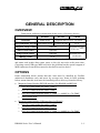
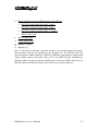
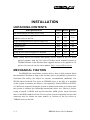
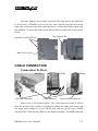
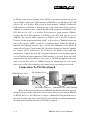
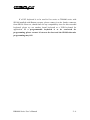
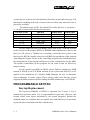
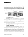
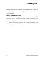
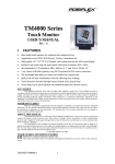
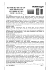
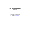
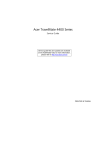
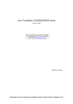
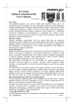
KB4000 / KP100 / SD100
MULTIFUNCTION
SECURITY DEVICE
USER’S MANUAL
Rev. B
MANUFACTURED BY: MUSTEK
CORP.
AN ISO-9001 AND ISO-14001
CERTIFIED MANUFACTURER
SOME IMPORTANT NOTES
FCC NOTES
This equipment generates, uses, and can radiate radio frequency energy and, if not installed
and used in accordance with the instructions manual, may cause interference to radio communications.
It has been tested and found to comply with limits for a Class A digital device pursuant to subpart J of
Part 15 of FCC Rules, which are designed to provide reasonable protection against interference when
operated in a commercial environment. Operation of this equipment in a residential area is likely to
cause interference in which case the user at his own expense will be required to take whatever
measures to correct the interference.
WARRANTY LIMITS
Warranty will terminate automatically when the machine is opened by any person other than
the authorized technicians. The user should consult his/her dealer for the problem happened. Warranty
voids if the user does not follow the instructions in application of this merchandise. The manufacturer
is by no means responsible for any damage or hazard caused by improper application.
The hardware utility program, including instructions for its use, is provided “AS IS” without
warranty of any kind. Mustek Corp. further disclaims all implied warranties including without
limitation any implied warranties of merchantability or of fitness for a particular purpose. the entire risk
arising out of the use or performance of the software and documentation remains with you.
ABOUT THIS MANUAL
This manual is written in an attempt with full strength to assist the user to utilize the stand
alone multifunction keyboard KB4000 series together with its derivative upgrade kits for the Posiflex
touch terminal systems. This series of products incorporate several delicately designed POS peripherals
each can be used as an excellent tool to accommodate the required security specially involved in POS
business, kiosk and hospitality operation. This manual covers both operational and technical aspects of
these units.
The manufacturer of the KB4000 series heartily apologizes to the user for reserving the right
to change or to modify this manual without notice due to the rapid and constant progress and
improvement on science and technology. The user may always obtain the most up to date information
through our web site: http://www.posiflex.com.tw .
© Copyright Mustek Corp. 2003
All rights are strictly reserved. No part of this documentation may be reproduced, stored in a
retrieval system, or transmitted in any form or by any means, electronic, mechanical, photocopying, or
otherwise, without the prior written consent of Mustek Corp. the publisher of this documentation.
TRADE MARKS AND SERVICE MARKS
POSIFLEX is a registered trademark of Mustek Corp..
Other brand and product names are trademarks and registered trademarks and service
marks of their respective owners.
P/N: 19010900030
GENERAL DESCRIPTION
OVERVIEW
Table below indicates construction of this series of security devices.
KB4000
KP100
SD100
Structure
Stand alone
Upgrade kit for Jiva (TP) series
Programmable keypad Horizontal layout Vertical layout
Magnetic stripe reader
Optional
Smart card reader
Optional
N. A.
Optional for one
of the two (Note)
Optional
Optional for one
of the two
N. A.
iButton reader
Note: In SD100, the internal control boards for standard USB interface MSR
and smart card reader share same space so they do not exist at the same time.
Choosing a non-USB type MSR can solve the problem but the special support of
MSR connector from the host must be checked for such a choice.
Finger print sensor
OPTIONS
Items underlined below means that this item must be installed by Posiflex
authorized distributor only and never by average user. Items in Italic printing
below means that this item must be installed prior to delivery from the factory.
•
•
Magnetic Stripe Reader (PS2 KB interface for KB4000 and KP100)
∗
ISO 7811 head reader for tracks 1 and 2
∗
ISO 7811 reader head for tracks 2 and 3
∗
ISO 7811 reader head for tracks 1, 2 and 3 + AAMVA + CA DMV
∗
JIS/II reader head
Magnetic Stripe Reader (USB interface for SD100)
∗
ISO 7811 head reader for tracks 1 and 2
∗
ISO 7811 reader head for tracks 2 and 3
∗
ISO 7811 reader head for tracks 1, 2 and 3 + AAMVA + CA DMV
KB4000 Series User’s Manual
1-1
•
Magnetic Stripe Reader (MSR interface for SD100)
∗
ISO 7811 head reader for tracks 1 and 2
∗
ISO 7811 reader head for tracks 2 and 3
∗
ISO 7811 reader head for tracks 1, 2 and 3
∗
JIS/II reader head
•
Smart card reader
•
Finger print sensor
•
iButton receptor
•
iButton key
Note: if all devices utilizing a specific interface are omitted from the product,
that interface will not be installed in the product. Ex. For SD100 with only
special interface MSR installed or KP100 or KB4000 containing no finger print
sensor neither smart card reader, there will be no USB interface installed; For
SD100 without the special interface MSR, there will be no MSR connector; For
SD100 without the iButton reader, there will be no 9 pin D connector.
KB4000 Series User’s Manual
1-2
INSTALLATION
UNPACKING CONTENTS
Items packed in for
KB4000 KP100 SD100
The multifunction security device itself
Yes
Yes
Yes
Screws to hold the upgrade kit to Jiva series or
No
Yes
Yes
TM4000 series or the like
24 pcs of transparent key caps for single key
Yes
Yes
No
1 pc of key clip
Yes
Yes
No
Legend sheets
Yes
Yes
No
This manual
Yes
Yes
Yes
Utility drivers stored in form of CD ROM
Yes
No
No
iButton key (only when iButton receptor installed)
No
No
2 pcs
Note: Utility drivers for KP100 and SD100 can be found in the CD ROM
packed together with the Jiva series Posiflex touch terminal system or
TM4000 monitor or the like that these upgrade kits are to be applied to. Or
please visit our web site for latest updates: http: www.posiflex.com.tw
MECHANICAL FIXATION
For KB4000 the stand alone security device, there is little concern about
the mechanical fixation as long as the security device (keyboard) is placed in a
horizontal flat surface not subject to extreme environmental conditions. For
SD100 ordered with the Jiva series or TM4000 series or the like, it is installed
on the system or monitor on delivery. For separately ordered SD100 or KP100,
it is delivered separately from the system or monitor and needs to be fixed onto
the system or monitor per following instructions before use. However, before
trying to install a SD100 with special interface MSR, please check first that
there is the MSR connector in the I/O area of the system or monitor because this
connector may be absent on some models or versions of the Jiva series or
TM4000 series or the like.
2-1
KB4000 Series User’s Manual
You may find two screw holes on back of the right side of the main unit
of Jiva series or TM4000 series or the like. Just align the upgrade unit on the
right edge of the main unit after removing these 2 screws then replace them with
the attached 2 screws and fasten them with washer as indicated in the picture
below.
The Upgrade Kit
Upgrade Unit Screw Hole
Back of Jiva Series
CABLE CONNECTION
Connection To Host
KB4000
PS/2 KB Connector
KP100
USB Connector
SD100
Special MSR Connector
Please refer to the pictures above. The USB connector could be absent
from the product if the product is purchased without the smart card reader and
the finger print scanner or if it is SD100 with only the special type of MSR
(instead of the USB interface MSR) or the iButton receptor. The MSR connector
KB4000 Series User’s Manual
2-2
in SD100 could also be missing if the SD100 is purchased without the special
type of MSR. Connect the USB connector of KB4000 to a USB hub or the USB
port in a PC or a Posiflex POS system or touch monitor TM4000. Connect the
USB connector of KP100 or SD100 to one of the USB ports of Jiva series or
TM4000 in connector area. Connect the PS/2 KB connector of KB4000 to the
PS/2 KB jack in a PC or a Posiflex POS system or touch monitor TM4000.
Connect the PS/2 KB connector of KP100 to the PS/2 KB jack in Jiva or
TM4000. The special MSR connector of SD100 is an 8 pin SIL connector.
Connect it to the connector marked “MSR” in Jiva series or TM4000 connection
area if this special “MSR” connector is supported there. When the SD100 is
installed with iButton receptor, there will be one additional 9 pin female D
connector and a pair of male/female PS/2 keyboard connectors from the upgrade
kit. Connect the D connector to the COM port for iButton setup (and data
connection). Connect the male PS/2 keyboard connector to the keyboard port in
Jiva or TM4000 for data connection if KB interface is selected. Route the cable
connection for KP100 or SD100 to Jiva series or TM4000 through the side of the
cable cover on Jiva series or TM4000. Break the obstructing side wall of the
cable cover in the cable entrance to the connector area according to the needs.
Connection To PS/2 Keyboard
KB4000 Rear View
KP100 Rear View
PS/2 KB Connector
Indentation For Cable Holding
Refer to the pictures of bottom of KB4000 and KP100 with their partially
enlarged pictures to the right above. In the cavity found at rear side of KB4000
or KP100, there is a PS/2 KB jack. Connect a standard PS/2 keyboard device to
this jack and insert the cable from the PS/2 keyboard device into the indentation
for strain relief and fixation when a PS/2 KB is required.
2-3
KB4000 Series User’s Manual
If a PS/2 keyboard is to be used in Jiva series or TM4000 series with
SD100 installed with iButton receptor, please connect it to the female connector
from SD100. However, should there be any compatibility issue for this cascaded
keyboard, please try use another brand keyboard or a USB keyboard for
application. If a programmable keyboard is to be connected for
programming, please connect it between the host and the SD100 otherwise
programming may fail.
KB4000 Series User’s Manual
2-4
OPERATION GUIDE
SMART CARD READER
Driver Installation
The smart card reader device driver has to be installed before this device
can be accessed by the application software. Please find the device driver from
the Posiflex Product Information CD ROM that comes alone with KB4000 or
the Jiva or TM4000 series that KP100 or SD100 is to be applied to. Please visit
our web site (http://www.posiflex.com.tw) for latest updates of such drivers.
FINGER PRINT SENSOR
The finger print sensor is connected to the system through USB interface.
The operating system must be capable to handle the USB interface to have this
device working. Starting the computer with the USB interface for this device
connected or inserting the USB interface of this device with the computer
running will activate the “Add New Hardware Wizard”. Follow the wizard and
find in the above mentioned CD ROM under subdirectory drivers and then
KB4000 or the main product KP100 or SD100 is applied to and then the
subdirectory for the finger print scanner when required.
Application Tips
The Posiflex finger print sensor has been tested to operate well on
reading finger prints of various skin conditions, it is still advisable to keep the
scanning area clean. To have a successful scanning, the finger must be placed in
a way that the core of the finger print is within the scanning area, the finger
should align with the sensing pad within a tolerance of +/- 15º and the finger
must get in touch with the drive ring around the scanning area. Place the finger
down flat, lightly but firmly on the sensor. Do not roll the finger as you might in
a traditional ink-and-paper finger print taking. Keep the finger flat and
motionless against the sensor detection surface for a couple of seconds during
the imaging process. Although the finger print patterns vary widely from type to
3-1
KB4000 Series User’s Manual
type, each finger print has a central area around which the remainder of the
pattern is distributed. This central area is the core of the finger print. Best
performance is achieved when the core of the finger print is placed in the center
of the sensor detection surface. It is essential to place the core of finger print
inside the sensor area to obtain a successful image capture of the finger print.
It is most advisable in real practice to register (enroll) for each ID more
than 1 finger and even better to register fingers from both hands into the system.
In this way, the identification procedure can less likely be obstructed even in
case of accidental injury. Please note that the finger print sensor is not suitable
for taking the finger print image of an infant.
Please refer to the readme files in the software installation for further
detail or consult our web site http://www.posiflex.com.tw
MAGNETIC STRIPE READER
The regular magnetic stripe reader in KP100 or KB4000 connects to the
host through KB port and therefore requires no driver installation to get it
working. The regular magnetic stripe reader in SD100 connects to the host
through USB port working as a USB KB and therefore also requires no driver
installation except setting up the USB keyboard to be enabled in system CMOS
setup. However for the special MSR type in SD100 that utilizes a MSR
connector, it relies on the controller inside the MSR port of the host to
consolidate the MSR data into KB port of the system.
Besides the interface options there are also reader head options applicable
to MSR in these security devices. The reader head can be JIS II type or one of
the possible configurations in ISO standard (tracks 1 & 2, 2 & 3, 1 & 2 & 3). For
ISO MSR, some parameters on data readout can be set by jumper setting or by
software provided by Posiflex as below. For MSR to read card of AAMVA and
CA DMV, the reader head must be 3 tracks ISO type and it must be on KB4000
or KP100 or it has to be the USB interface type in SD100.
12
To manipulate the ISO MSR
2
1
11
in
SD100,
one has to alter the jumper
CN2 CN1
CN3 JP1
settings on the controller board in the
U1
U5 U3
KB4000 Series User’s Manual
3-2
security device as drawn left with functions described in the table next page. The
function for enabling each track of course comes in effect only when the track is
physically available.
The default status of JP1 for normal ISO reader delivery is: pin pairs 12, 3-4 and 5-6 short while all the rest kept open.
Pin Pair in JP1
Function
When Short
When Open
1–2
Track 1
Enabled
Disabled
3–4
Track 2
Enabled
Disabled
5–6
Track 3
Enabled
Disabled
7–8
MSR Type
JIS II
ISO
9 – 10
Reserved
N.A.
N.A.
11 - 12
Leading / Stop Code
Disabled
Enabled
For ISO MSR in KP100 or KB4000, please find in the CD ROM attached
to the system for the product KP100 or KB4000 under subdirectory drivers and
then Jiva (TP series) or TM4000 etc. according to what the host system is and
then look for KP100 (usually referred to as KBM) for installation of the program
controlling the keypad. Please in the controlling program after installation enter
the configuration of the keypad and then access the configuration for the MSR.
The features controllable in this program are the same as that for SD100 by
jumper setting.
For the special type MSR in SD100, please find the subdirectory MSR
instead of SD100 in the CD ROM attached to the system that SD100 is to be
applied to for installation of a Posiflex MSR Manager for user to determine
some parameters in reader output. Please always make sure that the system
supports the MSR connector before finding the MSR subdirectory in CD ROM.
PROGRAMMABLE KEYPAD
Keytop Replacement
The keypad in KB4000 or KP100 is organized into 2 parts: a 4 by 4
numerical keypad area and a 4 by 6 programmable keypad area. However, this
keypad allows some layout alterations by the system integrator. Besides the
standard single key installed, there are double keys and blank keys for purchase
to provide more convenient interface with the user.
3-3
KB4000 Series User’s Manual
When replacement of keytop is required, it is advisable to use a flattop
(minus sign) screw driver (Do not use the attached key clip for this operation.)
to help getting the key top off gently. Please always first orientate the key tops
before inserting any keytop into the case of the keypad. Failure to do so could
result in permanent damage. Please always match the latching tab on bottom
stem of keytop with the tab in guiding hole and gently press the key top down
till a click sound is heard as indicated in the pictures below.
Double key top
Single key top
Tab in the
guide hole
Latching tab
Labeling On Keytop
The multifunction security device is provided with an easy and durable
method for reminding the user of content programmed in each programmable
key. First preprint (or write) in each cell of the attached colored legend sheet the
“name” for each key. Stick each cell to the corresponding keytop and then put
on the transparent key cap from the accessories. In this way, the labeling will be
protected and resistant to scratch or rubbing.
When re-labeling is required, please use the attached key clip to hook up
the transparent key cap and change the label then re-cap.
Content Programming
The programmable part of the keypad should either have been well
preprogrammed or be programmed in the software setup procedures if the
system integrator has arranged every thing well. Therefore, programming the
content for the keys on this keypad should be not required for end users. Even
if key content modification by end user is required, the software could provide a
handy programming tool in the software so that the system command keys will
not be wiped out. So the description on the programming utility supported by the
KB4000 Series User’s Manual
3-4
hardware manufacturer may be different from what actually made available for
the end user, it provides a basic idea on programming of the key pad.
To program the content of the keypad, please visit the manufacturer’s
web site described.
IBUTTON RECEPTOR
The iButton can be programmed to communicate on either RS232
interface or PS/2 KB interface through Hyper Terminal configuration setup.
Please refer to instruction on our web site for the detail. In general, this should
be taken care of by the software in the way organized by the system integrator.
Each iButton receptor is delivered with 2 iButton keys attached. Each
iButton key carries unique ID. Please approach your dealer for any additional
iButton key required.
3-5
KB4000 Series User’s Manual