1
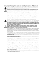
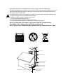
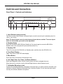
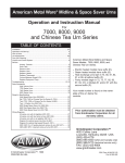
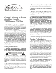
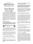
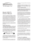
Important Safety Precautions and Explanation of Symbols
!
!
The exclamation point within an equilateral triangle is intended to alert the user to the presence of
important installation, operation, and service instructions in this manual.
The lightning flash with arrowhead symbol within an equilateral triangle is intended to alert the user
to the presence of uninsulated dangerous voltages within the enclosure that may be of sufficient
magnitude to constitute a risk of electrical shock to the user.
Please read this manual thoroughly before attempting to install, configure, or operate the Sherbourn
SR-8100. After successful installation and configuration of the SR-8100, be sure to retain this manual
in a safe place for future reference.
Safety is a key component to a long lasting and trouble free installation. Please read and follow
all instructions and heed all warnings on the SR-8100 and in this manual. The vast majority of the
subsequent safety precautions are common sense. If you are not comfortable with the installation
of audio/video entertainment equipment, you should seek the services of a qualified installation
professional or call us for help.
WARNING: To REDUCE the risk of fire or electric shock, do not use the
SR-8100 near water or in wet locations, do not expose it to rain or moisture,
DO NOT EXPOSE IT TO DRIPPING OR SPLASHING FROM OTHER SOURCES, AND ENSURE
THAT NO OBJECTS FILLED WITH LIQUIDS (SUCH AS VASES) ARE PLACED ON IT. Doing so
may result in damage to the SR-8100 and the risk of electric shock, which may
result in bodily injury or death.
WARNING: To reduce the risk of electric shock, do not remove the cover
from the SR-8100. There are no user-serviceable parts inside the SR-8100.
Refer all service to qualified service personnel.
Do not install the SR-8100 near or above any heat sources such as radiators, heating vents, or other
apparatus’ that produce heat. Do not block any ventilation openings or heat sinks. Avoid installing
the SR-8100 directly above other heat-producing equipment unless sufficient ventilation or forced-air
cooling is provided.
Do not install the SR-8100 in locations without proper ventilation. The SR-8100 should not be operated
on a bed, sofa, rug, or similar surface that may block vents. The SR-8100 should not be installed in an
enclosed location such as a bookcase, cabinet, or closed equipment rack unless sufficient forced-air
ventilation is provided.
Always install your SR-8100 according to the manufacturer’s instructions and only use attachments or
accessories specified by the manufacturer.
Do not install the SR-8100 on any stand, shelf, or other piece of furniture that is unable to support its
weight. If a cart is used to move the SR-8100, use caution to avoid injury from tip-over.
Connect the SR-8100 only to power sources of the correct voltage (as shown in this manual and on
the SR-8100).
Protect power supply cables from being pinched, walked on, or otherwise damaged. Be especially
careful where the power cable enters the power outlet and the SR-8100 unit.
Only connect the SR-8100 to an electrical outlet or extension cord of appropriate type and rating.
DO NOT defeat the safety purpose of a grounding or polarized plug by removing ground pins or using
unsafe adapters. A polarized plug has two blades - one wider than the other. A grounding plug has a
third ground prong in addition to the two main conductors. The wide blade or third grounding prong is
provided for your safety. If the provided plug does not fit your outlet, consult an electrician to replace
your obsolete outlet. If you replace the power cord on the SR-8100, only use one of similar type and
equal or greater current rating.
The power cable for the SR-8100 should be unplugged from the outlet during severe electrical storms,
or when unused for a long period of time.
!
Only replace the fuse(s) in the SR-8100 with a fuse(s) of proper value and voltage rating.
The SR-8100 should only be cleaned as directed in the manual. Avoid spraying liquids directly onto the
SR-8100 and NEVER spray liquids into the vents. Care should be taken so that small objects do not
fall into the inside of the SR-8100.
You should seek service for your SR-8100 by qualified service personnel if any of the following occur:
1. The power-supply cord or the plug has been damaged.
2. Objects or liquid have fallen or spilled into the vents.
3. The SR-8100 has been exposed to rain.
4. The SR-8100 exhibits a marked change in performance.
5. The SR-8100 has been dropped, or its enclosure or chassis is damaged.
NOTE: TO COMPLETELY DISCONNECT THE SR-8100 FROM THE AC POWER MAINS,
DISCONNECT THE AC POWER CORD FROM THE AC RECEPTACLE.
NOTE: THE SR-8100 AC POWER CORD MUST REMAIN READILY ACCESSIBLE AT ALL TIMES.
CAUTION
CAUTION: TO REDUCE THE RISK
OF ELECTRICAL SHOCK, DO
NOT REMOVE COVER. NO USER
SERVICEABLE PARTS INSIDE.
REFER SERVICING TO QUALIFIED
SERVICE PERSONNEL.
Ground clamp
Antenna lead-in wire
Antenna discharge unit
(NEC section 810-20)
Electric service
equipment
Grounding conductors
(NEC section 810-20)
Ground clamps
NEC - National Electrical Code
Power service grounding
electrode system
(NEC art 250, part H)
FCC Interference Statement
Note: This equipment has been tested and found to comply with the limits for a Class B digital
device, pursuant to Part 15 of the FCC rules. These limits are designed to provide reasonable
protection against harmful interference in a residential installation. This equipment generates,
uses and can radiate radio frequency energy and, if not installed and used in accordance with
the instructions, may cause harmful interference to radio communications. However, there is no
guarantee that the interference will not occur in a particular installation. If this equipment does
cause harmful interference to radio or television reception, which can be determined by turning the
equipment off and on, the user is encouraged to try to correct the interference by one or more of the
following measures:
Reorient or relocate the receiving antenna.
Increase the separation between the equipment and receiver.
Connect the equipment to an outlet on a circuit different from that of the receiver.
Consult the manufacturer or an experienced radio/TV technician for help.
For questions regarding service, please contact:
Sherbourn Technologies, Inc.
131 SE Parkway Court
Franklin, Tennessee
37064
Tel 1-877-366-8324
www.sherbourn.com
SR-8100: User Manual
SR-8100
7.1 Channel AV Receiver
Contents
Important Safety Precautions and Explanation of Symbols
The Sherbourn SR-8100.............................................................................2
About This Manual.......................................................................................2
Mechanical and Environmental...................................................................3
Features......................................................................................................4
Controls and Connectors.............................................................................5
Configuration and Operation.....................................................................18
Example Input Configuration.....................................................................46
Connectivity...............................................................................................47
Care and Maintenance..............................................................................48
Installing the Rack Mount Kit.....................................................................49
Troubleshooting.........................................................................................50
Sherbourn Technologies, LLC Limited Warranty.......................................51
Notes.........................................................................................................53
Page 1
SR-8100: User Manual
The Sherbourn SR-8100
Thank you for choosing the Sherbourn SR-8100 7.1 Channel Home Theater Receiver. The
SR-8100 combines incredibly fast, clean video switching, all the latest surround sound decoding
modes, true audiophile sound quality, an intuitive, easy to use menu structure, and seven channels
of superb quality amplification to give you the ultimate performance attainable today in a home
theater receiver.
The SR-8100 forms the perfect basis for an exceptional sounding home theater system. We’re
very proud of our achievement, and we trust you’ll enjoy listining to it as much as we’ve enjoyed
developing it.
Enjoy,
The Sherbourn Team
About This Manual
This manual will provide you with all the information you need to install and configure the SR-8100
to achieve its optimum potential. The manual also includes a brief summary of the features offered
by the SR-8100 and descriptions of how the controls work.
You may wish to record serial numbers or other purchase information on the Notes page at the back
of this manual.
Page 2
SR-8100: User Manual
Mechanical and Environmental
Dimensions:
17” wide x 4” high x 16.5” deep (includes feet, connectors, no rack kit);
22” wide x 8.5” high x 21” deep (boxed)
Weight: 25 lbs / 12 kg (unboxed); 34 lbs / 16 kg (boxed)
Rack mountable: Yes (rack mount kit included)
Power requirements:
115 VAC or 230 VAC +/- 10% @ 50 / 60 Hz (auto selected)
Ventilation and cooling:
To avoid overheating, be sure to provide adequate clearance and ventilation. You should provide a
minimum of 4 inches clearance on all sides of the SR-8100 (including the back). If the SR-8100 is to
be installed in an enclosed space, be sure to provide adequate ventilation or forced air cooling.
Page 3
SR-8100: User Manual
Features
The Sherbourn SR-8100 is a reference-caliber home theater receiver with high-performance
audio and video processing and seven channels of audiophile quality Class A/B amplification. The
SR-8100 provides plenty of audio and video inputs for most video enthusiasts, supports all the
latest surround sound decoding options, and delivers enough power to drive most speakers to
satisfying levels in a typical small-to-medium home theater. The SR-8100 includes the Sherbourn
Advanced Room Correction System™, which automatically calibrates your speakers and the rest
of your system to deliver clean and amazingly accurate sound with just a few simple commands.
If you prefer to configure your system manually, the SR-8100 also includes three separate banks
of powerful manual parametric equalization controls. Our sophisticated yet comprehensive menu
system even lets you compare your automatic and manual EQ curves to a flat target curve, and
choose the one you prefer with the touch of a button.
Some of the more important features of the SR-8100 include:
• 4 HDMI 1.4 inputs and one HDMI 1.4 output.
• Full support for 3D, CEC, and ARC.
• Xpressview™ HDMI switching for fast, clean input selection.
• High Definition Surround Sound with Twin Cirrus® 32-bit dual-core fixed-point DSP’s.
• Supports Dolby Digital, Dolby Digital EX, Dolby Digital Plus, Dolby TrueHD, Dolby Pro Logic IIx,
Dolby Pro Logic IIz, DTS, DTS ES, DTS HD, DTS HD Master Audio, DTS Neo:6, S/PDIF, PCM
8 channel (note: some audio formats are only supported via HDMI).
• Sherbourn Advanced Room Correction System™
(calibrated measurement microphone included).
• Flexible bass management, with selectable 12dB or 24 dB per octave crossover filters,
configurable in precise 5 Hz steps below 80 Hz (and 10 Hz steps above 80 Hz).
• Powerful parametric equalization provides exceptionally flexible manual control
(3 separate manual EQ banks; each has 11 bands per each main channel and 3 bands for sub).
• Separate 7.1 channel pure analog direct input for connecting SACD or other surround sources.
• Surround rear amplifier channels may be re-tasked to bi-amplify front channel speakers.
• Integrated Bluetooth 3.0 for CD quality audio from mobile devices with apt-X™.
• Zone 2 and Zone 3 audio support.
• A balanced subwoofer output (an XLR-to-RCA balanced-to-unbalanced adapter is included).
• Video-On-Standby sends audio and video to the display even when the SR-8100
is in standby mode.
• Last Video Memory allows viewing of one source while listening to another.
• High quality headphone amp included for private listening.
• Comprehensive control via full-color OSD (on screen display) over live video with adjustable
transparency.
• All adjustments are made in real time over live video and audio.
• Ergonomic custom remote control included.
• Sherbourn five year warranty.
You can find more information about the SR-8100 Home Theater Receiver on our website at
www.sherbourn.com.
Page 4
SR-8100: User Manual
Controls and Connectors
Front Panel - Controls and Indicators
1
2
3
4
5
6
7
8
9
1. Input Selector (rotary encoder)
Turn this to quickly select between configured inputs; once the correct input is selected, press it to
“lock in” your choice.
Note: The Input Selector can only select between inputs that are enabled. To access inputs
which are not enabled, you must use the Input Menu.
2. Standby Button
Press this to switch the SR-8100 from Standby to On; press it again to return the SR-8100 to
Standby mode. (The rear panel AC power switch must be On.)
3. Standby LED
This LED is red when the SR-8100 is in Standby mode, and blue when the SR-8100 is On.
4. Front Panel Display
Large, clear, easy to read VFD status display.
5. Menu Button
Press this button to activate the configuration menu.
6. Left, Right, Enter, Up, Down, and Return Buttons
When the configuration menu is active, these buttons are used to navigate the menu.
When the menu is not active, use the Left and Right buttons to select between inputs.
7. Calibration Microphone Jack
Connect the (included) calibration microphone to this jack when you wish to perform automatic room
calibration using the Sherbourn Advanced Room Correction System. For the most accurate results,
use only the included calibration microphone.
Page 5
SR-8100: User Manual
8. Headphone Jack
Connect any standard pair of stereo headphones for high-quality personal listening. When you plug
in a pair of headphones, the main volume is automatically muted.
9. Volume Control
The Volume Control on the SR-8100 is a rotary encoder that instructs the digitally controlled analog
resistor ladder network volume control. (The dot on the knob does not indicate the volume setting.)
Page 6
SR-8100: User Manual
Rear Panel
FM
AM
ANTENNAS
SUB OUT
SBL/SBR
SBL
ZONE 2
BACK CHNL
L
R
MIX
AN 1
L
AN 2
L
SL
R
AN 4
ZONE 2
AN 3
STEREO IN
R
FL
FR
SL
CNT
IN
FL
SBL
SBR
OUT
IR
SR
SUB
7.1 ANALOG IN
L
R
ZONE 3
1
CO 1
OPT1
2
TRIGGER OUT
7.1 OUT
CO 2
OPT2
DIGITAL IN
USB
CNT
HDMI 1
FR
HDMI 2
HDMI 3
SR
HDMI 4
HDMI OUT/ARC
RS232 CONTROL
SBR
220V
115V
Page 7
SR-8100: User Manual
Rear Panel - Control and Antenna Connections
AN 1
AN 2
AN 3
AN 4
FL
SL
CNT
SBL
220V
CO 1
L
RS232 CONTROL
HDMI 1
R
FM
OPT1
SUB OUT
SBL/SBR
ZONE 2
BACK CHNL
FR
STEREO IN
SR
SUB
7.1 ANALOG IN
IN
L
MIX
R
SBL
AM
115V
CO 2
L
ZONE 2
R
OUT
L
R
ZONE 3
SL
IR
HDMI 3
HDMI 4
HDMI OUT/ARC
DIGITAL IN
1
2
TRIGGER OUT
FL
USB
CNT
ANTENNAS
HDMI 2
OPT2
SBR
FR
SR
SBR
7.1 OUT
IN
FM
OUT
1
2
RS232 CONTROL
IR
TRIGGER OUT
AM
ANTENNAS
1
2
3
4
5
1. AM Antenna
Connect a standard AM antenna (included) to these terminals.
2. FM Antenna
Connect a standard FM antenna (included) to these terminals.
3. IR Remote Input and Output
Connect a remote IR detector (eye) to this input. This is especially useful if your SR-8100 is located
in a cabinet or other area where the front panel IR detector is blocked. Connect a remote IR
transmitter (“blaster”) to this output to control other equipment.
4. Trigger Outputs (2)
Connect each Trigger Output to one piece of trigger-enabled audio equipment. You can then
configure the SR-8100 to turn on specific trigger-enabled equipment when specific input sources are
selected.
5. RS-232 Serial Control
Connect this to the RS-232 serial output of a remote control device.
Page 8
SR-8100: User Manual
Rear Panel - Power Connections
AN 1
AN 2
AN 3
AN 4
FL
SL
CNT
SBL
220V
CO 1
L
RS232 CONTROL
HDMI 1
R
FM
OPT1
SUB OUT
SBL/SBR
ZONE 2
BACK CHNL
AM
115V
CO 2
FR
STEREO IN
SR
SUB
7.1 ANALOG IN
IN
L
MIX
SBL
R
L
ZONE 2
R
L
R
ZONE 3
SL
ANTENNAS
SBR
OUT
IR
HDMI 2
HDMI 3
HDMI 4
HDMI OUT/ARC
OPT2
DIGITAL IN
1
2
TRIGGER OUT
FL
USB
CNT
FR
SR
SBR
7.1 OUT
1
220V
115V
2
3
1. Input Voltage Indicator
The SR-8100 automatically detects the correct AC line voltage. These LEDs indicate which voltage
has been detected.
2. Power Switch
Switches the AC main power to the SR-8100 On and Off. When this switch is Off, the SR-8100 will
not respond to trigger signals or manual controls.
3. Standard IEC Power Inlet
The SR-8100 can be used with either a two-wire or three-wire standard IEC power cable.
Page 9
SR-8100: User Manual
Rear Panel - Video Inputs and Outputs (HDMI)
AN 1
AN 2
AN 3
AN 4
FL
SL
CNT
SBL
220V
CO 1
L
RS232 CONTROL
HDMI 1
R
FM
OPT1
SUB OUT
SBL/SBR
ZONE 2
BACK CHNL
AM
115V
CO 2
FR
STEREO IN
SR
SUB
7.1 ANALOG IN
IN
L
MIX
R
SBL
ANTENNAS
L
ZONE 2
SL
R
L
R
ZONE 3
SBR
OUT
IR
HDMI 2
HDMI 3
HDMI 4
HDMI OUT/ARC
OPT2
DIGITAL IN
1
2
TRIGGER OUT
FL
USB
CNT
FR
SR
SBR
7.1 OUT
HDMI 1
HDMI 2
HDMI 3
HDMI 4
1
HDMI OUT/ARC
2
1. HDMI Inputs (4)
Provide four inputs for components that have either HDMI or DVI-D outputs. (An appropriate
adapter will be required to connect DVI-D devices, and not all features will be available.) All four
HDMI inputs are identical, are HDMI 1.4 compatible, and support all standard formats (including 3D)
up to 1080p/24.
2. HDMI Output (1)
The HDMI output is HDMI 1.4 compliant, and is ARC and CEC enabled.
Page 10
SR-8100: User Manual
Rear Panel - Audio Inputs (Analog and Digital)
AN 1
AN 2
AN 3
AN 4
FL
SL
CNT
SBL
220V
CO 1
L
RS232 CONTROL
HDMI 1
R
FM
OPT1
SUB OUT
SBL/SBR
ZONE 2
BACK CHNL
FR
STEREO IN
SR
SUB
7.1 ANALOG IN
IN
L
MIX
R
L
ZONE 2
SBL
AM
115V
CO 2
R
SL
L
R
ZONE 3
SBR
OUT
IR
HDMI 3
HDMI 4
HDMI OUT/ARC
DIGITAL IN
1
2
TRIGGER OUT
FL
ANTENNAS
HDMI 2
OPT2
USB
CNT
FR
SR
SBR
7.1 OUT
AN 1
AN 2
AN 3
AN 4
FL
SL
CNT
SBL
L
R
STEREO IN
1
FR
SR
SUB
7.1 ANALOG IN
CO 1
CO 2
OPT1
OPT2
SBR
2
DIGITAL IN
3
1. Stereo Unbalanced Analog Audio Inputs (4 pairs)
Provide inputs for four unbalanced stereo analog sources.
2. 7.1 Unbalanced Analog Audio Inputs (1 set)
Provides one set of unbalanced 7.1 channel surround audio inputs. The signals received at these
inputs bypass all digital processing and are passed directly to the volume control and the preamp
outputs. Typically, the analog surround sound outputs of an SACD player or external decoder are
connected to these inputs.
3. Digital Audio Inputs
The SR-8100 provides four digital audio inputs. CO 1 and CO 2 are for standard Coaxial connectors
carrying S/PDIF digital audio; OPT 1 and OPT 2 are for standard Toslink optical cables carrying
optical S/PDIF digital audio.
Note: The USB input is only for use in applying firmware updates.
Page 11
SR-8100: User Manual
Rear Panel - Main Audio Outputs (Analog)
1
SUB OUT
AN 1
AN 2
AN 3
AN 4
FL
SL
CNT
SBL
220V
CO 1
L
RS232 CONTROL
HDMI 1
R
FM
OPT1
SUB OUT
SBL/SBR
ZONE 2
BACK CHNL
AM
SBL
115V
CO 2
FR
STEREO IN
SR
SUB
7.1 ANALOG IN
IN
L
MIX
R
L
ZONE 2
R
SL
SBR
OUT
L
R
ZONE 3
IR
HDMI 3
HDMI 4
HDMI OUT/ARC
DIGITAL IN
1
2
TRIGGER OUT
FL
USB
CNT
ANTENNAS
HDMI 2
OPT2
FR
SR
SBR
7.1 OUT
SBL
SL
FL
CNT
FR
SR
SBR
7.1 OUT
2
1. Subwoofer Output (balanced)
Connect this output to the balanced input of a powered subwoofer.
(An unbalanced subwoofer may be connected using the included XLR-to-RCA adapter.)
2. Speaker Outputs (7)
Connect up to seven 4 ohm or 8 ohm speakers to these outputs.
Note: The SR-8100 can be configured for either 5.1 or 7.1 surround sound operation.
If you configure the SR-8100 for 5.1 channel operation, use the FL, FR, CNT, SL, and SR
speaker outputs (and NOT the SBL and SBR outputs).
Note: These speaker outputs can also be configured as Front Left and Front Right Height
Speakers, or as Bi-Amped outputs for the front speakers.
Note: The SBL and SBR Speaker Outputs may be configured to run as a stereo pair of
speakers operated by Zone 2 (see the Zone Audio Outputs section for details).
Page 12
SR-8100: User Manual
Rear Panel - Zone and Mix Audio Outputs (Analog)
AN 1
AN 2
AN 3
AN 4
FL
SL
CNT
SBL
220V
CO 1
L
RS232 CONTROL
HDMI 1
R
FM
OPT1
SUB OUT
SBL/SBR
ZONE 2
BACK CHNL
FR
STEREO IN
SR
SUB
7.1 ANALOG IN
IN
L
MIX
R
L
SBL
AM
115V
CO 2
ZONE 2
R
L
R
ZONE 3
SL
SBR
OUT
IR
HDMI 3
HDMI 4
HDMI OUT/ARC
DIGITAL IN
1
2
TRIGGER OUT
FL
ANTENNAS
HDMI 2
OPT2
USB
CNT
FR
SR
SBR
7.1 OUT
SBL/SBR
ZONE 2
BACK CHNL
1
L
MIX
R
L
2
ZONE 2
R
3
L
R
ZONE 3
4
1. SBL/SBR Speaker Function Switch
When this button is pressed in, the speakers connected to the SBL and SBR speaker terminals
will act as Surround Back Left and Surround Back Right speakers (or as Front Left and Front Right
Height Speakers, or as Front Bi-Amp outputs, depending on how they are configured). When this
button is out, the speakers connected to the SBL and SBR speaker terminals will act as stereo
speakers for Zone 2. (This button setting overrides any other configuration settings.)
2. Mix Output
Provides a stereo unbalanced analog output that is the stereo mixdown of the surround sound
source currently playing in the main zone. The Mix Output is variable, and is controlled by the Main
Zone Volume setting.
3., 4. Zone 2 and Zone 3 Outputs
Provide stereo unbalanced line level analog audio outputs for Zone 2 and Zone 3.
Page 13
SR-8100: User Manual
Remote Control
HDMI 3
HDMI 4
B
ON/OFF
FREQ+
CH+
AM/FM
FREQ-
CH -
DIM
ENTER
TE
EXIT
+
Z2
+
VOL
-
Z3
B SUR
SUR
SUBTITLE
AUDIO
-
SUB
CEC
CTR
1. Standby Button
Press this button when the SR-8100 is On to return it
to Standby Mode.
2. Mode Buttons
12
13
14
15
MENU
AY
11
HDMI 2
INPUT
8
MODE
-
HDMI 1
PL
10
TV
MODE
+
DIS
5
6
7
8
9
STEREO
MU
4
DIRECT
UR
N
3
ON
RET
1
2
16
17
Press the Direct and Stereo Mode Buttons to switch
the SR-8100 directly into those audio modes. Press
the Mode + and Mode - Buttons to step through the
valid surround sound decoding modes available for
the input that is currently selected. (The modes you
can choose from will depend on the signal being
received at the input.)
Note: When playing DVD and Blu-Ray discs,
your player and the disc itself will probably offer
you a choice of several audio modes. After you
select one, the SR-8100 will determine which
type of audio is being supplied by your source
component, and will ONLY allow you to choose
audio modes that are compatible with that input
signal. (For example, if you select
“Dolby Digital” when playing a disc, the SR-8100
will offer you digital surround options compatible
with that mode, but NOT modes which are not
compatible with it.)
3. Direct Input Selector Buttons
PTR-101
Press one of the Direct Input Selector Buttons to
switch the SR-8100 directly to that input. The button
with the “B” symbol is used to select a Bluetooth
wireless device.
4. Tuner Control Buttons
Press the Tuner On/Off Button to switch directly to the
Tuner as your selected input; press it again to return
to your previously selected input. Use the AM/FM
Button to switch between the AM and FM bands. The
Freq+ and Freq- buttons change between different
AM or FM stations, and the CH+ and CH- buttons
step between any station presets you have created
(station presets are created in the Tuner Setup
menu).
Page 14
SR-8100: User Manual
5., 8. Return and Exit Navigation Buttons
Used to exit a screen or move up a level in some menus. (Refer to the hints along the bottom of the
OSD if you’re not sure which button to use in a given situation.)
6., 14. Enter Navigation Button and Navigation Ring
Use the Enter Button, and the Up, Down, Left, and Right controls on the Navigation Ring for
navigating the front panel and on-screen menus.
7. Display Button
Press this button to toggle the front panel display between displaying information about which input
is selected and displaying the current audio and video modes.
9. Input + and Input - Buttons
Press these buttons to step through the available inputs on your SR-8100.
10. Speaker Level Trim Controls
Use these buttons to temporarily adjust the levels of your various surround speakers. The changes
you make with these controls will not be retained when you turn the SR-8100 Off. You can
separately adjust the levels of the Center Channel, the Surrounds, the Back Surrounds, and the
Subwoofer with these controls.
11. CEC Control Buttons
These buttons are used to send commands from the SR-8100 to other CEC-enabled devices which
are connected to it. Various CEC-enabled devices will respond to some or all of these command
buttons when they are the selected input device. (You may also need to enable this feature on the
source device.) Please refer to the instructions that came with each device for details.
12. Menu Button
Accesses the front panel menu system and the full-color on-screen display (OSD).
13. Dim Button
Press this button to dim the front panel VFD (vacuum fluorescent display) on the SR-8100. The
display will get gradually brighter each time you press the button, then, when it reaches the brightest
setting, drop back to the dimmest setting (dim but not fully off).
15. Mute Button
Press this button to mute the audio output of the SR-8100; press it again to return to the previous
Volume level.
16. Volume Buttons
Press these buttons to turn the volume up or down on the SR-8100. The current volume setting is
displayed on the front panel display.
Page 15
SR-8100: User Manual
17. Zone 2 and Zone 3 Buttons
These buttons are used to control the audio being sent to the Zone 2 and Zone 3 outputs. When you
press the Zone 2 or Zone 3 button, the remote control will temporarily control that zone.
The display will switch to indicate that you are now controlling the selected zone; you may then
press the On or Standby buttons to turn the power for that zone On or Off (this includes the output
signal for that zone, and the trigger, if you have assigned one to that zone); you may use the Input
+ and Input - to step between inputs for that zone; and you may use the Vol + and Vol - buttons
to control the audio level for that zone. The remote control will return to normal mode (no longer
controlling the selected zone) a few seconds after you finish entering changes.
Note: The Volume and Input Selector Buttons will only accept changes while the zone you
are addressing is turned On. (When each zone is Off, the only command that it will recognize
is On.)
Page 16
SR-8100: User Manual
Zone Operation
SBL/SBR Speaker Function Switch
The SR-8100 has seven channels of audiophile quality Class A/B amplification. If the SR-8100
is configured as a 7.1 channel receiver, all seven channels are used to power the set of seven
surround sound speakers in the main zone. (Press the button IN to select this configuration.)
When the SR-8100 is in this configuration, the amplifier channels normally used for the rear
surround speakers may be reconfigured to serve as Front Height Speakers, or as duplicates of
the Front Main outputs for bi-amping your front main speakers. These options are discussed in the
appropriate Menu sections of this manual.
If the SR-8100 is configured as a 5.1 channel receiver, the two rear surround channels (Surround
Back Left and Surround Back Right) may instead be configured to power a stereo pair of speakers
in Zone 2. (Pop the button OUT to select this configuration.)
Note: The Zone 2 stereo analog line level audio output is active regardless of whether the
SBL/SBR speakers are assigned to Zone 2.
Analog and Digital Zone Functionality
Both Zone 2 and Zone 3 can be configured to play either the same program material as is selected
for the main zone, an independently chosen analog input source, or a radio station sourced from the
SR-8100’s internal tuner.
In addition, Zone 2 on the SR-8100 may be configured to play an entirely different digital audio
source. If an independent digital audio input is chosen for Zone 2, it must be chosen from amongst
Coax 1, Coax 2, Optical 1, or Optical 2 and may only be 2-channel PCM audio (it cannot be
surround digital audio). Zone 2 may also be configured to independently play content from the
integrated Bluetooth input.
Note: Once the SR-8100 is paired to a Bluetooth device, they will remain paired as long as
the SR-8100 is On, even if you change the selected input (if you switch back to the Bluetooth
input you will not have to re-pair the device).
Page 17
SR-8100: User Manual
Configuration and Operation
Configuring Inputs
The SR-8100 allows any input connector to be assigned to any input source using the Input Setup
configuration screen.
Menus
The SR-8100 is configured using a set of easy-to-use menus. When you first access the menu
system using either the Menu button on the SR-8100 front panel or the remote control, the menu will
open displaying one of the five main menu screens (Input, Mode, Parameter, Zone, or Setup).
Use the Left and Right navigation buttons (on the front panel or remote control) to move between
the different top menu screens. In most cases, pressing either the Down arrow key or Enter will
enter the menu page. The hints line at the bottom of the menu screen will always indicate which
keys are valid in your current context.
A small “down arrow” icon on the bottom right corner of the menu screen indicates that the menu is
longer than a single page. If so, pressing the Down arrow when you are on the bottom item on the
menu will move you to the second page of the menu.
Note: Operation of the SR-8100 is relatively straightforward, and screen hints are provided to
make navigation easier. If you are uncertain which navigation keys are active in your current
menu context, refer to the hints line at the bottom of the screen.
Page 18
SR-8100: User Manual
Menu Tree
MENU
Input
Mode
Input Config
Playback
Parameter
Tuner Setup
Input Setup
Remote
Hot Key
Zone
Speaker
Setup
Size /
Crossover
Setup
Auto
Room EQ
Noise Test
Option
Speaker
Distance
Load Default
Version
Page 19
LFE Level
SR-8100: User Manual
Input Menu
On the Input Menu, use the Up and Down navigation keys to choose an input; press Enter to select
the input (make it active).
Note: You will NOT be able to access inputs that are NOT Enabled on the
Setup / Input Config / Input Setup Submenu from this menu.
Note: If a video input source is already selected, and you then select an audio-only input
source, the previously selected video will continue to play along with the new audio.
Page 20
SR-8100: User Manual
Mode Menu
The Mode Menu will allow you to select which mode to use to decode your current input source.
The SR-8100 will normally select the “best” mode that is appropriate for the particular program
source you have selected. You may manually choose a different decoder mode - but will be limited
to those modes that are valid for the input format currently being received (for example, you cannot
choose Dolby Digital mode for an analog input signal).
By default, the SR-8100 will remember your choice, and will use it as the default choice the next
time an input signal of the same format is received. You may change this behavior using the
Setup / Playback Menu.
Page 21
SR-8100: User Manual
Parameter Menu
The Parameter Menu allows you to adjust several settings, including the levels of each set of
speakers. Changes made to speaker levels on this menu are temporary and will not be stored
when the SR-8100 is turned Off. If you wish to make changes to speaker levels that will be retained
between sessions, use the Setup / Speaker Setup / Noise Test Submenu.
Midnight Mode is a special audio mode with reduced dynamic range that is typically enabled to allow
listening late at night (the reduced dynamic range allows you to hear quiet dialogue without the loud
portions of the program being loud enough to disturb others).
Center Width and Center Distance alter the sound stage, and can be set to your personal
preference.
The Headphone Level is an offset which is applied to the main volume setting when you are using
headphones.
Changes made to the Center Width, Center Distance, Midnight Mode, and Headphone Level are
retained when the SR-8100 is turned Off.
Page 22
SR-8100: User Manual
Zone Menu
The Zone Menu is used to configure the additional audio zones (Zone 2 and Zone 3).
For each zone, the zone may be enabled (On) or disabled (Off), the default Volume level may be
set, and the default program source may be selected.
Either extra zone may be configured to play either the source currently selected in the main zone or
a different source, but not all choices are valid for both zones.
If either Zone 2 or Zone 3 is configured to Sync to Main, then that zone will play whatever source is
selected in the main zone regardless of the source format.
If Zone 2 is configured to play a different source, then the selected source must be either an analog
source, the tuner, a two-channel (PCM) digital source, or a Bluetooth source. Surround sound digital
sources are not valid in this context.
If Zone 3 is configured to play a different source, then the selected source must be an analog source
only.
Note: For the technically inclined; the SR-8100 has a second DAC, which can be used to
decode a second stereo digital audio source for output on Zone 2.
Note: There is a switch on the rear panel of the SR-8100 that allows you to route the Zone 2
audio to the amplifier channels normally used by the SR-8100 to deliver audio to the Rear
Surround Speakers. If this switch is IN, the SBL and SBR outputs are for Rear Surround
Speakers. If the switch is OUT, then the SBL and SBR outputs deliver Zone 2 audio.
This is a manual switch, and operates independently of the menu settings.
Page 23
SR-8100: User Manual
Setup Menu (main setup menu)
The Setup Menu is used to access most of the configuration options on the SR-8100.
Page 24
SR-8100: User Manual
Setup / Input Config Submenu
The Setup / Input Configuration Submenu is used to access most of the configuration options on the
SR-8100 related to input selections and configuration of the hot keys on the remote control.
Trigger 1 Mode and Trigger 2 Mode allow you to configure whether each trigger is activated by
specific inputs or specific zones. If either is configured to Input Set, then you will be offered the
option, when configuring each input, to decide whether that input will activate the trigger.
Page 25
SR-8100: User Manual
Setup / Input Config / Tuner Setup Submenu
The Setup / Input Configuration / Tuner Setup Submenu is used to configure the tuner settings and
memory presets for the SR-8100.
Page 26
SR-8100: User Manual
Setup / Input Config / Input Setup Submenu
The Setup / Input Configuration / Input Setup Submenu is used to configure various parameters
for each input on the SR-8100, including the audio and video source for each, the input name, an
individual audio input trim level for each input, an individual LipSync delay time for each input, and
which triggers are activated when the input is chosen.
Note: When the video source for an input is set to one of the HDMI inputs on the SR-8100,
selecting HDMI as the audio source will automaticaly select the audio input from the same
HDMI input as the video input.
Note: When an input is assigned to a hot key, that hot key will be indicated here. You will
NOT be permitted to disable an input that is assigned to a hot key until you delete the
hot key assignment for that input on the the Setup / Input Configuration / Remote Hot Key
Submenu.
Page 27
SR-8100: User Manual
Setup / Input Config / Remote Hot Key Submenu
The Setup / Input Configuration / Remote Hot Key Submenu is used to configure which input is
associated with which hot key on the remote control. The Bluetooth hot key (the one with the “B”
symbol) is pre-configured and cannot be changed.
Page 28
SR-8100: User Manual
Setup / Playback Submenu
The Setup / Playback Submenu allows you to configure which decoder mode is used by default to
decode each different type of source signal. Here you can configure which default mode the
SR-8100 will use to decode each type of input source when it is received. If you set any of these to
Last Used, then the SR-8100 will use the last mode you manually selected to decode this particular
type of input signal as its default mode for that type.
Page 29
SR-8100: User Manual
Setup / Speaker Setup Submenu
The Setup / Speaker Setup Submenu allows you to access the menus on the SR-8100 for
configuring speaker sizes and crossovers, levels, and distances.
Note: The Sherbourn Advanced Room Correction System will automatically select optimal
values for the size, crossover point, distance, and level of each speaker. These controls are
provided for users who either prefer to make their own adjustments using a sound level
meter or real time analyzer, or who wish to make “fine tuning” adjustments to the results of
the automatic room correction.
Note: If the Back Channel switch on the rear of the SR-8100 is OUT, then the SBL and
SBR Speaker Outputs will provide audio from Zone 2. If that switch is IN, then the content
provided by those speakers will be controlled by the SR-8100’s configuration menus.
If the Back Channel switch on the rear of the SR-8100 is IN, and Front Bi-Wire is set to On
in this menu, then those outputs will duplicate the Front Left and Front Right Main Speaker
Outputs and can be used to “vertically bi-amp” your front speakers (this menu setting takes
priority over other menu settings, but not the rear panel switch).
If the Back Channel switch on the rear of the SR-8100 is IN, and Front Bi-Wire is set to Off in
this menu, then the SBL and SBR speakers will be assigned to EITHER Surround Back Left
and Surround Back Right, OR FvH (front vertical height) speakers, depending on the setting
in the Setup / Speaker Setup / Size & Crossover Submenu.
Page 30
SR-8100: User Manual
Setup / Speaker Setup / Size & Crossover Submenu
The Setup / Speaker Setup / Size & Crossover Submenu allows you to configure the speaker size
for each set of speakers (Small or Large). For speakers set to Small, you may then configure a
crossover point and crossover slope for each set.
If FvH is set to Large or Small, then the SBL and SBR Main Speaker Outputs will be assigned as
Front Vertical Height speakers. If FvH is set to None, then the SBL and SBR Main Speaker Outputs
will be assigned as Surround Back Left and Surround Back Right Speakers.
Page 31
SR-8100: User Manual
Enhanced Bass is a special function intended to enhance the bass capabilities of systems with both
Large front speakers and a subwoofer. When enhanced Bass is set to On, bass frequencies from
the front channels are also sent to the subwoofer (even if the front speakers are set to Large).
Note: To configure the SR-8100 as a “regular 7.1 channel receiver”, the Back Channel switch
on the rear panel of the SR-8100 should be IN, Front Bi-Wire in the The Setup / Speaker Setup
Submenu should be set to OFF, and FvH in the Setup / Speaker Setup / Size & Crossover
Submenu should be set to NONE.
Note: If the Back Channel switch on the rear panel of the SR-8100 is in the OUT position,
then the SBL and SBR amplifier channels will be assigned to Zone 2. If you do NOT configure
both Back L/R and FvH Speakers to None in this menu, when the Back Channel switch is in
the OUT position, rear surround or front height content will be discarded.
Page 32
SR-8100: User Manual
Setup / Speaker Setup / Noise Test Submenu
The Setup / Speaker Setup / Noise Test Submenu allows you manually adjust (trim) the level for
each speaker individually. As each speaker is selected, a test tone (modified pink noise) is played
from that speaker.
These controls may be used simply to apply a minor adjustment to one or more speakers “by ear”.
You may also use a sound level meter or real time audio analyzer to match the levels of each of
your speakers.
Note: Unlike level changes configured in the Parameters Menu, changes made in the
Setup / Speaker Setup / Noise Test Submenu remain in effect when the SR-8100 is turned Off.
Page 33
SR-8100: User Manual
Setup / Speaker Setup / Speaker Distance Submenu
The Setup / Speaker Setup / Speaker Distance Submenu allows you manually adjust the distance
from each speaker to your chosen seating position.
Note: If your preferred seating area is large, measure the distance from each speaker to the
center of the overall listening area. It is usually preferable to arrange your listening room so
the speakers are symmetrical (so the distances from the left and right speakers of each set
to the listening position are equal).
Note: The Sherbourn Advanced Room Correction System will fill in these values for you
when you run it. Because a variety of factors may adversely affect the results of the
automatic calibration measurements, we suggest that you manually correct any distance
readings that are obviously incorrect.
Page 34
SR-8100: User Manual
Setup / Speaker Setup / LFE Level Submenu
The Setup / Speaker Setup / LFE Level Submenu allows you manually trim the subwoofer LFE
level for each different type of input signal. (You could use this adjustment, for example, to set the
subwoofer to play 1 dB quieter for all Dolby Digital movies, and 3 dB quieter for all 7.1 channel
analog inputs.) The range of these trim controls is from 0 dB to -10 dB.
Page 35
SR-8100: User Manual
Setup / Auto Room EQ Submenu
The Setup / Auto Room EQ Submenu is used to initiate the Sherbourn Advanced Room Correction
System, and to select which equalization curve is in effect.
When the Sherbourn Advanced Room Correction System is run, it will create and save one room
equalization curve. In addition, you may manually create up to three additional room equalization
curves.
To run the Sherbourn Advanced Room Correction System, plug the calibrated microphone into the
Cal jack on the front panel of the SR-8100, select Auto Room/EQ on the menu, and press Enter.
Follow the onscreen prompts until the cailbration procedure is complete.
Once the Sherbourn Advanced Room Correction System has been run, you will be able to choose
between the results of your automatic room calibration (Auto EQ), up to three manually entered
calibration curves (Manual EQ 1, Manual EQ 2, and Manual EQ 3), and Flat (no equalization).
Note: After you run the Sherbourn Advanced Room Correction System, the EQ settings it
generates will be automaticaly selected as the current default EQ.
You will be able to preview what each EQ choice sounds like by moving the highlight over each
and pressing Enter. When you exit this screen by pressing Return, the EQ bank you currently have
selected will become the active default EQ bank for the SR-8100.
Pressing Enter a second time (when the selector is on the choice that is already active) will bring
you to the EQ Setup Submenu for that particular EQ bank (where you will be able to adjust the
actual EQ settings for that choice).
Page 36
SR-8100: User Manual
Sherbourn Advanced Room Correction System™
The Sherbourn Advanced Room Correction System sends a series of test signals through your
speakers, measures the results with the (included) calibrated microphone, and configures the
SR-8100 to make your system sound its best. Even though the actual operation of the Sherbourn
Advanced Room Correction System is very sophisticated, it is very simple to use and will deliver
excellent results without manual tweaking in most situations. (The Sherbourn Advanced Room
Correction System also allows you to fine tune the settings and calibration curves it generates after
you run it, and to create your own manual calibration curves. You should also bear in mind that
the choices the Sherbourn Advanced Room Correction System makes may not agree with your
musical tastes; if so, then you should always go with what you prefer, and adjust your EQ settings
accordingly.)
First, unpack your calibration microphone, unwind the wire, and plug it into the Cal jack on the front
panel of the SR-8100. (The SR-8100 is calibrated for this particular microphone, so don’t use a
different one.)
Note: The Sherbourn Advanced Room Correction System will not start if the microphone is
not plugged in.
Second, place the microphone in your listening location. While the Sherbourn Advanced Room
Correction System will do its best to optimize the sound for your entire room, the calibration curve
and settings it generates will still be the most precise at the position where the microphone was
positioned when the calibration was carried out. The microphone should be placed where your head
is normally located.
Here are some tips for best results:
• The test will take several minutes, and some of the test tones are annoying, so you might want
to take pets or children out of the room (especially if they are noisy).
• Position the microphone close to where your head or ears normally are (on top of the back seat
cushion of your favorite chair or couch or, ideally, attached to a stand or tripod).
• The microphone is normally positioned with the point up (and the flat base down).
• Do not place the microphone in a location where it is blocked from a direct line-of-sight to
any speaker (like on a chair seat). If the microphone cannot “hear” a particular speaker, the
Sherbourn Advanced Room Correction System will raise the level of that speaker so it presents
a balanced sound at the position of the microphone, which will probably result in that speaker
being too loud for everyone else.
• Try to avoid flat reflective surfaces. If you must place the microphone on a table or other
reflective surface, place a towel or blanket under it to minimize reflections.
• Turn off any air conditioners or other gadgets that make noise, and avoid talking or making
noise during the test. Also turn off or remove from the area any telephones that are likely to ring.
If you live in a high traffic area, or have noisy neighbors, for best results wait for a quiet time of
day to run the Sherbourn Advanced Room Correction System. (If anything makes noise during
the test, it will throw off the results, and you’ll have to run Sherbourn Advanced Room Correction
over again for best results.)
• Avoid moving around the room during the test. It’s best if you pick a spot that doesn’t block
or change the sound field to stand or sit while the test is running. The best place is in the rear
of the room towards the center of the wall. Avoid walking near the microphone during the test
(even if you don’t block any speakers) because reflections from your body will interfere with the
accuracy of the results. And, of course, avoid making noise during the test.
Page 37
SR-8100: User Manual
•
If you rearrange your furniture, move your speakers, or add or remove reflective or sound
absorbing wall hangings (like big pictures or tapestries), you should re-run the Sherbourn
Advanced Room Correction System for best results.
• If you purchase new speakers, or change adjustments on your speakers or other equipment
(like the level controls on your tweeters or amps), you should run the Sherbourn Advanced
Room Correction System again.
• The Sherbourn Advanced Room Correction System is powerful, but you will still get the best
results if you start out with a good room layout and good speakers. At a minimum, try to position
speakers as symmetrically as possible from left to right relative to the listening position. (Left
and right speakers of each set should be about the same distance to the sides of the listening
position; the center should be as near the center as possible. Perfect symmetry may not be
possible in your listening room, but the closer you get, the better your results will be.)
• In general, highly reflective rooms are not optimum in terms of sound quality, and even the
Sherbourn Advanced Room Correction System may not be able to completely correct for the
acoustic properties of an overly “live” room.
Third, run the Sherbourn Advanced Room Correction System.
To run the Sherbourn Advanced Room Correction System, press the Menu button (to get into the
menu system), select Setup, move down to Auto Room EQ, move right to Auto Room EQ, and press
Enter. Press Enter again when asked, and again when asked after passing ambient level check. (If
you “fail ambient” it means that the Sherbourn Advanced Room Correction System thinks your room
is too noisy, so look for appliances or other things making noise and quiet them.)
Note: If the Sherbourn Advanced Room Correction System fails to run, ensure that your
microphone is plugged in to the correct input (the Cal jack on the front of the SR-8100).
The Sherbourn Advanced Room Correction System will now play a series of test tones through each
of your speakers in turn. This will take several minutes; do not interrupt the sequence. If you don’t
have a full seven speakers plus a subwoofer, the Sherbourn Advanced Room Correction System will
still take several seconds to “test” each of the ones that aren’t there (to verify that they really aren’t
there); don’t worry, the Sherbourn Advanced Room Correction System won’t get stuck. After the first
series of test tones are done, the Sherbourn Advanced Room Correction System will present you
with a screen summarizing what it has found out so far (the presence, distance, and phase of each
of your speakers) and wait for you to press Enter (it will eventually continue by itself if you do not).
Note: The Sherbourn Advanced Room Correction System is very sophisticated, but no
automated system is totally foolproof. Unusual room acoustics, reflections, or unusual
speakers can cause it to get incorrect results. If the Sherbourn Advanced Room Correction
System says that the phase of a particular speaker is reversed, it is a good idea to double
check your wiring, and the phase of your power amp and speaker. If, however, you find that
the Sherbourn Advanced Room Correction System is mistaken, you can safely ignore its
findings. If the Sherbourn Advanced Room Correction System says your subwoofer is out
of phase, look for a phase reversal switch on your sub (many have one) and try it the other
way. If your sub has a variable phase control, setting it to “180” is the same as reversing the
phase. Moving a subwoofer to a different position in the room may also result in a reversed
acoustic phase. If your sub is definitely phased correctly, or you have no way to reverse
it, then just ignore that as well. If you change any wiring or speaker positions at this point,
please cancel out of the Sherbourn Advanced Room Correction System and restart it from
the beginning.
Page 38
SR-8100: User Manual
Notes (about setting subwoofers):
Since the Sherbourn Advanced Room Correction is controlling the bass management for
your subwoofer, it is usually optimum to set your sub itself to “flat”. If your subwoofer has a
phase setting, you should set it to “0 degrees” or “normal” (and not “inverted”). If your sub
has a built-in crossover that cannot be disabled, then set it to the highest allowed crossover
point. If your sub has a level control, setting it to a center position, or “0 dB”, is a good
place to start. If your subwoofer has special features for eliminating room nodes, or if you
are using bass traps or other advanced room correction devices, these adjustments should
usually be made BEFORE running the Sherbourn Advanced Room Correction System for
best results.
Once you have finished viewing the information presented by the Sherbourn Advanced Room
Correction System, press Enter to continue. The Sherbourn Advanced Room Correction System will
now play another series of test tones through each speaker. These tones are used to make more
precise measurements for each speaker (which will be used to generate the calibration settings).
After this series of test tones are done, the Sherbourn Advanced Room Correction System will
present you with another screen of information.
This time you will be prompted to SAVE the information by pressing Enter.
The fourth, and final, step to running the Sherbourn Advanced Room Correction System is to
activate the calibration settings that Sherbourn Advanced Room Correction has created. On the
current Menu screen, you can see the equalization settings that are currently applied by the
SR-8100. The options include Auto EQ, Manual EQ 1, Manual EQ 2, Manual EQ 3, and Flat. By
moving the highlight to each choice and pressing Enter, you change the current setting to that
choice (and may hear what it sounds like). The highlighted option is the one that is currently
selected. (The Auto EQ settings will be highlighted and selected by default.)
You will be able to go back later and change your choice, and to manually adjust the settings made
by the Sherbourn Advanced Room Correction System if you prefer. You may also create up to three
full sets of custom manual EQ setting and choose between them. To make the calibration curve
generated by your new Sherbourn Advanced Room Correction System active, and apply it to your
inputs, you must leave Auto EQ selected as the active EQ choice.
Note: Moving the selector bar to an EQ choice that isn’t highlighted and pressing Enter
selects that choice. At this point (if you have an active input which is subject to EQ) you will
be able to preview what that choice sounds like. Moving the selector bar to an EQ choice that
is already highlighted, and pressing Enter, takes you into a sub-menu where you can make
detailed adjustments to the selected EQ configuration. (If you get into this screen by mistake,
and want to get out without changing anything, you can do so by pressing Enter or Return.)
Note: If you have Direct Mode selected, or are using the 7.1 Channel Audio direct input, you
will NOT be able to preview the EQ settings (because EQ is not applied in Direct mode). It
is therefore a good idea to make sure that you are listening to an input and mode in which
EQ is applied if you want to preview your settings. (If you haven’t done any advanced
configuration, HDMI 1 or HDMI 2 will probably work well for this.)
Note: If you run the Sherbourn Advanced Room Correction System multiple times, you will
get similar results (but probably not identical). You will not get more accurate results by
running it repeatedly (it does not save or average results from multiple runs). If you aren’t
entirely satisfied with the results, try moving the microphone to a slightly different position,
or simply adjust the results manually to fit your tastes.
Page 39
SR-8100: User Manual
The Sherbourn Advanced Room Correction System™: How it works.
For the technically inclined, here is a brief explanation of how the Sherbourn Advanced Room
Correction System works:
The first set of tones you hear (the ones that get progressively louder) are used to set an
appropriate level at which to run the test.
The next set of tones are used to determine the individual level, phase, and distance of each
speaker. This is done three times, and the results averaged, to minimize errors.
The results are then displayed.
The next set of tones are used to determine the optimum EQ settings. First, a loud set of tones
is run, and the highest response peaks are reduced. The subsequent tests, which may be run
anywhere from two to five times depending on how much adjustment of the initial rough curve
is necessary, are basically repeats of the initial run. For each run, the result is averaged and
compared to the reference (flat) curve, and each time this is done, the response peaks are again
reduced, bringing the final result closer to the reference curve each time. Once the curve is as close
as possible to the reference curve, then the final offset and level calibration measurements are
performed.
The final sequence starts off with a loud burst of unequalized test signal, followed by a quieter burst
of the test signal with the calculated EQ applied. The third burst consists of the difference between
these two signals, and is used to detect any unaddressed room modes (nulls), which are then the
subject of further adjustments. The final loud burst is the equalized and adjusted test signal, and is
used to set the final, precisely calibrated, level trims for each channel.
The final results are then displayed, and you are prompted to save them.
Note: The results displayed by the Sherbourn Advanced Room Correction System
are provided to give you general insight into the areas where corrections have been
implemented, and the frequency bands and ranges which are affected by those corrections,
and should not be interpreted to literally represent the correction curve itself. The details of
the full calibration process, and the resulting correction curves, are far more complex.
The values provided are actually representative of the general offset values used to
apply the corrections, and so adjusting them will produce a corresponding change in the
correction curve (so you can, for example, increase the boost or cut in a particular band by
adjusting the corresponding value in the Sherbourn Advanced Room Correction System
configuration), but they should not be interpreted as representing the entirety of the
correction that is applied, and CANNOT be copied into a Manual EQ configuration memory to
produce a Manual EQ setting similar to the Auto EQ results. Setting all values in the Auto EQ
memory bank to their flat values also will NOT result in a flat response curve.
Page 40
SR-8100: User Manual
Setup / EQ Submenus (Auto / Manual 1 / Manual 2 / Manual 3)
The Setup / EQ Submenus are used to manually configure the parametric equalizers in the
SR-8100. The SR-8100 offers three separate “EQ banks” - named Manual 1, Manual 2, and
Manual 3. For each of the three Manual EQ banks, you can configure separate EQ settings for each
individual channel (speaker). The main channels each provide 11 bands of parametric equalization,
and the subwoofer channels each provide 3 bands.
The screens above show the EQ settings available for one channel (Front Left) in one of the Manual
EQ banks (Manual EQ 1). Use the Left and Right navigation buttons to navigate between screens
(to show the EQ screen for another channel in the same EQ bank), use the Up and Down navigation
buttons to move between individual EQ frequency bands for that channel, and use the Left and
Right navigation buttons to move between the Center Frequency (Fc), Gain, and Q settings for that
band.
Page 41
SR-8100: User Manual
WIth the old style “graphic equalizer”, you were given ten (usually) separate frequency controls,
each of which worked like a tone control (you could turn that band either up or down in level). A
parametric equalizer is infinitely more flexible. For each channel in each EQ bank you are given
eleven control bands. For each control band, you may choose the center frequency (Fc), how
narrow or wide a range of frequencies is affected (Q), and then finally the level for that band.
For example, to boost a wide range of frequencies in the lower voice range, you might set one band
to a Center Frequency of 600 Hz, and a Q of 0.5 (higher Q numbers mean narrower bands). At that
point you could use the Gain slider for that band to turn those frequencies up. To reduce a sharp
resonance around 33 Hz, you might set another band to a Center Frequency of 33 Hz, and a Q of 7,
and then set the Gain slider for that band to -6 dB.
Each PEQ frequency band can be set over the full range of audio frequencies, the Q for each
can be set between 0.25 (very gradual) and 24 (very sharp), and the gain of each ban can be set
anywhere between +3 dB and - 15 dB.
Note: The Auto EQ bank shows the EQ settings automatically entered by the Sherbourn
Automatic Room Correction system. However, Sherbourn Advanced Room Correction makes
other changes and settings that are NOT visible on this screen. While you may raise or lower
the Gain settings of specific bands on this screen to alter the automatic settings, setting all
bands to flat on this screen will NOT result in a flat response curve, and copying the settings
on this screen into a Manual EQ screen will NOT produce an equivalent response curve in
that Manual EQ bank.
Page 42
SR-8100: User Manual
Setup / Option Submenu
The Setup / Options Submenu is used to configure the CEC control options, OSD display options,
and Video on Standby feature on the SR-8100.
The OSD Depth setting configures the opacity for the Popup OSD menu.
The OSD Pop Up setting configures whether the main OSD Popup Menu is active or not
(the small popup that momentarily displays sample rate and decoder status cannot be disabled).
HDMI Audio Output configures whether the audio output of the SR-8100 is active (set this to
Amplifier if you want the SR-8100 to handle your audio).
Standby Video enables the Video on Standby function, which allows the SR-8100 to continue to
pass video and audio to your monitor even when it is in Standby mode.
The SR-8100 also offers several different levels of CEC control - which helps allow you to configure
the optimum amount of interaction between the SR-8100 and other CEC-enabled components. The
functions available with CEC control will depend on both the SR-8100 and your source components
and monitor, and you may be required to enable or configure CEC settings on your source
components.
Set HDMI CEC Control On to enable the CEC buttons on the remote control to control your DVD or
Blu-Ray player.
Set CEC Auto Source On to enable CEC commands to be passed between the chosen input device
and the SR-8100 (the SR-8100 will automatically come on when you turn your source component
on, and your source component will automatically come on when it is selected on the SR-8100).
CEC PWR Control will enable your SR-8100 and other components to switch each other on and off
(so, for example, your TV will come on when you turn on the SR-8100).
Page 43
SR-8100: User Manual
Setup / Load Default Submenu
The Setup / Load Default Submenu is used to return the SR-8100 to factory default settings (and is
also used to clear the SR-8100’s data and configuration buffers after a firmware update).
Selecting Load Default and confirming the action will delete ALL user configuration settings from the
SR-8100 and return it to the configuration it had when received from the factory.
Page 44
SR-8100: User Manual
Setup / Version Submenu
The Setup / Version Submenu displays the versions of the various firmware modules in the
SR-8100.
Page 45
SR-8100: User Manual
Example Input Configuration
The following is an example of how you might choose to configure your SR-8100. In the example,
we will be configuring a typical 7.1 surround system, with seven speakers and a powered sub, and
a Blu-Ray player and Cable Box as the video and audio sources. The Cable Box is connected to
HDMI 1 input, and the Blu-Ray player is connected to the HDMI 2 input. Both input devices, and our
monitor, support HD.
Electrical Connections
• Connect the Cable Box to the HDMI 1 Input (using an HDMI cable).
• Connect the Blu-Ray Player to the HDMI 2 Input (using an HDMI cable).
• Connect the Monitor (TV) to the HDMI Output (using an HDMI cable).
• Connect the amplifier outputs on the SR-8100 to your seven surround-sound speakers.
• Ensure that the Back Channel switch on the rear of the SR-8100 is IN.
• Connect the subwoofer output to your powered subwoofer.
Since the SR-8100 will be doing the bass management for all of our speakers, we have set
the crossover on our powered subwoofer to “Flat”. We have initially set the level on our
subwoofer to “0 db”.
Menu Settings
Note: In this example, we will be leaving a lot of settings at their default values, and will not
be entering several menu screens at all. Obviously, this is an example, and your system may
require different settings.
The only configuration that will be required to start enjoying your SR-8100 at this point is to run the
Sherbourn Advanced Room Equalization System (refer to Page 36 for details).
(You may even skip this step if you don’t want to take the time right now, or are still finalizing your
room setup. If so, then simply select HDMI 1 for Cable or HDMI 2 for your Blu-Ray player.)
Page 46
SR-8100: User Manual
Connectivity
•
•
•
•
•
•
•
•
•
•
•
•
•
•
•
•
•
4 – HDMI 1.4 inputs with 3D and CEC support.
1 – HDMI 1.4 output with ARC support.
4 – Line inputs (unbalanced, stereo).
1 – 7.1 channel input (7 channels plus sub, unbalanced).
1 – Integrated Bluetooth receiver.
2 – zone audio outputs (unbalanced, stereo).
1 – audio out (mix out, unbalanced, stereo).
4 – digital audio inputs (2 - optical Toslink; 2 - coax).
1 – USB input for SW upgrade only.
2 – Antenna inputs, AM and FM.
2 – Trigger outputs.
1 – IR remote input.
1 – IR remote output.
1 – RS-232 serial control input.
1 – Balanced subwoofer output (includes XLR-to-RCA balanced to unbalanced adapter).
7 – Speaker outputs (4 ohms / 8 ohms) gold plated 5-way binding posts.
1 – Remote control with CEC control panel.
Page 47
SR-8100: User Manual
Care and Maintenance
Periodic Maintenance
Your SR-8100 requires no periodic maintenance or calibration.
Cleaning your SR-8100
•
•
If necessary, the SR-8100 should be cleaned gently with a soft rag.
If something sticky gets on the front panel or case of the SR-8100, it should be cleaned with a
mild cleaning solution applied to a soft rag, followed by wiping with a clean rag dampened with
plain water and drying with a soft dry rag or cloth.
Note: DO NOT spray water or cleaning solution directly onto the SR-8100 or into
the vents.
• If something sticky gets on the remote control, it should be cleaned with a mild cleaning solution
applied to a soft rag, followed by wiping with a clean rag dampened with plain water and drying
with a soft dry rag or cloth.
Note: DO NOT submerge the remote control in liquid or spray water or cleaning solution
directly onto it.
Page 48
SR-8100: User Manual
Installing the Rack Mount Kit
SR-8100
Top
REMOVE
THESE
SCREWS
SR-8100
Right
Side
The SR-8100 includes a rack mount kit, which consists of two rack mount brackets (ears) and
several replacement screws. The brackets are mirror-opposites, and are installed with the small
support tab extending under the chassis of the SR-8100, and the mounting “ears” towards the front
of the SR-8100. The feet may be removed from the SR-8100 when rack mounting if desired.
Note: Remember that the SR-8100 is a receiver, and contains power amplifiers that produce
significant amounts of heat; to ensure optimum performance and reliable operation, you
must provide sufficient cooling. If you are mounting the SR-8100 in an open rack, it is
important that you allow sufficient clearance for free air flow through the SR-8100 (at least
four inches top and bottom and openings on the front and rear of the rack or shelf). If you
are mounting the SR-8100 in an enclosed rack or cabinet, it is important to provide sufficient
forced-air cooling. (If your rack or cabinet doesn’t already include a fan, please consider our
reliable and quiet running C-12 Cooling Unit.)
To install the Rack Mount Kit, remove the four screws on each side of the SR-8100 case (near the
front; as shown in the illustration). Retain these screws in case you ever need them. Attach the
brackets as shown, using the replacement screws provided with the Rack Mount Kit (these screws
replace the ones you just removed, and occupy the same holes).
Note: Two holes on each bracket will remain unused.
Page 49
SR-8100: User Manual
Troubleshooting
Problem: No power; Standby LED on the front panel of the SR-8100 is not lit.
•
•
Verify that your power source is operating correctly.
Verify that the Power switch on the rear panel of the SR-8100 is turned On.
Problem: No video.
•
•
•
Verify that your source component and TV or monitor work
(connect them together directly).
Check your HDMI cables and connectors.
Verify that you have the correct Input selected on the SR-8100.
Problem: No audio with a video source.
•
•
•
•
•
•
Verify that you have configured the audio source for that input to be the same HDMI input as the
video source.
If you are using a different audio source (such as a different output from a Blu-Ray player),
verify that the audio source you have configured is (still) active.
Try re-selecting the Input.
Make sure the SR-8100 isn’t muted or turned all the way down.
Make sure you don’t have headphones plugged in
(headphones will mute the main output).
Check your interconnects, speaker cables, and speakers.
Problem: No audio with an audio-only source.
•
•
•
Make sure the SR-8100 isn’t muted or turned all the way down.
Make sure you don’t have headphones plugged in
(headphones will mute the main output).
Check your interconnects, speaker cables, and speakers.
Problem: The remote control doesn’t work (but everything else works as normal).
•
•
•
Replace the batteries in the remote control.
If the SR-8100 front panel is in direct sunlight, try moving it (sunlight can jam the signal).
Look for other sources of IR signal noise that may interfere with the signal
(plasma TVs, certain CF or halogen lamps, and other sources of IR light).
Problem: No audio output from ONLY the SBL and SBR speakers OR
No audio output from ONLY the Zone 2 loudspeakers.
•
Make sure the Back Channel switch is in the correct position.
If none of these simple suggestions eliminates your problem, please contact Sherbourn Technical
Support, at 1-877-366-8324, where a real live person will be happy to get you up and running.
Page 50
SR-8100: User Manual
Sherbourn Technologies, LLC Limited Warranty
What does this warranty cover? Sherbourn Technologies, LLC (“Sherbourn”) warrants its
products against defects in materials and workmanship. This warranty is subject to revision at any
time.
How long does this coverage last? This warranty commences on the date of retail purchase
by the original retail purchaser and runs for a period of ten (10) years thereafter, with the following
exceptions: (1) receivers (including the SR-8100, SR-8200, and SR-120), preamp/processors
(including the PT-7030, PT-7020C4, and PT-7020), preamplifiers (including the PRE-1), and the
CD-1 CD Player (with the exception of the slot load CD engine) are covered by this warranty for
five (5) years from the date of retail purchase by the original purchaser; and (2) electromechanical
components, including the slot load CD engine on the CD-1 CD Player, and all fans (including
the C-12 Cooling Unit), are covered by this warranty for three (3) years from the date of retail
purchase by the original retail purchaser. This warranty is transferrable, upon written notification
to Sherbourn, to any person that owns the warranted product, however, if ownership is transferred,
the Term shall be no longer than five (5) years from the date of purchase by the original purchaser.
Sherbourn warrants any replacement product or part furnished hereunder against defects in
materials and workmanship for the longer of the following: (i) the amount of time remaining under
the original warranty, or (ii) 120 days from your receipt of the repaired or replaced product. The
duration described in the previous 3 sentences is hereinafter referred to as the “Term”. TO THE
FULLEST EXTENT PERMITTED BY LAW, ALL IMPLIED WARRANTIES RELATED TO THE
ORIGINAL PRODUCT AND ANY REPLACEMENT PRODUCT OR PARTS (INCLUDING IMPLIED
WARRANTIES OF MERCHANTABILITY AND FITNESS FOR A PARTICULAR PURPOSE) ARE
EXPRESSLY LIMITED TO THE TERM OF THIS LIMITED WARRANTY. SOME STATES DO
NOT ALLOW LIMITATIONS ON HOW LONG AN IMPLIED WARRANTY LASTS, SO THE ABOVE
LIMITATION MAY NOT APPLY TO YOU. A claim under this warranty must be made by you within
the Term. A claim shall not be valid (and Sherbourn has no obligation related to the claim) if it is not
made within the Term and if it is not made in strict compliance with the requirements of the “How do
you get service?” section.
What will Sherbourn do? Sherbourn will, at its option, either: (i) repair the product, or (ii) replace
the product with a new consumer product which is identical or reasonably equivalent to the product.
Sherbourn may provide you with a refund of the actual purchase price of the product in the event
(i) Sherbourn is unable to provide replacement and repair is not commercially practicable or cannot
be timely made, or (ii) you agree to accept a refund in lieu of other remedies hereunder. When
a product or part is repaired or replaced, any replacement item becomes your property and the
replaced item becomes Sherbourn’s property. When a refund is given, the product for which the
refund is provided must be returned to Sherbourn and becomes Sherbourn’s property.
What is not covered by this warranty? This warranty does not apply: (i) to damage caused by
use with non-Sherbourn products, where the non-Sherbourn product is the cause of the damage;
(ii) to damage caused by service or maintenance performed by anyone who is not a representative
of Sherbourn; (iii) to damage caused by accident, abuse, misuse, flood, fire, earthquake or other
external causes; (iv) to a product or part that has been modified after its retail purchase, where
the modification caused or contributed to the damage; (v) to consumable parts, such as batteries;
(vi) normal wear tear; or (vii) if any Sherbourn serial number has been removed or defaced and
Sherbourn cannot otherwise confirm that you are the original retail purchaser or authorized
transferee. SHERBOURN SHALL NOT BE LIABLE FOR ANY INCIDENTAL OR CONSEQUENTIAL
DAMAGES ARISING FROM OR RELATED TO ANY DEFECTS IN OR DAMAGES TO ITS
Page 51
SR-8100: User Manual
PRODUCTS. SOME STATES DO NOT ALLOW THE EXCLUSION OR LIMITATION OF
INCIDENTAL OR CONSEQUENTIAL DAMAGES, SO THE ABOVE LIMITATION OR EXCLUSION
MAY NOT APPLY.
How do you get service? In order to make a claim under the warranty, you must:
1.
Call a customer service representative (“CSR”) of Sherbourn at 1-877-366-8324.
Provide the CSR with a description of your problem and the serial number of the product for which
the warranty claim is being made.
2.
The CSR will provide you with a returned material authorization number (“RMA”).
3.
Ship the product to Sherbourn at the following address, with the RMA written in
large, bold numbers on the outside of the box, and with the letters “RMA” written before the number.
Parcels arriving without an RMA number on the outside of the box will be refused.
Sherbourn Technologies, LLC
Attn: Repair Department
131 Southeast Parkway Court
Franklin, TN 37064
How does state law apply? This warranty gives you specific legal rights, and you may also
have other rights which vary from state to state. CERTAIN STATES HAVE ENACTED LAWS
WHICH PRECLUDE THE WAIVER OF CONSEQUENTIAL AND INCIDENTAL DAMAGES AND/
OR PRECLUDE THE WAIVER/LIMITATION OF IMPLIED WARRANTIES. TO THE EXTENT
YOUR STATE HAS ENACTED A LAW WHICH PROHIBITS SUCH A WAIVER/LIMITATION, ALL
SUCH WAIVERS/LIMITATIONS CONTAINED IN THIS WARRANTY ARE INAPPLICABLE TO YOU.
CERTAIN STATES HAVE ENACTED LAWS WHICH REQUIRE THE DURATION OF A WARRANTY
TO BE EXTENDED (INCLUDING BUT NOT LIMITED TO DURING PERIODS OF REPAIR). TO
THE EXTENT YOUR STATE HAS ENACTED A LAW OF THIS NATURE, THEN THE DURATION
OF THIS WARRANTY WILL BE EXTENDED AS REQUIRED BY APPLICABLE LAW.
Page 52
SR-8100: User Manual
Notes
Manufactured under license under U.S. Patent Nos: 5,956,674; 5,974,380; 6,226,616;
6,487,535; 7,212,872; 7,333,929; 7,392,195; 7,272,567 & other U.S. and worldwide
patents issued & pending. DTS-HD, the Symbol, & DTS-HD and the Symbol together
are registered trademarks & DTS-HD Master Audio is a trademark of DTS, Inc. Product
includes software. © DTS, Inc. All Rights Reserved.
This product is manufactured under license from Dolby Laboratories. “Dolby”,
“Pro Logic” and the double-D symbol are trademarks of Dolby Laboratories.
All other trademarks are the property of their respective owners.
All information contained in this manual is accurate to the best of our knowledge at the
time of publication. In keeping with our policy of ongoing product improvement, we reserve the right to
make changes to the design and features of our products without prior notice.
User Manual Revision 1.0
Page 53
March 2013