1
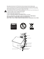
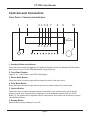
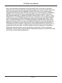
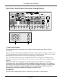
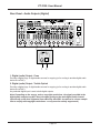
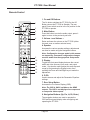
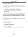
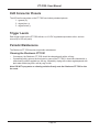
Important Safety Precautions and Explanation of Symbols
!
!
The exclamation point within an equilateral triangle is intended to alert the user to the presence of
important installation, operation, and service instructions in this manual.
The lightning flash with arrowhead symbol within an equilateral triangle is intended to alert the user
to the presence of uninsulated dangerous voltages within the enclosure that may be of sufficient
magnitude to constitute a risk of electrical shock to the user.
Please read this manual thoroughly before attempting to install, configure, or operate the Sherbourn
PT-7030. After successful installation and configuration of the PT-7030, be sure to retain this manual in
a safe place for future reference.
Safety is a key component to a long lasting and trouble free installation. Please read and follow
all instructions and heed all warnings on the PT-7030 and in this manual. The vast majority of the
subsequent safety precautions are common sense. If you are not comfortable with the installation
of audio/video entertainment equipment, you should seek the services of a qualified installation
professional or call us for help.
WARNING: TO REDUCE THE RISK OF FIRE OR ELECTRIC SHOCK, DO NOT USE THE
PT-7030 NEAR WATER OR IN WET LOCATIONS, DO NOT EXPOSE IT TO RAIN OR MOISTURE,
DO NOT EXPOSE IT TO DRIPPING OR SPLASHING FROM OTHER SOURCES, AND ENSURE
THAT NO OBJECTS FILLED WITH LIQUIDS (SUCH AS VASES) ARE PLACED ON IT. DOING SO
MAY RESULT IN DAMAGE TO THE PT-7030 AND THE RISK OF ELECTRIC SHOCK, WHICH MAY
RESULT IN BODILY INJURY OR DEATH.
WARNING: TO REDUCE THE RISK OF ELECTRIC SHOCK, DO NOT REMOVE THE COVER
FROM THE PT-7030. THERE ARE NO USER-SERVICEABLE PARTS INSIDE THE PT-7030. REFER
ALL SERVICE TO QUALIFIED SERVICE PERSONNEL.
Do not install the PT-7030 near or above any heat sources such as radiators, heating vents, or other
apparatus’ that produce heat. Do not block any ventilation openings or heat sinks. Avoid installing
the PT-7030 directly above other heat-producing equipment unless sufficient ventilation or forced-air
cooling is provided.
Do not install the PT-7030 in locations without proper ventilation. The PT-7030 should not be operated
on a bed, sofa, rug, or similar surface that may block vents. The PT-7030 should not be installed in an
enclosed location such as a bookcase, cabinet, or closed equipment rack unless sufficient forced-air
ventilation is provided.
Always install your PT-7030 according to the manufacturer’s instructions and only use attachments or
accessories specified by the manufacturer.
Do not install the PT-7030 on any stand, shelf, or other piece of furniture that is unable to support its
weight. If a cart is used to move the PT-7030, use caution to avoid injury from tip-over.
Connect the PT-7030 only to power sources of the correct voltage (as shown in this manual and on
the PT-7030). Ensure that the Input Voltage selector switch on the rear of the PT-7030 is set to the
appropriate voltage.
Protect power supply cables from being pinched, walked on, or otherwise damaged. Be especially
careful where the power cable enters the power outlet and the PT-7030 unit.
Only connect the PT-7030 to an electrical outlet or extension cord of appropriate type and rating.
DO NOT defeat the safety purpose of a grounding or polarized plug by removing ground pins or using
unsafe adapters. A polarized plug has two blades - one wider than the other. A grounding plug has a
third ground prong in addition to the two main conductors. The wide blade or third grounding prong is
provided for your safety. If the provided plug does not fit your outlet, consult an electrician to replace
your obsolete outlet. If you replace the PT-7030 power cord, only use one of similar type and equal or
greater current rating.
The power cable for the PT-7030 should be unplugged from the outlet during severe electrical storms,
or when unused for a long period of time.
!
Only replace the fuse(s) in the PT-7030 with a fuse(s) of proper value and voltage rating.
The PT-7030 should only be cleaned as directed in the Installation and Operation Manual. Avoid
spraying liquids directly onto the PT-7030 and NEVER spray liquids into the vents. Care should be
taken so that small objects do not fall into the inside of the PT-7030.
You should seek service for your PT-7030 by qualified service personnel if any of the following occur:
1. The power-supply cord or the plug has been damaged.
2. Objects or liquid have fallen or spilled into the vents.
3. The PT-7030 has been exposed to rain.
4. The PT-7030 exhibits a marked change in performance.
5. The PT-7030 has been dropped, or its enclosure or chassis is damaged.
NOTE: TO COMPLETELY DISCONNECT THE PT-7030 FROM THE AC POWER MAINS,
DISCONNECT THE AC POWER CORD FROM THE AC RECEPTACLE.
NOTE: THE PT-7030 AC POWER CORD MUST REMAIN READILY ACCESSIBLE AT ALL TIMES.
CAUTION
CAUTION: TO REDUCE THE RISK
OF ELECTRICAL SHOCK, DO
NOT REMOVE COVER. NO USER
SERVICEABLE PARTS INSIDE.
REFER SERVICING TO QUALIFIED
SERVICE PERSONNEL.
Ground clamp
Antenna lead-in wire
Antenna discharge unit
(NEC section 810-20)
Electric service
equipment
Grounding conductors
(NEC section 810-20)
Ground clamps
NEC - National Electrical Code
Power service grounding
electrode system
(NEC art 250, part H)
FCC Interference Statement
Note: This equipment has been tested and found to comply with the limits for a Class B digital
device, pursuant to Part 15 of the FCC rules. These limits are designed to provide reasonable
protection against harmful interference in a residential installation. This equipment generates,
uses and can radiate radio frequency energy and, if not installed and used in accordance with
the instructions, may cause harmful interference to radio communications. However, there is no
guarantee that the interference will not occur in a particular installation. If this equipment does
cause harmful interference to radio or television reception, which can be determined by turning the
equipment off and on, the user is encouraged to try to correct the interference by one or more of the
following measures:
Reorient or relocate the receiving antenna.
Increase the separation between the equipment and receiver.
Connect the equipment into an outlet on a circuit different from that of the receiver.
Consult the dealer or an experienced radio/TV technician for help.
For questions regarding service, please contact:
Sherbourn Technologies, Inc.
131 SE Parkway Court
Franklin, Tennessee
37064
Tel 1-877-366-8324
www.sherbourn.com
PT-7030: User Manual
PT-7030
7.1 Channel AV Preamp / Processor
Contents
Important Safety Precautions and Explanation of Symbols
The Sherbourn PT-7030..............................................................................2
About This Manual.......................................................................................2
Mechanical and Environmental...................................................................3
Features......................................................................................................4
Controls and Connectors.............................................................................5
Video Mode Support and Upsampling Options.........................................25
Configuration and Operation.....................................................................26
Input Configuration Paradigm....................................................................26
Menus........................................................................................................27
Example Input Configuration.....................................................................41
Infrared (IR) and Serial (RS-232) Remote Control Codes.........................43
XLR Connector Pinouts.............................................................................44
Trigger Levels............................................................................................44
Periodic Maintenance................................................................................44
Sherbourn Technologies, LLC Ten-Year Limited Warranty........................45
Notes.........................................................................................................47
Page 1
PT-7030: User Manual
The Sherbourn PT-7030
Thank you for choosing the Sherbourn PT-7030 7.1 Channel AV Preamp / Processor. The PT-7030
is a full featured A/V pre / pro that combines outstanding video performance and audio sound quality
with support for both current and legacy video sources and all the latest surround audio formats.
When paired with a high quality power amplifier and speakers, the PT-7030 becomes the control
center of a cutting edge home theater installation, able to play all the latest video formats, support
both your new and legacy sources, and provide true audiophile quality sound.
The PT-7030 is exceptionally flexible and configurable, supports a main zone (plus up to three
additional zones), is easily integrated with popular remote control solutions, and works with a wide
variety of current and legacy equipment. Because the PT-7030 was designed from the ground up
with the custom installer market in mind, it not only provides the features in demand by most end
users, but also a variety of customization options geared towards the professional installer.
About This Manual
This manual will provide you with all the information you need to install and configure the PT-7030 to
achieve its optimum potential. The manual also includes a brief summary of the features offered by
the PT-7030 and descriptions of how the controls work.
You may wish to record serial numbers or other purchase information on the Notes page at the back
of this manual.
Page 2
PT-7030: User Manual
Mechanical and Environmental
Dimensions: 17” wide x 7.5” high x 15” deep (includes feet, connectors, no rack kit)
Weight: 33 lbs / 15 kg (unboxed); 37 lbs / 17 kg (boxed)
Rack mountable: Yes, single or paired, with optional rack mount kits
Power requirements:
115 VAC or 230 VAC +/- 10% @ 50 / 60 Hz (selectable by rear-panel switch)
Ventilation and cooling:
To avoid overheating, be sure to provide adequate clearance and ventilation. You should provide a
minimum of 4 inches clearance on all sides of the PT-7030 (including the back). If the PT-7030 is
to be installed in an enclosed space, be sure to provide adequate ventilation or forced air cooling.
Page 3
PT-7030: User Manual
Features
The Sherbourn PT-7030 is a reference-caliber home theater preamp / processor with highperformance audio and video processing, extensive integration capabilities, and support for a
wide variety of legacy video input formats. Support for all HD audio formats and true 192kHz
performance meshes seamlessly with a Genesis® Torino high performance video scaling engine
and full HDMI v1.4a switching and signal management for a theater experience beyond compare.
Some of the more important features of the PT-7030 include:
•
•
•
•
•
Six HDMI 1.4a inputs and two HDMI 1.4a outputs (one output is ARC enabled).
Twin Cirrus® 32-bit dual-core DSP processors for true 192 kHz audio performance.
Genesis® Torino high-performance video engine for true 10-bit video processing.
DCDi Cinema®Format Conversion and Truelife™ video enhancer.
Individual DACs and volume control circuits for each channel, and a very tightly regulated
multistage linear power supply ensure the absolute best audio performance.
• HDMI 1.4a Deep Color Compliant.
• Configurable CEC participation (CEC can be limited to avoid conflicts).
• Discrete multichannel parametric EQ for precise room correction.
• Full set of 7.1 balanced outputs and full set of 7.1 unbalanced outputs.
• Plenty of inputs for all your digital audio source components:
(4 x digital Toslink, 3 x digital Coax).
• Plenty of inputs for all your analog audio source components:
(one stereo pair of balanced inputs, seven stereo pairs of unbalanced inputs,
one 7.1 channel set of unbalanced direct inputs).
• Three zones of stereo audio and composite video outputs (besides the main zone).
• Component video inputs and outputs.
• Full integration with popular remote control formats.
• Bluetooth wireless audio.
• 10 year Sherbourn Technologies Limited Warranty.
You can find more information about the PT-7030 Home Theater Preamp / Processor on our website
at www.sherbourn.com.
Page 4
PT-7030: User Manual
Controls and Connectors
Front Panel - Controls and Indicators
1
2
3 4 5 6 7
2CH
STANDBY
INPUT 1
INPUT 2
INPUT 3
PLIIX
INPUT 4
OPTIONS
INPUT 5
DISPLAY
INPUT 6
8
9
MULTI-CH
MUTE
10
ZONES
INPUT 7
INPUT 8
USB
VOLUME
1. Standby Button and Indicator
Press this button to switch (toggle) the unit between Standby and On; the Standby LED illuminates
blue when the unit is On (the LED flashes blue during power-up).
2. Front Panel Display
Large (6” x 1”), clear, easy to read VFD status display.
3. Stereo Mode Button
Press this button to cycle through valid two-channel modes for the active input.
4. PLIIx Mode Button
Press this button to cycle through valid surround-sound matrix modes for the active input.
5. Options Button
Press this button to cycle the display between information for the various zones, and to change
settings in each zone. As each zone is displayed, it can be enabled or disabled with the Zones
Button (7), the Volume can be adjusted with the Volume knob, and its input can be chosen using the
Input Selector Buttons.
6. Display Button
Switches the front panel display On and Off.
Page 5
PT-7030: User Manual
7. Zones Button
Used in conjunction with the Options Button (5) to configure Zone 2, Zone 3, and Zone 4.
8. Input Selector Buttons
Press each Input Selector button to select the associated input.
Note: Each Input Selector Button is associated with a specific input configuration (the name
under the button). In addition, the PT-7030 allows you to assign a descriptive name like
“DVD” or “Cable” to each input configuration, and displays those names on the front panel
status display and the OSD when the input is chosen. Changing the descriptive name of an
input configuration will not affect which button it is associated with.
9. Mute Button
Press this button to mute the audio output; press it again to return to the previously set level.
10. Volume Control
Rotate this knob to change the level. The Volume knob on the PT-7030 is a rotary encoder which
instructs the control system to raise or lower the volume using the PT-7030’s precision digitally
controlled analog attenuator.
Party Mode
In Party Mode, the same input is routed to all zones and the recording outputs. This option can be
selected from the front panel by pressing and holding the Zone Button for three seconds. (The front
panel display will show a “P” when Party Mode is engaged.)
To cancel Party Mode, press and hold the Sel button on the remote control or the Options button on
the front panel for three seconds.
Page 6
PT-7030: User Manual
Rear Panel - Input and Output Connections
®
Page 7
PT-7030: User Manual
Rear Panel - Control Connections
®
1
2
3
4
5
6
1. Computer Input (RJ-45 connector)
Connect a computer or other RS-232 serial device to this input to perform firmware updates to
control the PT-7030 remotely via RS-232.
Note: This is an RS-232 type serial connection using an RJ-45 connector. This input MUST
be connected to an RS-232 serial port on a computer or remote control device using an
appropriate (provided) RS-232 to RJ-45 adapter cable. Refer to page 43 for serial cable
pinouts and control codes.
WARNING: DO NOT CONNECT A COMPUTER NETWORK CABLE TO THIS CONNECTOR!
Doing so will result in hardware damage to your computer equipment or the PT-7030.
2. Trigger Outputs (6)
Connect each Trigger Output to one piece of trigger-enabled audio equipment. You can then
configure the PT-7030 to turn on specific trigger-enabled equipment when a certain input is
selected.
Page 8
PT-7030: User Manual
3. Remote IR Outputs (4)
These outputs are currently inactive. When enabled, they will allow you to connect IR blasters which
the PT-7030 will use to control other components using their IR remote control codes. IR codes
for various components will be programmed into the PT-7030 using a computer connected to the
Mini-USB Socket (see below). This feature is not currently available. Please ask your Sherbourn
representative for details.
4. IR Outputs (2)
Connect one or two IR blasters to these outputs to allow IR control signals received at the Remote
Inputs or the front panel IR sensor to be relayed to components in the main room.
5. Remote Inputs (4)
Connect each of these inputs to the output of a remote IR receiver (if desired). IR receivers may be
placed in other zones to allow remote control codes to be relayed to the PT-7030. If the PT-7030
is located inside a cabinet or behind a curtain where IR signals cannot reach it, a receiver may be
placed in the main zone to relay remote control signals in the main zone to the PT-7030. If one
or two IR blasters are connected to the IR Outputs, signals received by these inputs will also be
broadcast from those outputs. (This will allow IR remote control commands from the other zones to
control equipment in the main zone - or wherever the blasters are located.)
6. Mini-USB Socket
This socket is for factory use only.
Page 9
PT-7030: User Manual
Rear Panel - Power Connections
®
1
2
3
1. Power Switch
Switches the AC main power to the PT-7030 On and Off. When this switch is Off, the PT-7030 will
not respond to trigger signals or manual controls.
2. Input Voltage Selector Switch
Always ensure that this switch is set for the proper line voltage for your area and installation.
3. Standard IEC Power Inlet
The PT-7030 can be used with either a two-wire or three-wire standard IEC power cable.
Page 10
PT-7030: User Manual
Rear Panel - Video Inputs and Outputs (HDMI)
®
1
2
1. HDMI Inputs (6)
Provide six inputs for components that have either HDMI or DVI-D outputs. (An appropriate adapter
will be required to connect DVI-D devices, and not all features will be available.) All six HDMI
inputs are identical, are HDMI 1.4 compatible, and support all standard formats (including 3D) up to
1080p/24.
2. HDMI Outputs (2)
Both HDMI outputs provide the same signal in parallel at the same time. Both outputs are HDMI 1.4;
HDMI Output 1 is ARC and CEC enabled. HDMI video signals are passed through without scaling.
3D video is only available through the HDMI outputs.
Page 11
PT-7030: User Manual
Note: The output resolution is specified in the Video Setup Menu. Analog video inputs at any
resolution will be converted to the selected resolution for output (except 3D or 1080p/24).
HDMI inputs are ALWAYS passed through to the output at the resolution in which they are
received.
Note: HDMI video signals are subject to HDCP copy protection. Video may not be displayed
properly (or you may get a blank screen) unless all connected HDMI components, including
the display or TV, are compatible with the HDCP copy protection standard. (Third party
adapters which convert HDMI output to high-definition component video may not work
properly, depending on the copy protection status of the source material. Consult the
manufacturer of your adapter for details.)
Note: The HDTV Component Video outputs on the PT-7030 are subject to HDCP copy
protection. Component Video Outputs may not display 720p, 1080i, or 1080p video when
the source signal is copy protected. All sources will, however, be available when the
output resolution is set to 480p/576p. (Pending changes to the copy protection standard
requirements may result in no output at all from the component outputs with certain copyprotected HDMI source content.)
Note: Most TV monitors with DVI-D connections can be successfully connected to the HDMI
Outputs on the PT-7030. There may, however, be compatibility issues with some older DVI-D
equipped monitors. DVI-D monitors must support the HDCP copy protection protocol to work
properly with copy protected content.
Note: By default, only audio received from the source component is sent to the TV via the
HDMI Outputs. To send decoded audio from the PT-7030 to the TV, select TV Mode in the
Video menu.
Page 12
PT-7030: User Manual
Rear Panel - Video Inputs and Outputs (Component and Composite)
®
1
2 3
4
1. Zone Video Outputs (Zone 2 - Zone 4)
Provide video outputs for Zones 2, 3, and 4 (composite only). Video inputs are assigned to the
zones in the Zone Setup Menu.
2. Composite Video Inputs (1 - 2) and Composite Video Output
Composite Video Inputs 1 and 2 accept composite video from a source component; the input is
upsampled, and is available at the HDMI Outputs. Signals from the selected Composite Video Input
are routed to the Composite Video Output for the main zone (for use with a composite monitor), and
to the Zone Video Outputs.
Note: The Composite Video Output and Zone Video Outputs will ONLY provide video signals
when there is a composite signal available from one of the Composite Video Inputs.
Note: The OSD is only displayed over video on the HDMI output; it is not displayed on video
output from the Composite Video outputs.
Page 13
PT-7030: User Manual
3. Component Video Outputs (1 set)
Provide a component video version of the main zone video output.
Note: The Component Video Output will ONLY provide video signals when there is a
component video signal available from one of the Component Video Inputs.
Note: The OSD is only displayed over video on the HDMI output; it is not displayed on video
output from the Component Video outputs.
4. Component Video Inputs (2 sets)
Provide inputs for component video sources (2); the input will be upsampled at high quality to the
output resolution specified (if different from the input resolution) and can be output on HDMI.
Note: If the PT-7030 is connected to a TV which cannot show the selected output resolution
(you get a blank screen), pressing the 2CH and Mute buttons on the front panel at the same
time will change the video resolution to 480p/576p.
Page 14
PT-7030: User Manual
Rear Panel - Audio Inputs (Analog)
®
1
2
3
4
1. Reference Stereo Input
Provides a balanced analog input for connecting a reference quality stereo component
to the PT-7030 (typically the balanced analog output of a CD player or high-end BD player). This
input is always assigned to Input 1 when used.
2. Tuner Input
Provides an unbalanced stereo audio input. (This input is assigned to Input 2 when used, but can be
used for any unbalanced analog stereo audio source.)
3. Unbalanced (audio) Inputs (1 - 6)
Provide six sets of unbalanced stereo audio inputs, which are assigned to Input 3 through Input 8.
These inputs can be used for the audio channels from composite or component video sources, or
for inputs from audio-only components.
Page 15
PT-7030: User Manual
4. 7.1 Unbalanced (audio) Inputs (1 set)
Provides one set of unbalanced 7.1 channel surround audio inputs. Normally, the signals received
at these inputs bypass all digital processing and are passed directly to the volume control and
the preamp outputs. Typically, the analog surround sound outputs of an SACD player or external
decoder are connected to these inputs.
An optional bass management feature sums the 7 main channel inputs (while still passing them
unaltered to the outputs), and connects the summed input signal through a 100 Hz low-pass filter to
the subwoofer output. This is useful if the 7 main input channels don’t include a subwoofer or LFE
(low frequency effects) channel.
HDMI Audio (output)
By default, audio is passed directly from source components to the TV via HDMI, and decoded
audio is delivered at the PT-7030’s audio outputs. You may also choose to have audio decoded by
the PT-7030, and then have the decoded audio sent to the TV via the HDMI connection, by selecting
TV Mode in the Video Menu.
Note: When TV Mode is enabled, the PT-7030 itself will no longer source audio from its other
audio outputs.
Page 16
PT-7030: User Manual
Rear Panel - Audio Inputs (Digital)
®
1
2
3
1. USB Audio Input
Provides a connection for various USB audio devices.
If a USB memory stick (or other memory device) is connected, the PT-7030 will automatically detect
music files of supported types on it.
If the included USB Bluetooth adapter is inserted, you will be able to stream music from a
compatible Bluetooth audio device (like a mobile phone). When the Bluetooth adapter is inserted,
the PT-7030 will display a “Ready” status; when your device is activated it will display “Bluetooth”.
When asked for a password, enter “0000” and accept. The PT-7030 will show on the OSD that a
device is attempting to connect. Press Enter on the PT-7030 remote control and the PT-7030 will
display “Running” on the OSD. At this point you will be able to stream audio to the PT-7030 from
your Bluetooth device.
Page 17
PT-7030: User Manual
2. Digital Inputs - Toslink (1 - 4)
Provides input for digital audio sources in standard Toslink optical S/PDIF format. Digital audio from
CD players or other stereo devices and standard surround formats such as Dolby Digital and DTS
are supported.
3. Digital Inputs - Coax (1 - 3)
Provide inputs for digital audio sources in standard electrical S/PDIF format. Digital audio from CD
players or other stereo devices and standard surround formats such as Dolby Digital and DTS are
supported.
HDMI Audio (output)
By default, audio is passed directly from source components to the TV via HDMI, and decoded
audio is delivered at the PT-7030’s audio outputs. You may also choose to have audio decoded by
the PT-7030, and then have the decoded audio sent to the TV via the HDMI connection, by selecting
TV Mode in the Video Menu.
Note: When TV Mode is enabled, the PT-7030 itself will no longer source audio from its other
audio outputs.
Page 18
PT-7030: User Manual
Rear Panel - Audio Outputs (Main Analog Outputs)
®
1
2
Main Outputs
1. 7.1 Unbalanced (audio) Outputs
Provide one set of unbalanced audio outputs for connection to your main zone power amplifier(s)
and up to two powered subwoofers.
2. 7.1 Balanced (audio) Outputs
Provide one set of fully balanced audio outputs for connection to your main zone power amplifier(s)
and up to two powered subwoofers.
Page 19
PT-7030: User Manual
Note: Typically all bass management is done by the PT-7030. If your main or surround
speakers are not full range, then they should be configured as “small” in the PT-7030 setup
menu, and appropriate crossover points should be set for them. Since advanced bass
management is performed by the PT-7030, any crossovers or other frequency modification
options on your main and surround channel amplifiers, and any crossover controls on
your powered subwoofer or subwoofer amplifier, should be set to “flat” or “direct”. If your
subwoofer has a non-defeatable internal crossover, it should be set to the highest allowed
crossover frequency to minimize interference with the bass management in the PT-7030.
Note: 7.1 Balanced Outputs and 7.1 Unbalanced Outputs provide the same output signal,
and both are always active. You may use unbalanced connections for some channels and
balanced connections for others if desired. (To ensure the best possible audio fidelity, it
is desirable to make connections symmetrical: connect both speakers of a given type - for
example, both side surrounds - to similar amplifiers using the same type of connection.)
Note: Both subwoofer outputs are the same (they are not stereo). If you are using two
subwoofers, and you wish to vary the relative output between them, you should do so using
the controls on the individual subwoofers.
Page 20
PT-7030: User Manual
Rear Panel - Audio Outputs (Secondary Analog Outputs)
®
1
2
1. Zone (audio) Outputs
Provide separate stereo unbalanced audio outputs for each secondary zone (Zone 2, Zone 3,
and Zone 4).
Each zone audio output may be configured to deliver the same signal as is playing in the main zone
(by selecting Source in the Zone Setup Menu for that zone). When audio for a zone is set to Source,
analog sources will be routed to the zone if they are playing in the main zone.
Each zone audio output may also be configured to deliver audio content from a different source
than the source selected for the main zone. If so, however, you may ONLY choose ANALOG audio
sources.
Note: If you wish to be able to select a specific signal source to listen to in one of the
secondary zones, then you MUST connect an analog version of that source. For example, if
you have your CD player connected to your PT-7030 via a digital connection, but you wish to
also be able to listen to CDs independently in Zone 2, then you must ALSO connect the
analog audio connection between the CD player and the PT-7030.
2. Audio Out
Provides a stereo analog audio output for connecting to the input of a video recorder.
Page 21
PT-7030: User Manual
Rear Panel - Audio Outputs (Digital)
®
1
2
1. Digital (audio) Output - Coax
Provides a digital copy of digital audio sources for copying (or for routing to another digital audio
device like a DAC).
2. Digital (audio) Output - Toslink Optical
Provides a digital copy of digital audio sources for copying (or for routing to another digital audio
device like a DAC).
Any selected digital input is sent to both digital outputs.
Note: Depending on the source, and on copyright restrictions, the signal provided at the
digital audio outputs may NOT be at the same quality as the main digital audio channel.
(Specifically, audio that originated from a Blu-Ray disc WILL be reduced to a lower sample
rate to comply with copyright restrictions - or may even be entirely suppressed.)
Page 22
PT-7030: User Manual
Remote Control
1. On and Off Buttons
1
2
The On button switches the PT-7030 On; the Off
Button returns the PT-7030 to Standby. The rear
panel Power switch must be in the On position for the
PT-7030 to operate.
4
3
5
6
7
Press this button to mute the audio output; press it
again to return to the previously set level.
8
3. Volume + and Volume --
2. Mute Button
Raise and lower the volume on the PT-7030 (either
the main zone or another selected zone).
4. Speaker
Accesses the various speaker settings; adjustments
can then be made using the Navigation buttons.
9
10
11
2CH
PLCM
SUR+
SEL
USB
IN1
IN2
BAND
IN3
IN4
IN5
PTY
IN6
IN7
IN8
MULTI
12
13
14
15
Note: Configuration changes made in this manner
are temporary. Permanent configuration changes
must be made from the appropriate Setup menu.
5. Display
Toggles the front panel display between the current
audio and video sources, input mode, and output
mode. Can also be used to adjust the audio dynamic
range by first pressing the Display button, then
pressing the Down and Left/Right keys to make the
adjustment.
6. P-EQ
PTR 100
Used to access and adjust the Parametric Equalizer
settings.
7. Rcvr Setup Button
Accesses the On-Screen Display (OSD).
Note: The OSD is ONLY availabe on the HDMI
outputs. The OSD is not displayed on component
or composite video outputs.
8. Navigation Buttons (Up, Dn, Lt, Rt, Enter)
The navigation buttons are used to operate the
OSD and front panel display when configuring and
operating the PT-7030.
Page 23
PT-7030: User Manual
9. Random Button
When playing music from a USB stick, this button causes songs to be played in random order
(“shuffle mode”).
10. Playback Buttons
These buttons provide basic playback controls for audio played from a USB stick.
11. Mode Control Buttons
The 2-CH Button changes the audio mode to Stereo, Down-Mix, or Bypass.
The PLCM Button toggles the audio mode to Pro Logic Cinema or Music.
The SUR+ button allows you to view or change the current surround mode and configure the
automatic dynamic range control. Press the Sur+ button to view the information; while the
information is displayed, the Lt and Rt navigation buttons switch between surround modes and the
Dn navigation button switches between dynamic range options.
12. Sel Button
Allows you to configure options for each zone. Press the Sel button repeatedly until the desired
zone appears in the display. Once the desired zone is selected, you have 10 seconds to make
changes. (Press an Input Selector button to choose a different input, or use the Volume + and
Volume -- Buttons to change volume for the zone.)
13. Input Selector Button
Each button directly selects an Input.
Note: You must configure the specific video and/or audio source for each input.
14. [UNUSED]
15. Multi (Input Selector Button)
Selects the 7.1 channel (“Multi-Channel”) unbalanced audio input.
Note: The remote control for the PT-7030 can be configured to use an alternate set of IR
control commands (to avoid conflicts with the codes used by some other device). The
default command set is Set 1, and the alternate command set for the main zone is Set 2. To
configure the remote control to use IR Command Set 2, press the In2 and Number 2 buttons
on the remote AT THE SAME TIME. Then point the remote control at the PT-7030 and hold the
Number 2 button for at least five seconds (a message will display on the front panel “AUD ID:
-->2” to acknowledge the change). To reset the PT-7030 and remote to use Set 1, repeat the
procedure using IN2 and the Number 1 button.
Note: The remote control for the PT-7030 can be configured to directly control Zone 2, Zone
3, or Zone 4. (This feature could be used to enable you to put IR repeater receivers in your
other zones and configure a remote control to work specifically in each zone, or simply to
temporarily control another zone more easily from your main remote.) To configure the
PT-7030 remote control to control a specific zone, press the In2 button and the Number
button that corresponds to the zone on the remote control at the same time.
Zone 2 = press In2 and “3”
Zone 3 = press In2 and “4”
Zone 4 = press In2 and “5”
Press In2 and 1 (or 2 if you are using Command Set 2) to return the remote to normal.
Page 24
PT-7030: User Manual
Video Mode Support and Upsampling Options
HDMI Inputs
Signals received at the HDMI inputs of the PT-7030 are passed directly to the HDMI outputs without
resampling to ensure the best possible output quality. Video signals received at the HDMI inputs are
not available at the composite or component outputs.
Note: The output resolution is specified in the Video/HDMI Setup menu. This setting ONLY
applies to analog video inputs; HDMI inputs are ALWAYS passed through to the output at the
resolution in which they are received.
Composite and Component Inputs
Signals received at the composite inputs are passed directly to the composite outputs at the same
resolution in which they are received.
Signals received at the component inputs are passed directly to the component outputs at the same
resolution in which they are received.
Signals received at the composite and component inputs are upscaled at high quality to the output
resolution selected in the Video/HDMI menu and are available at the HDMI outputs at resolutions
(up to 1080p).
Note: The output resolution is specified in the Video/HDMI Setup menu. Analog video inputs
at any resolution will be converted to the selected resolution for output (except 3D or
1080p/24).
Page 25
PT-7030: User Manual
Configuration and Operation
Note: The On-Screen Display (OSD) is ONLY displayed on the HDMI outputs.
Input Configuration Paradigm
The PT-7030 allows any input connector to be assigned to any input source using the Input Setup
configuration screen.
By default, the source input buttons are configured as follows:
InputInput Connector
Input 1
Reference Stereo (balanced)
Input 2
Tuner
Input 3
Analog 1
Input 4
Analog 2
Input 5
Analog 3
Input 6
Analog 4
Input 7
Analog 5
Input 8
Analog 6
Note: When using HDMI video sources, it is a good idea to also connect the matching
composite video input connections from each source. This will allow you to use those
source components with Zone 2, Zone 3, and Zone 4 (only composite video is routed to the
additional zones).
Note: When using digital audio input connections, it is a good idea to also connect the
matching analog input connections from each source component. This will allow you to use
those source components with Zone 2, Zone 3, and Zone 4 (only analog audio is routed to
the additional zones).
Note: Operation of the PT-7030 is relatively straightforward, and some screen hints are
provided to make navigation easier.
On certain Menus (like Input Setup and EQ), each screen contains a “page” of related
information. (Each Menu screen under Input Setup shows the information for one input, with
the top line showing the name of the input. The Left/Right buttons navigate to the screen for
the previous/next input.)
On some menus, Yes / No choices lead to additional screens with additional options.
(On the Preferences screen, setting Default:NO and pressing Enter does nothing, but setting
Default:YES and pressing Enter opens a screen containing several options related to saving
and retrieving default settings.)
Page 26
PT-7030: User Manual
Menus
Main Menu
MAIN MENU
INPUT SETUP
SPEAKER SIZE
VIDEO SETUP
LEVEL CAL.
ZONE SETUP
SPKR DISTANCE
PREFERENCES
CROSSOVERS
SYSTEM STATUS
SUB LEVELS
EQUALIZER
EXIT
The Main Menu is used to access all configuration options on the PT-7030.
Page 27
PT-7030: User Manual
Input Setup
INPUT SETUP
INPUT NAME:
INPUT LEVEL:
INPUT TITLE:
AUDIO SOURCE:
VIDEO SOURCE:
DEFAULT MODE:
TRIGGERS ACTIVE:
LIP SYNC:
CINEMA EQ:
INPUT 1
0dB
BLURAY
HDMI
HDMI 1
Dolby PLII Mus
1 2 3 4 5 6
0mS
OFF
RETURN
EXIT
The Input Setup Menu is used to configure each input. For each input you can configure an Input
Name, an Input Level (level trim), an Input Title, an Audio Source, a Video Source, a Default Mode
for use when that input is selected, a list of which Triggers will be active when that input is selected,
a Lip Synch delay for use when that input is selected, and whether Cinema EQ is active when that
input is selected.
Note: When an HDMI video source is selected, choosing HDMI as your audio source will
automatically select the audio from the selected HDMI video source.
Note: When Lip Synch is set to 0mS, the lip synch delay will be automatically configured
based on HDMI parameters. Setting any other value overrides this choice and configures the
selected value manually as your chosen delay.
Page 28
PT-7030: User Manual
Video Setup
VIDEO SETUP
ANALOG VIDEO
RESOLUTION: 1080p
HDMI AUDIO: TO AMPLIFIER
CEC CONTROL: OFF
CEC POWER: OFF
RETURN
EXIT
The Video Setup Menu is used to configure the video output resolution when a component or
composite video input is selected, to configure whether or not the PT-7030 sends audio output to
your amplifier (the PT-7030 Main audio outputs), and to set CEC Control options.
Note: The Video Resolution setting in this menu only applies when an analog video source
(component or composite video) is selected. HDMI video is always passed to the output at
the same resolution in which it is received.
Note: HDMI Audio must be set to Amplifier if you want the PT-7030 to decode your audio and
send it to your power amplifier and speakers. If you set HDMI Audio to TV, audio will be sent
to your monitor or TV but NOT to your amplifiers via the PT-7030.
Note: You may independently enable CEC Control for power only, or full CEC Control for all
functions supported by your attached device. If full CEC control doesn’t work properly with
a specific device, limiting CEC control to power only may prevent undesirable interactions
while still allowing you CEC control of basic On/Off functionality.
Page 29
PT-7030: User Manual
Zone Setup
ZONE SETUP
ZONE:
AUDIO:
VIDEO:
TRIGGERS ACTIVE:
VOLUME:
MAXIMUM VOLUME:
START UP VOLUME:
ZONE3
Off
Off
- - - - - Variable
Max
70
RETURN
EXIT
The Zone Setup Menu is used to configure the audio and video signal source for each zone, which
Triggers are active when each zone is enabled, and the volume behavior for each zone. Use the left
and right arrow keys to select the individual Zone Setup Menu screen for each zone.
Each zone audio output may be configured to deliver the same signal as is playing in the main zone
(by selecting Source in the Zone Setup Menu for that zone). When audio for a zone is set to Source,
analog sources will be routed to that zone if they are playing in the main zone.
Each zone audio output may also be configured to deliver audio content from a different source
than the source selected for the main zone; if so, however, you may ONLY choose ANALOG audio
sources.
Note: If you wish to be able to select a specific signal source to listen to in one of the
secondary zones, then you MUST connect an analog version of that source. For example, if
you have your CD player connected to your PT-7030 via a digital connection, but you wish to
also be able to listen to CDs independently in Zone 2, then you must ALSO connect the
analog audio connection between the CD player and the PT-7030.
Page 30
PT-7030: User Manual
Preferences
PREFERENCES
RECORD OUT:
START UP VOLUME:
MAXIMUM VOLUME:
LANGUAGE:
SOURCE
45
Max
ENGLISH
SOFTWARE UPDATE: NO
DEFAULT: NO
RETURN
EXIT
The Preferences Menu is used to configure several basic system options on the PT-7030, including
the Record Out source, the Startup Volume and Maximum Volume for the main zone, and the
Default Language. Changing Software Update to YES and pressing Enter will open the Software
Update sub-menu, which is used to install firmware updates to the PT-7030. Changing Default to
YES and pressing Enter will open the Default Restore Options sub-menu, which is used to store and
recall user default settings, and to reset the PT-7030 to factory defaults.
Page 31
PT-7030: User Manual
Default Restore Options (sub-menu)
DEFAULT RESTORE OPTIONS
SAVE USER SETTINGS?: NO
<RESTORE>
FACTORY SETTINGS?: NO
USER SETTINGS?: NO
SET NEW PASSWORD?: NO
RETURN
EXIT
The Default Restore Options sub-menu is used to optionally save and restore user settings, and to
restore the PT-7030 to either the factory defaults or the saved set of user settings. You will also have
the option to set and change the password used to protect the saved user settings.
Note: User settings are stored with a password to prevent unauthorized modification. The
default password is “0000”; you may also change the password on this screen (you will be
required to enter the original password to change to a new one).
Page 32
PT-7030: User Manual
System Status
SYSTEM STATUS
MAIN ZONE:
ZONE 2:
ZONE 3:
ZONE 4:
RECORD OUT:
CONTROLLER V.#:
VIDEO V.#:
SCALER V.#:
AUDIO V.#:
BLURAY
Off
Off
Off
SOURCE
V1.01
V1.01
V1.01
V1.10
RETURN
EXIT
The System Status Menu screen displays some basic settings, including the current status or
selected input for each zone and the selected Record Out source. This screen also displays the
current version of the various firmware modules installed in the PT-7030.
Page 33
PT-7030: User Manual
Speaker Size
SPEAKER SETUP
FRONT:
CENTER:
SURROUND:
BACK/HEIGHT:
SURROUND BACK:
SUBWOOFER:
Large
Small
Small
BACK SURROUND
None
YES
RETURN
EXIT
The Speaker Size Menu is used to configure whether each speaker used by the PT-7030 is
considered to be “Small” or “Large”. Speakers configured as Large receive a full range audio signal,
while those configured as Small receive only frequencies above their chosen crossover frequency.
For any speaker configured as Small, frequencies below the selected crossover frequency are
routed to the shared subwoofer. (This process of diverting low frequencies from Small speakers to
the subwoofer is known as “bass management”.)
There is also an option to use the outputs normally designated as “Back Surround Speakers” to
instead provide a “height” signal. Normally, in a 7.1 surround system, there are two side surround
speakers (Surrounds) and two rear surround speakers (Back Surrounds). The Back/Height Option
allows you to re-configure the sixth and seventh channels to be “front height” channels instead of
“rear surround” channels. If you choose this option, those two channels should be connected to
an amplifier that feeds speakers located in the upper front corners of your room. If you enable this
option, you will be presented with an alternate decoding option called “Dolby PLIIz”, which decodes
the correct information to be sent to these height speakers.
Note: You may also configure the PT-7030 so that, even if your Front Speakers are
configured as Large, bass from them is ALSO directed to the subwoofer. (This is similar to
what is sometimes called “Enhanced Bass” on some pre/pros.) To select this option, set
SUBWOOFER:MAX.
Note: In a typical home-theater system, with all small “satellite” speakers and a subwoofer,
the individual speakers are usually set to Small. In a system with large Front Left and Front
Right speakers, you should set FRONT:Large, and all other speakers to Small.
Page 34
PT-7030: User Manual
Level Calibration
LEVEL CALIBRATION
LEFT FRONT:
CENTER:
RIGHT FRONT:
RIGHT SURROUND:
BACK:
LEFT SURROUND:
SUBWOOFER:
+ 6dB
+ 5 dB
+ 6 dB
+ 9 dB
----+ 9 dB
+ 5 dB
RETURN
EXIT
The Level Calibration Menu allows you to manually calibrate the levels of each of your speakers.
(Levels are calibrated to compensate for differences in the level of the sound that reaches the
listener from each speaker. These differences may be caused by differences in speaker efficiency,
differences in distance, and variations in room acoustics.)
This menu screen instructs the PT-7030 to play a calibrated test tone from each speaker
(as you step through each one in sequence). You may then use a sound level meter (or other similar
device) to measure the actual output of each speaker and adjust each using the on-screen level trim
adjustments. (Typically, the goal is to adjust each speaker so that the sound from each arrives at
the listening position at the same level.)
Page 35
PT-7030: User Manual
Speaker Distance
SPEAKER DISTANCE
LEFT FRONT:
CENTER:
RIGHT FRONT:
RIGHT SURROUND:
BACK:
LEFT SURROUND:
SUBWOOFER:
9.5ft
8.5ft
9.5ft
7.5ft
----7.5ft
15.5ft
RETURN
2.85m
2.55m
2.85m
2.25m
2.25m
4.65m
EXIT
The Speaker Distance Menu allows you to inform the PT-7030 of the distances from the listening
position to each speaker. Sound being sent to each speaker is delayed by a carefully calculated
amount to compensate for differences in the distance between each speaker and the listening
position, ensuring the best surround sound “sound image”. If possible, distances should be accurate
to within a few inches, although good results can be achieved with far less accuracy.
Note: Even though the PT-7030 will compensate for speakers being different distances from
the listener, you will still get the best overall sound image if speakers from each set (the
Front Right and Front Left, or the two surrounds) are similar distances from the listener.
Note: If you have a large listening area (like a couch), use distances measured to the central
seat or the center of the listening area.
Page 36
PT-7030: User Manual
Crossovers
CROSSOVERS
L&R FRONT:
CENTER FRONT:
L&R SURROUNDS:
SURROUND BACK
FRONT HEIGHT:
SUBWOOFER:
50 Hz
60 Hz
80 Hz
80 Hz
100 Hz
80 Hz
RETURN
EXIT
The Crossovers Menu screen allows you to adjust the crossover point for each set of speakers.
These frequencies only affect speakers set to Small in the Speaker Size Menu.
For speakers set to Small, all audio above the crossover frequency will be sent to the speaker, while
all information below the crossover frequency will be sent to the shared subwoofer.
For the subwoofer, the crossover setting controls a low-pass filter that removes high-frequency
content from the LFE channel which is sent to the subwoofer.
Note: Crossover settings only affect speakers set to Small in the Speaker Size Menu.
Note: The subwoofer delivers both audio information contained on the LFE (low frequency
effects) channel, and all audio routed to it by the bass management system (the audio
below the crossover frequency for each small speaker). The Crossover Frequency set for
the subwoofer blocks high-frequency information on the LFE channel from being sent to
the subwoofer. This should typically be set at or above 80 Hz. DO NOT set the crossover
frequency of the subwoofer lower than 80 Hz to 100 Hz, otherwise you will eliminate useful
information in the LFE channel.
Note: In a typical home-theater system, with small “satellite” speakers and a sub, a common
choice of crossover frequency is 80 Hz. We suggest you follow any recommendations
provided by the manufacturer of your speakers; if none are provided, then use 80 Hz.
Page 37
PT-7030: User Manual
Subwoofer Levels
SUBWOOFER LEVELS
Dolby Digital:
Dolby PLIIx:
DTS:
STEREO:
MULTI-CHNL LPCM:
7.1 CHNL ANALOG:
0dB
0dB
0dB
0dB
0dB
0dB
RETURN
EXIT
The Subwoofer Levels Menu allows you to adjust the level of your subwoofer individually for each
of the common surround sound (and other) formats. (You may, for example, choose different
subwoofer levels for use when playing Dolby Digital or DTS content.)
Page 38
PT-7030: User Manual
Equalizer Setup
EQUALIZER SETUP
EQ ACTIVE: YES
EQ SETTINGS: GLOBAL
ADJUST EQ: NO
RETURN
EXIT
The Equalizer Setup screen allows you to enable equalization on the PT-7030, and to configure
whether EQ settings are Global (one setting applies to all channels) or Individual (you can adjust
each channel/speaker separately).
Changing Adjust EQ to YES and pressing Enter will open Equalizer Setup Settings sub-menu.
Note: Equalizer settings may be set to Individual (separate for each speaker) or
Global (the same for all speakers).
Page 39
PT-7030: User Manual
Equalizer Setup (settings sub-menu)
EQUALIZER SETUP
GLOBAL SETTINGS
FREQ
GAIN
40
60
100
120
160
0
0
0
0
0
Q
FREQ
GAIN
Q
2
2
2
2
2
1.30k
1.75k
4.0k
10.0k
16.0k
0
0
0
0
0
2
2
2
2
2
RETURN
EXIT
The Equalizer Setup Settings sub-menu allows you to configure the ten-band parametric equalizer
in the PT-7030. You may adjust the center frequency, gain, and Q (sharpness) of each band
individually. If EQ SETTINGS:Global was chosen in the Equalizer Settings Menu, then one setting
will apply to all channels; if EQ SETTINGS:Individual was chosen in the Equalizer Settings Menu,
then you will be able to configure the EQ settings for each channel separately. (If it is set to
Individual, then use the left and right arrow keys to switch between channels.)
Note: The subwoofer EQ requires fewer bands since the subwoofer covers a more narrow
frequency range. Because the PT-7030 has full parametric equalization, each band provides
far more precise and powerful control than would be possible with even several bands of
ordinary graphic equalization.
Page 40
PT-7030: User Manual
Example Input Configuration
The following is an example of how you might choose to configure your PT-7030. In the example,
we will be configuring a typical 5.1 surround configuration, with five speakers and a sub, and a
Blu-Ray and Cable Box as sources. The Cable Box is connected to HDMI 1 input, and the Blu-Ray
player is connected to the HDMI 2 input. Both input devices, and our monitor, support HD.
Electrical Connections
•
•
•
•
The Cable Box is connected to the HDMI 1 Input (using an HDMI cable).
The Blu-Ray Player is connected to the HDMI 2 Input (using an HDMI cable).
The Monitor (TV) is connected to the HDMI 1 Output (using an HDMI cable).
Our power amplifier is connected to the 5 main channels of the Main Output using
balanced audio cables.
• Our powered subwoofer is connected to the “.1” subwoofer output of the Main Outputs,
also using a balanced audio cable.
As with many home theater systems, our speakers are intended to be used with a subwoofer,
and so the manufacturer recommends that they be crossed over at the industry standard
80 Hz crossover point. Since the PT-7030 will be doing the bass management for all of our
speakers, we have set the crossover on our powered subwoofer to “Flat”. We have initially
set the level on our subwoofer to “0 db”.
Menu Settings
Note: In this example, we will be leaving a lot of settings at their default values, and will not
be entering several menu screens at all. Obviously, this is an example, and your system may
require different settings.
Input Setup
•
•
•
•
•
•
•
•
•
•
•
use the left/right arrows to select the screen for Input 1
leave the Input Level set to 0 dB
change the Input Title to “Cable”
set Audio Source: HDMI (audio from the same HDMI connection as the Video will be used)
set Video Source: HDMI 1
leave the other selections at their default values
use the left/right arrows to select the screen for Input 2
leave the Input Level set to 0 dB
change the Input Title to “Blu-Ray”
set Audio Source: HDMI (audio from the same HDMI connection as the Video will be used)
set Video Source: HDMI 2
Page 41
PT-7030: User Manual
Speaker Size
•
•
•
•
•
set Front: SMALL
set Center: SMALL
set Surround: SMALL
set Surround Back: NONE
set Subwoofer: YES
Speaker Distance
Set the distance from each speaker to your listening position.
(It would be ideal to measure these each to within six inches or better.)
Crossovers
• set L&R Front: 80 Hz
• set Center front: 80 Hz
• set L&R Surround: 80 Hz
• set Sub: 150 Hz
Congratulations, basic configuration for your 5.1 surround sound system is now complete.
Ideally, you should now set the speaker levels using a sound level meter.
Equalization settings may be done by ear, but more accurate results will also be achieved with a test
disc and real time analyzer (RTA).
Page 42
PT-7030: User Manual
Infrared (IR) and Serial (RS-232) Remote Control Codes
IR Control Codes
The PT-7030 accepts infrared (IR) remote control codes via several sources:
• the included infrared (IR) remote control
• a programmable remote control programmed with the correct codes
• a direct input from an IR detector (eye) connected to one of the rear-panel connectors
The full list of valid hex codes (for use with a programmable IR remote control) may be downloaded
from the PT-7030 product page on the Sherbourn website.
RS-232 (serial) Control I/O Pinout
!
The PT-7030 also accepts remote control codes via a standard RS-232 serial connection.
The full list of serial remote control codes may be downloaded from the PT-7030 product page on
the Sherbourn website.
The connector on the rear of the PT-7030 is a standard RJ-45 connector.
WARNING: The RJ-45 connector on the rear panel of the PT-7030 is not an Ethernet
connection. DO NOT attach a standard computer network Ethernet cable to this input. Doing
so may cause damage to the PT-7030 or your network equipment.
A cable is provided for connecting the PT-7030 to the RS-232 serial output of a PC computer or
remote controller (or any other device which uses a standard serial connection).
NOTE: All serial connections are NOT wired the same, and there is no established standard
for RS-232 connections carried over RJ-45 connectors. Either use the original cable provided
with your PT-7030, or ensure that your cable is wired correctly. Cables provided with other
devices may not work with the PT-7030 (and may even cause damage if used).
The diagram below shows the pinout connections for the provided serial cable, and may be used as
a guide for making custom cables.
5
4
9
3
8
2
7
1
6
RJ-45
CONNECTOR
(end view)
Page 43
PT-7030: User Manual
XLR Connector Pinouts
The XLR audio connectors on the PT-7030 use industry standard pinouts:
1 = ground (G)
2 = signal plus (+)
3 = signal minus (-)
Trigger Levels
Each trigger output on the PT-7030 delivers a +12 VDC regulated output when active, and can
source up to 100 mA (each).
Periodic Maintenance
The Sherbourn PT-7030 requires no periodic maintenance.
Cleaning the Sherbourn PT-7030
•
•
If necessary, the Sherbourn PT-7030 should be cleaned gently with a soft rag.
If something sticky gets on the front panel or case of the PT-7030, it should be cleaned with a
mild cleaning solution applied to a soft rag, followed by wiping with a clean rag dampened with
plain water and drying with a soft dry rag or cloth.
Note: DO NOT spray water or cleaning solution directly onto the Sherbourn PT-7030 or into
the vents.
Page 44
PT-7030: User Manual
Sherbourn Technologies, LLC Ten-Year Limited Warranty
What does this warranty cover? Sherbourn Technologies, LLC (“Sherbourn”) warrants its products against defects in materials and workmanship. This warranty is subject to revision at any
time.
How long does this coverage last? This warranty commences on the date of retail purchase
by the original retail purchaser and runs for a period of ten (10) years thereafter, with the following
exceptions: (1) receivers (including the SR-8100, SR-8200, and SR-120), preamp/processors
(including the PT-7030, PT-7020C4, and PT-7020), preamplifiers (including the PRE-1), and the
CD-1 CD Player (with the exception of the slot load CD engine) are covered by this warranty for
five (5) years from the date of retail purchase by the original purchaser; and (2) electromechanical
components, including the slot load CD engine on the CD-1 CD Player, and all fans (including
the C-12 Cooling Unit), are covered by this warranty for three (3) years from the date of retail
purchase by the original retail purchaser. This warranty is transferrable, upon written notification
to Sherbourn, to any person that owns the warranted product, however, if ownership is transferred,
the Term shall be no longer than five (5) years from the date of purchase by the original purchaser.
Sherbourn warrants any replacement product or part furnished hereunder against defects in
materials and workmanship for the longer of the following: (i) the amount of time remaining under
the original warranty, or (ii) 120 days from your receipt of the repaired or replaced product. The
duration described in the previous 3 sentences is hereinafter referred to as the “Term”. TO THE
FULLEST EXTENT PERMITTED BY LAW, ALL IMPLIED WARRANTIES RELATED TO THE
ORIGINAL PRODUCT AND ANY REPLACEMENT PRODUCT OR PARTS (INCLUDING IMPLIED
WARRANTIES OF MERCHANTABILITY AND FITNESS FOR A PARTICULAR PURPOSE) ARE
EXPRESSLY LIMITED TO THE TERM OF THIS LIMITED WARRANTY. SOME STATES DO
NOT ALLOW LIMITATIONS ON HOW LONG AN IMPLIED WARRANTY LASTS, SO THE ABOVE
LIMITATION MAY NOT APPLY TO YOU. A claim under this warranty must be made by you within
the Term. A claim shall not be valid (and Sherbourn has no obligation related to the claim) if it is not
made within the Term and if it is not made in strict compliance with the requirements of the “How do
you get service?” section.
What will Sherbourn do? Sherbourn will, at its option, either: (i) repair the product, or (ii) replace
the product with a new consumer product which is identical or reasonably equivalent to the product.
Sherbourn may provide you with a refund of the actual purchase price of the product in the event
(i) Sherbourn is unable to provide replacement and repair is not commercially practicable or cannot
be timely made, or (ii) you agree to accept a refund in lieu of other remedies hereunder. When
a product or part is repaired or replaced, any replacement item becomes your property and the
replaced item becomes Sherbourn’s property. When a refund is given, the product for which the
refund is provided must be returned to Sherbourn and becomes Sherbourn’s property.
What is not covered by this warranty? This warranty does not apply: (i) to damage caused by
use with non-Sherbourn products, where the non-Sherbourn product is the cause of the damage;
(ii) to damage caused by service or maintenance performed by anyone who is not a representative
of Sherbourn; (iii) to damage caused by accident, abuse, misuse, flood, fire, earthquake or other
external causes; (iv) to a product or part that has been modified after its retail purchase, where
the modification caused or contributed to the damage; (v) to consumable parts, such as batteries;
(vi) normal wear tear; or (vii) if any Sherbourn serial number has been removed or defaced and
Sherbourn cannot otherwise confirm that you are the original retail purchaser or authorized transferee. SHERBOURN SHALL NOT BE LIABLE FOR ANY INCIDENTAL OR CONSEQUENTIAL
DAMAGES ARISING FROM OR RELATED TO ANY DEFECTS IN OR DAMAGES TO ITS
Page 45
PT-7030: User Manual
PRODUCTS. SOME STATES DO NOT ALLOW THE EXCLUSION OR LIMITATION OF
INCIDENTAL OR CONSEQUENTIAL DAMAGES, SO THE ABOVE LIMITATION OR EXCLUSION
MAY NOT APPLY.
How do you get service? In order to make a claim under the warranty, you must:
1.
Call a customer service representative (“CSR”) of Sherbourn at (1-877-EMO-TECH /
1-877-366-8324). Provide the CSR with a description of your problem and the serial number of the
product for which the warranty claim is being made.
2.
The CSR will provide you with a returned material authorization number (“RMA”).
3.
Ship the product to Sherbourn at the following address, with the RMA written in large,
bold letters on the outside of the box, and with the letters “RMA” written before the number. Parcels
arriving without an RMA number on the outside of the box will be refused.
Sherbourn Technologies, LLC
Attn: Repair Department
131 Southeast Parkway Court
Franklin, TN 37064
How does state law apply? This warranty gives you specific legal rights, and you may also
have other rights which vary from state to state. CERTAIN STATES HAVE ENACTED LAWS
WHICH PRECLUDE THE WAIVER OF CONSEQUENTIAL AND INCIDENTAL DAMAGES AND/
OR PRECLUDE THE WAIVER/LIMITATION OF IMPLIED WARRANTIES. TO THE EXTENT
YOUR STATE HAS ENACTED A LAW WHICH PROHIBITS SUCH A WAIVER/LIMITATION, ALL
SUCH WAIVERS/LIMITATIONS CONTAINED IN THIS WARRANTY ARE INAPPLICABLE TO YOU.
CERTAIN STATES HAVE ENACTED LAWS WHICH REQUIRE THE DURATION OF A WARRANTY
TO BE EXTENDED (INCLUDING BUT NOT LIMITED TO DURING PERIODS OF REPAIR). TO
THE EXTENT YOUR STATE HAS ENACTED A LAW OF THIS NATURE, THEN THE DURATION
OF THIS WARRANTY WILL BE EXTENDED AS REQUIRED BY APPLICABLE LAW.
Page 46
PT-7030: User Manual
Notes
Manufactured under license under U.S. Patent Nos: 5,956,674; 5,974,380; 6,226,616;
6,487,535; 7,212,872; 7,333,929; 7,392,195; 7,272,567 & other U.S. and worldwide
patents issued & pending. DTS-HD, the Symbol, & DTS-HD and the Symbol together
are registered trademarks & DTS-HD Master Audio is a trademark of DTS, Inc. Product
includes software. © DTS, Inc. All Rights Reserved.
This product is manufactured under license from Dolby Laboratories. “Dolby”,
“Pro Logic” and the double-D symbol are trademarks of Dolby Laboratories.
All other trademarks are the property of their respective owners.
All information contained in this manual is accurate to the best of our knowledge at the
time of publication. In keeping with our policy of ongoing product improvement, we reserve the right to
make changes to the design and features of our products without prior notice.
User Manual Revision 1.5
Page 47
July 2013