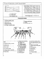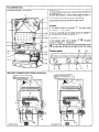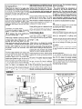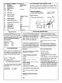
1
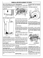
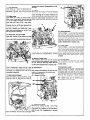
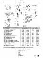
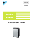
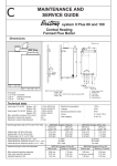
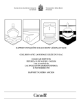
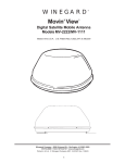
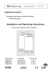
-=GvAA
MAINTENANCE AND
SERVICE GUIDE
CC
Edition et COMLEC
4/95
combi 80 and 100
Fanned Flue Combination Boiler
Heating and Instantaneous Domestic Hot Water
Dimensions
JKLMN
‘lue types:
: 12 C 22 or C42: horizontal
:32xx:
vertical concentric
Boiler outer case dimensions :
Height : 850
- Boiler width : 440 (minimum space required 450)
- Depth : 380
I
I
J
K
L
M
N
Safety valve outlet
Heating flow
D.H.W. flow
Gas supply
Cold water inlet
Heating return
Technical data
Heat input C/H & DHW Combi 80 :
Combi 100 :
Heat output C/H & DHW Combi 80 :
Combi 100 :
Max. operating pressure C/H circuit :
:
Expansion vessel net capacity
:
Expansion vessel initial pressure
Electrical consumption
:
Voltage
Electrical protection index
Fuses :
Nominal gas flow rate at 15°C and 1013
-Natural gas ( G 20) at 20 mbar
-Butane gas ( G 30 ) at 28 mbar
-Propane gas (G 31 ) at 37 mbar
Injectors and gas valves seat diameter
-Blue solenoid restrictor diameter
-Black solenoid restrictor diameter
-Manifold injectors (16)
11.73 to 28.70 kW
15.43 to 34.57 kW
9.5 to 23.25 kW
12.5 to 28 kW
2.5 bar
5.4 I
0.7 bar
15ow
230 v
IP24
2Aand 1.25A
BRITONY
mbar
Maximum
power 23.25 kW
2.74 m3/h
2.04 kg/h
2.00 kg/h
DHW flow rate at @ 30°C Combi 80 :
Combi 100 :
DHW flow rate at @ 35°C Combi 80 :
Combi 100 :
Minimum DHW operating flow rate :
:
Minimum DHW working pressure
:
Maximum DHW working pressure
Gas category
:
Combi 80
Minimum
power 9.5 kW
1.22 m3/h
0.91 kg/h
0.89 kg/h
BRITONY Combi 80
Butane or Propane
Natural qas
1.74 mm
2.40 mm
4.25 mm
5.00 mm
0.72 mm
1.23 mm
11.1 I/min
13.4 I/min
9.54 I/min
11.5 I/min
2 I/min
0.1 bar
10 bar
II 2E+ 3+
BRITONY Combi 100
Minimum
Maximum
power 12.5 kW
power 28.2 kW
3.34 m3/h
2.45 kg/h
2.42 kg/h
1.57 m3/h
1.17 kg/h
1.15 kg/h
BRITONY Combi 100
1 Butane or Propane
Natural qas
1.90 mm
2.80 mm
3.80 mm
5.20 mm
0.76 mm
1.26 mm
Pump and expanssion vessel characteristics
bar
Hauteurmanomemque
m
13
5
I,7
1
13
3
I,3
2
1
0
1,I
DPbd
100
200
300
400
5OD
600
700
800
utl
03
0,7
1 = by-pass closed
2 = by-pass open
20
50
100
150
200
250
c (I)
Note : The system initial pressure should be over the following value :
System static height (in metre) + 0.7 = Initial pressure (in bar)
10
Head available / flow
Components
1. CH Flow isolating valve
2. DHW outlet
3. Gas service tap
4. Water service tap
5. CH Return isolating valve
location
7. Pressure relief valve
8. Chassis
9. Connecting tails (x 5)
8
3
10. Steel chassis complete with expansion
Jesse1
11. Sealed chamber
12. Expansion vessel (not visible)
13. Overheat thermostat
14. Electrical box
15.Three position selector switch
16. User’s guide
17. Heating flow temperature adjustment
18. CH pressure gauge
20. Green indicator - Power ON
21. Orange indicator - Burner ON
?2. Red indicator - Lock out/flame failure
?3. Reset button
2
4
95
24. Multigas burner comprising:
-25. 16 burner head
-26. Manifold
-27. 2 Ignition electrode
-28. lonization electrode
29. Gas section comprising:
-30. Security valve (grey)
-31. l/3 gas stage (blue)
-32. 2/3 gas stage (black)
33. Right hydraulic assy
34. Left hydraulic assy
35. Single speed pump
36. Air separator
37. Heating thermistor
38. DHW thermistor
7
39. Combustion chamber made of
aluminium coated steel with 4 ceramic fibre panels to insure heat insulation
40. Copper main exchanger
41. Stainless steel secondary plate
exchanger
42. Three way valve
43. connecting bracket
44. DHW flowstat
45. Heating flowstat
46. Flue hood
47. Adjustable by-pass
49. Air Pressure switch
50. 45” elbow comprising venturi
51. Fan
WNCTIONING
the gas service tap is opened at the gasmeter and
50
pressure in central heating system is above 0.7
bar and below 2.5 bar with the pressure gauge0
(8).
3) Open the gas tap (3) by turning from right to left. 0
4) The boiler is now ready to use.
1) Turn selector switch (15) to position
on” indicator
0
flf
. The green “power
(20) will light.
2) Turn on a hot water tap, the orange “burner on” indicator
(21) will light and the water will become hot.
‘9
0
‘3 ‘3
‘3
0
x3
0
,3 ‘3
@
Heating and Hot Water
1) Turn selector
switch
“power on” indicator 0
3) If the room thermostat
(15) to position
2
‘1111.The green
will light (20).
(if fitted), the boiler temperature
control
‘1111 and the clock (if fitted) are all calling for heat, the orange
BRITONY COMBI FUNCTIONAL
DIAGRAM
12
____A
35
Hot water mode
3
“burner on” indicator 4 (21) will light and
the heating will be on.
When there is a need for hot water while
the heating is on, it is only necessary to turn
on a hot tap. The heating will be interrupted
momentarily while the hot water is being
delivered. The boiler will switch back automatically to heating when the tap is turned
water temperature is controlled by the hot
water control thermistor 38 and the central
heating control thermistor (37). This SYStern anticipates the changes of temperature in the secondary heat exchanger and
ensures accurate temperature regulation.
When the tap is closed the burner is extinguished and the pump stops. The boiler
will
now stay in the hot water mode for
Note: If the boiler has been turned off for
three
minutes to maintain temperature to
some time the first attempt to light it may
ensure a fast response in the event of a
result in a lockout @ (22) . If this happens
press the reset button (23) and the boiler subsequent hot water demand.
will light.
Priority will be given to a demand for hot
water. This will interrupt the central heaDomestic
Hot Water Mode
To be able to supply hot water, the selector ting for the duration of hot water delivery.
Off.
switch
‘11112
15 must be in either on ,:’
position. This will be confirmed
the green indicator light 0 (20)
or
by
When a tap or shower is turned on, the flow
of mains water, above 2 litres per min., will
activate the DHW flow switch (44) and
allow the 3 way valve (42) to move to the
DHW position. The pump can now circulate
primary water heated by the main heat
exchanger through the secondary
heat
exchanger.
shuts off the gas. The red lockout indicate
bulb 0 22 will light.
The central heating flow temperature i:
controlled by the central heating contra
thermistor (37). The boiler has been desi
gned to minimise cycling and will not attemp
to relight for at least 3 minutes after the boi
ler thermostat has been satisfied. When the
room thermostat is satisfied the burner wil
switch off and the pump will remain running
for a further 3 minutes before it too stops.
NB
It is possible to override the 3 minute dela!
by pressing the RESET button (23).
Lock out procedure
Flame disappearance
:
When the ionisation electrode (28) does no
Central Heating Mode
To be able to supply heating, the selector detect flame presence. The orange indicate
A lighting cyck
switch (15) must be on ‘Ill1 c? position. lamp (21) extinguishes.
starts.
If
a
flame
is
not
detected
before f
This will be confirmed by the green indicaseconds, the grey security solenoid (30) ark
tor light 0 (20).
the blue i/3 solenoid (31) will close. The
lock out red indicator (22) lights, the pump
When there is a demand for heating
(35) runs and the 3 way valve (42) stays ir
(either from the room thermostat or the
Its position.
clock) the pump starts. If the boiler tempeAfter a few seconds, it will become possibk
rature control is calling for heat and prima- to reset the boiler by pressing the reset but
ry flow rate over 4 Itr/min, the central ton (23).
heating flow switch operates ailowing the
.
Ignition sequence to begin. The first stage Overheat detection
:
solenoid (31) (blue) and security solenoid If an overheat is detected by the senso
(30) (grey) open together to allow gas to (13), the grey security solenoid (30) and the
the burner. The ignition sequence begins blue i/3 (31) closes, the orange indicate
and a continuous high speed spark ignites lamp (21) extinguishes. The ignitor is energi
the gas. As soon as a flame is detected sed for 8 seconds and the red lockout indi
cator (22) ligths. If the burner cannot religh
the orange indicator bulb b (21) will light.
the boiler will go to lockout.
After 45 seconds the second stage solenoid (32) (black) opens to allow the full
gas rate, lf a flame is not detected, after 8
The first stage solenoid (31) (blue) and
security solenoid (30) (grey) open together
to allow gas to the burner. The ignition
sequence begins and a continuous high
speed spark ignites the gas. As soon as a
flame is detected the orange indicator bulb
h (21) will light and the second stage solenoid (32) (black) opens to allow the full gas
rate. If a flame is not detected, after 8
seconds, the security solenoid closes and
shuts Off the gas. The red lockout indicator
bulb @ (22) will light. The domestic hot seconds, the security solenoid closes and
WIRING
rEiimiq
Plug for main power and Room
thermostat connection
1
El
4
2
3
4
1. Neutral
2. Phase
3. Room thermostat live
4. Accelerator resistor
5. Common for Accelerator
thermostat.
5
and room
I
ELECTRICAL WIRING continuation
Wiring
IU”
Designation
13.
14.
I4a.
14b.
I4c.
l4d.
I4e.
I4f.
149.
18.
27.
28.
30.
31.
32.
35.
37.
38.
$2.
$4.
$5.
51.
ADJUSTMENTS
colours
The following adjustments are available on the regulation PCB. To
gain access to them, pivot down electrical box, remove the rear
cover and the rear panel of electrical box, unplug connectors from
regulation PCB and pull it toward you.
Brown
-Overheat sensor
-Electrical box
-Regulation PCB
-Igniter
-Fuse 1.25 A
-Fuse 2A
-Power PCB
-Room thermostat
-Mains 230V 50 Hz
-Pressure switch
ON CONTROL
Red, Black
2: Black P: Orange
1: White
White
-Spark electrodes
White
-Ionisation probe
-Security solenoid (grey)
Grey
-2/3 gas stage solenoid (black) Black
-l/3 gas stage solenoid (blue) Blue
-Pump
-C/H thermistor
Violet
-DHW thermistor
Green
White, Yellow, Orange
-3 way valve
-DHW flow switch
Brown
-C/H flow switch
Red
-Fan
Brown. Blue
Heating output limitation :
- Functioning without limitation
- Functioning at l/3 gas rate only
plug C on “P MAX”
plug C on “P l/3”
Burner functioning:
- Regulation available 3/3, l/3, 0
- Functioning at full gas rate only
plug D on “NOR”
plug D on “TUR”
1
I
ROUTINE SERVICING
REGULATION
Temperature regulation for both C/H and
DHW circuits are controlled by 2 thermistors. The C/H knob allows the adjustment
Df temperature between 35 and 85°C. The
DHW temperature is limited to 60°C. DHW
and C/H thermistors are identical and
interchangeable.
Resistance value are
25 “C
-5000 Q at
40°C
-2631 Q at
80°C
-620 52 at
11o”c
-255 Q at
FLOW SWITCHES
Flow in both D.H.W. and Heating circuits
are detected by 2 flow switches. A piston
with a magnet at the top operates a REED
switch. The piston is lifted by flow rates
listed below :
Flow rate threshold :
120 I/h ?20 I/h
D.H.W.
C/H 250 I/h *20 I/h
AIR PRESSURE
SWITCH
The air flow rate is detected by a pressure
differential created by a venturi located in
the flue duct.
ON threshold
OFF threshold
AP > 130 Pa
AP < 100 Pa
To ensure continued efficient operation of
the appliance, it is recommended that it is
checked and serviced as necessary at
regular intervals. The frequency of servicing will depend upon the particular installation condition and usage, but in
general, once a year should be adequate.
It is the law that any service work must be
carried out by a competent person such
as your local Chaffoteaux Service Centre,
British Gas or other CORGI registered
personnel in accordance with the current
Gas Safety (Installation and Use)
Regulations.
The service schedule should
the following operations:
include
- Check the pressure in the system.
- Check the correct operation of the
appliance.
- Check the correct operation of the gas
controls.
- Check the functions of the safety
controls.
- Check combustion chamber insulation
panels for damage.
- Clean the burner.
- Clean the heat exchanger.
- Check the burner manifold injectors.
- Clean gas and water filters.
- Check expansion vessel charge pressure.
- Clean and check operation of safety
valve.
Additional
necessary:
Procedures
- Check that the fan blades are clean.
- Check, clean and replace components as
necessary.
- Carry out combustion test utilising the tes
points in the flue turret.
SUGGESTED
CING
SEQUENCE
for SERVI-
Before disconnecting or removing any
parts, isolate the gas and electricity supplies. Ensure that the appliance is cool.
(for detail please see section on Parts
Removal and Replacement)
Preliminary
Checks
- Remove outer case
- Check the system pressure is at least
0.7 bar cold
- Check operation of l/3 and 2/3 solenoids
- Check that the burner is extinguished full:
when both solenoids are closed in both
DHW and C/H modes.
- Test ionisation functions and check that
lockout occurs by turning off gas tap.
-Whilst boiler is operating, check operatior
of primary flow switch by closing heating
flow valve and by pass screw (turn clockwi
se) noting the number of turns so that it
may be reset correctly.
that may be
- Check burner pressure and gas flow
rates.
5
REMOVAL AND REPLACEMENT
efore removing appliance case, isolate
e gas and electrical supplies. Isolate boir from the system and drain before remong any component in the waterways.
nsure that the appliance is cool.
1
OF PARTS
5. Ignition Electrodes
Carry out steps 1 and 2 as above. Hinge
down electrical box by pressing retaining
tabs P on either side.
Remove wiring cover C. Disconnect leads
front panel as in steps 1 and 2. Disconnec
three pressure switch cables noting the1
positions.
1 = white cable connected to NC
2 = black cable connected to NO
Outer Case
and
C
t free. When replacing, carefully locate on
gs (B) on top edge of chassis.
from spark generator. Loosen screws securing the closure plate and remove. Remove
grommet from base of sealed chamber.
Remove screw securing electrode bracket
and lift clear easing spade connectors
through the grommet. Reassemble in reverse order, twisted together electrodes cable
at least IO times to avoid electrical interference.
6. Burner Assembly
Carry out steps 1,2, disconnect electrodes
as mentionned in section 4 and 5. Remove
two screws securing burner assembly to the
back panel of the boiler. Lift right hand back
corner first. Reassemble in reverse order.
7. Gas Solenoids
Disconnect colour coded leads. Remove six
screws. The solenoids are attached to their
base plate. Lift clear taking care not to lose
the
three
plungers
and
springs.
Reassemble in reverse order replacing the
cork gasket.
P = orange cable connected to C
Remove screw securing the switch bracks
to the chassis. Disconnect the samplin!
tubes again noting their positioning (+ an
-). Remove switch. Reassemble in revers
order.
11. Pressure Switch Venturi
Carry out steps 1, 2 and 8, as above
Disconnect the sampling tubes and rema
ve the screw securing the venturi to thl
flue outlet. Remove venturi by the botton
of the 45” elbow. Reassemble in revels
order.
12. Drain down
5 drain points are located on the boiler
Combustion
Chamber
iscrew four self tapping screws securing
s sealed chamber front panel and lift
er top corner locating lugs. Unscrew four
If tapping screws to release combustion
iamber front plate and lift clear.
?assemble in reverse order.
8. Fan Assembly
Remove outer case and sealed chamber
front panel (See Steps 1 and 2). Disconnect
spade connectors noting positions. Remove
two screws securing the front of the fan
assembly and loosen screw on flue outlet.
Twist fan assembly anticlockwise to disengage from flue outlet and lift clear.
Burner Manifold
Re-assemble in the reverse order ensuring
lrry out steps 1 and 2 as above. Remove that the wiring is re-connected correctly and
o screws securing the closure plate and the screw on the flue outlet tightened.
? remaining four screws to release the
mifold. Lift clear. Replace the manifold 9. Flue Hood
sket. Reassemble in reverse order.
Carry out steps 1 and 2 as above. Remove
fan assembly as in step 8. Remove the
Ionisation Electrodes
three screws securing the angled top of the
trry out steps 1 and 2 as above. Loosen hood to the chassis. Lift and remove taking
rews securing the closure plate and care not to snag the pressure switch cables.
nove. Disconnect the lead from the main Re-assemble in the reverse order ensuring
ring loom. Remove screw securing elec- that the hood is located behind the combusIde to burner. Thread wire through grom- tion chamber rear panel.
9 and lift clear. Reassemble in reverse
der.
10. Pressure Switch
Remove outer case and sealed chamber
(air sebarator)
1 = DHW circuit drain point
2 = Heating circuit drain point
13. Water filters ( DHW and Heating)
The DHW filter ensures a seal between the
connecting bracket and the pipe to the
DHW flow switch. Drain the boiler as ir
step 12. Unscrew the pipe nut and remove
the clip on the hydraulic assy. Pull the pipe
toward you and remove the water filter
from its location.
The C/H filter is located in the right hydrau
lit assembly. Remove the return pipe a:
described previously and withdraw the fit
ter. Reassemble in reverse order.
14. Flow switches
Drain boiler as in step 12. Disconnect the
electrical plug, turn the top cover anticlockwise,
remove the O-ring and the
brass piston. Reassemble in reverse order.
toward you to remove. Reassemble
se order.
in rever-
H
18. Pump
Drain boiler as in step 12. Pivot the electical
box downwards. Open the electrical box
cover removing the 2 screws. Remove the
15.3-Way valve
pump plug from the power board and earth
Drain boiler as in step 12. Remove the 3 plug from earth socket. Unscrew the nut (F)
clips on the 3 way valve. Remove the clip of the return pipe from the volute. Remove
on the exchanger flow pipe. Pull the pipe
down then pull it out of the 3 way valve.
Disconnect
the plug from the motor.
Unscrew the nut on the pipe between the
connecting bracket and the 3 way valve
and pull it toward you. Rotate the 3 way
valve body anti-clockwise to unclip it from
22. Spark generator
the left hydraulic assembly.
Carry out steps 1,2, and open the electrical
box cover as mentionned in step 5. Undo
16. Secondary heat exchanger
the
4 screws of the electrical rear panel and
Drain both circuits of the boiler as in step
remove it. Unplug electrodes wires, remove
12. Unscrew the 2 fixing screws (D) and
the ignitor connector from the PCB, remove
remove the DHW exchanger from the front.
earth plug from earth socket. Hang out the
ignitor. Reassemble in reverse order.
23. Power board
Carry out steps 1, 2, and open the electrical
box cover as mentionned in step 5. Undo
the 4 screws of the electrical rear panel and
the clip (G) on the pump volute and pull remove it. Unplug all cables from the PCB,
pump toward you. Reassemble in reverse remove earth plug from earth socket. Hang
out the power board. Reassemble in reverorder.
se order.
19. Pressure relief valve
The pressure relief valve can be serviced
from the front of the appliance. Drain the boiler first, undo the retaining screw and pull
out the valve.Reassemble
in reverse order.
Prior to reassembly, check that the 4 gaskets are correctly positioned. The heat
exchanger is so designed that it cannot be
remounted incorrectly.
17. Main heat exchanger
Carry out steps 1 and 2 as above. Drain
boiler as in step 12. Remove the 2 clips (E)
located on return and flow pipes and pull
20. Thermistors
Drain the boiler as step 12. Disconnect the
plug, remove the retaining clip pull the thermistor out. Reassemble in reverse order.
38 = DHW thermistor
37 = Heating thermistor
38
24. Control board
Pull out plastic knob from the front panel
and proceed as step 23. Reassemble in
reverse order.
25. Expansion vessel
Remove the casing as step 1 and drain the
boiler as step 12 above. Unscrew the
connecting tails nuts and lift out the boiler
from the wall. Place it on a side on the floor.
Remove the expansion vessel bracket
retaining screws, disconnect the pipe from
the vessel
and pull ti toward
you.
Reassemble in reverse order.
37
them downwards.
21. Safety thermostat
Remove the casing as step 1 and hinge
down the electrical
box as step 5.
Disconnect the 2 cables, pull out the sensor
with the clip (13). Reassemble in reverse
Pull the main exchanger order.
7
FAULT FINDING CHART Part 1
1PLEASECHECKTHEFOLLOWING
POINTSCAREFULLY
BEFORE
GOING
THROUGH
THEFAULTFINDINGCHART
-Gas pressure
-Electric mains
-Minimum water pressure in the heating circuit (over 0.8 bar)
-All isolating valves have been opened
-Boiler air vented
-Minimumdomestic hot water flow of 2 I/min
-Check that the heating filter is clear.
.
-Check mains electrical connection
-Check internal fuses
-Check connection between the 2
PCBS
Ok
Yes
No
1
Does the red LED
Ihght ?
No
I
- reset button
Press the
Ok
Check or replace the DWH flow
switch
Does the pump run 1
Draw off Domestic Hot water
Replace DHW flow
switch
1
.I
y&3&
,
Does the pump run ?
Check DHW flow switch
operation
I
Does the fan run ?
,
“-switch continuity
between P and 2
-Replace pressure swtch
J
\
11
Check or replace main or secondary
heat exchangers They could be Lot
fully scaled.
_..“-. ~ ..“.. ,,. .,,- -.iler
-Id
I
Release pump rotor
1
Replace heating thermistor
Replace spark generator or ignition
electrods assembly
a
I
Ok
Check air pressure
switch continuity
between P and 1
No
Replace driver or control PCB
1
1
& No
Check heating
thermistor
Replace pressure switch
go~~~o~~~~o
Replace fan assembly
I
Replace Driver or control PCB
I
FAULT FINDING CHART Part 2
Does the orange LED
light ?
Does the DHW
temperature rise ?
No
F
Does DHW temperature
rise over 7o”C?
I
Wait until the temperature
becomes stable.
Replace control PCB because orange
LED is deffective
No
Stop water draw off
J
No
Replace control or driver PCB
Does the red LED
light 1
Yes
Check if an overheat occur or replace
overheat sensor
Replace DHW thermistor
Does overheat contact
close ?
Does the heating outlet
pipe temperature we ?
Press the reset button
Replace driver PCB
+Y
Do the gas solendids
energise 1
Replace the DHW heat exchanger
Yes
Replace gas solenoids
Is there a gas pressure
at manifold ?
Replace electrode assembly
Check the ionization
electrode
Replace control PCB
Does the orange LED
light ?
+
Replace the 3 way valve
Yes
Yes
cvi
hot then rotate the heating control
knob anticlockwise to minimum
Ok
I
Replace driver PC6
I
Replace control PCB
Does the orange LED
light ?
I
1
No
The boiler is OK
co
SHORT LIST
104---B
411
572
505
811 39
805
607
938
532
615
560
627d
6294
BRITONY COMBI 80
GC N”
Manf. Pt. N”
(ey no Description
104
110
111
113
206
216
411
505
514
532
553
560
572
605
607
615
616
627
629
805
811
922
938
OVERHEAT THERMOSTAT 100°C
IGNITION ELECTRODE ASSY
IONIZATION ELECTRODE
HEAT EXCHANGER
FAN ASSY
PRESSURE SWITCH KIT
SOLENOID VALVE KIT
THREE-WAY VALVE
WATER/WATER
HEAT EXCHANGER
WATER THROTTLE HEAD ASSY
WATER FILTER
AIR SEPARATOR HEAD ASSY
PUMP 1 SPEED 240V
CONNECTOR
IGNITER
PRINTED CIRCUIT BOARD OF POWER
PRINTED CIRCUIT BOARD OF REGULATION
FUSE 250V 2A - TEMPORIZED
FUSE 250V 1.25A - TEMPORIZED
PRESSURE GAUGE
BLACK KNOB
TAP HEAD ASSY
PRESSURE RELIEF VALVE
2;7$83
277788
277789
277790
277804
277808
277812
277833
277836
277846
277854
277857
277862
277872
379075
277880
277881
277883
277884
366937
277770
1010572
1002801
1002802
1010017
1010212
81725
81432
1010000
1002540
81471
1007727
1002653
1010774
1010349
1002105.20
1010592
1010047
1003456
1003635
1012561
1011699
67704
76584
BRITONY COMBI 100
G.C. N”
Manf. Pt. N”
277783
1010572
277788
1002801
277789
1002802
1011136
1003011
277808
81725
277812
81432
277833
1010000
1011164
277846
81471
277854
1007727
277857
1002653
277862
1010774
277872
1010349
379075
1002105.20
277880
1010592
277881
1010047
277883
1003456
277884
1003635
1012561
1011699
366937
67704
277770
76584
Chaffoteaux et Maury are continuously improving their products and therefore reserve the right to change specifications
prior notice and accepts no liability for any errors or omission in the information contained in this document.
0 Chaffoteaux
et Maury 1996
without
8
a:
6
W
iz
Chaffoteaux et Maury Ltd
Trench Lock
Trench
Telford
Shropshire
TFI 4SZ
Tel: 01952 222727
Fax: 01952 243493
2
Q
a
-7
Ei
:
r:
ESP035
ESP035