1
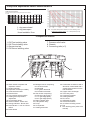
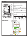
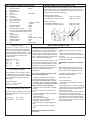
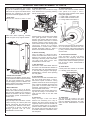
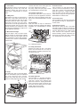
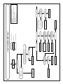
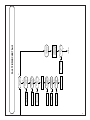
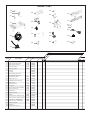
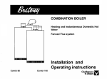
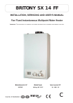
C
MAINTENANCE AND
SERVICE GUIDE
system II Plus 80 and 100
Central Heating
Fanned Flue Boiler
Dimensions
Sizes in mm
Boiler outer case dimensions :
- Height : 850
- Boiler width : 440 (minimum space required 450)
- Depth : 380
Flue types:
C 12 or 42: horizontal
C 32 xx:
vertical concentric
C 32 xy:
Twin flue
I
J
K
L
N
Safety valve outlet
Heating flow
H.W. flow
Gas supply
Heating return
Technical data
Heat input C/H & HW
System 80 :
System 100 :
Heat output C/H & HW System 80 :
System 100 :
Max. operating pressure C/H circuit :
Expansion vessel net capacity
:
:
Expansion vessel initial pressure
11.73 to 28,70 kW
15.43 to 34.50 kW
9.50 to 24 kW
12.50 to 28 kW
2.5 bar
5.4 l
0.7 bar
Electrical consumption
Voltage
Electrical protection index
Fuses
Gas category
:
:
:
:
:
150 w
230 v
IP24
2 A and 1.25 A
II 2H+ 3+
Nominal gas flow rate at 15°C and 1013 mbar
BRITONY System II Plus 80
Maximum
Minimum
power kW
power kW
BRITONY System II Plus 100
Maximum
Minimum
power kW
power kW
-Natural gas ( G 20) at 20 mbar
-Butane gas ( G 30 ) at 28 mbar
-Propane gas ( G 31 ) at 37 mbar
2.74 m3/h
2.04 kg/h
2.00 kg/h
3.34 m3/h
2.45 kg/h
2.42 kg/h
-Blue solenoid restrictor diameter
-Gas valve restrictor diameter
-Manifold injectors (16)
1.57 m3/h
1.17 kg/h
1.15 kg/h
11 mbar
35 mbar
26.7 mbar
12.8 mbar
30.4 mbar
24 mbar
BRITONY System II Plus 80
Butane or Propane
Natural gas
BRITONY System II Plus 100
Butane or Propane
Natural gas
-Nominal Burner Pressure (NG - G20)
-Nominal Burner Pressure (Propane L.P.G. - G31)
-Nominal Burner Pressure (Butane L.P.G. - G30)
Injectors and gas valves seat diameter
1.22 m3/h
0.91 kg/h
0.89 kg/h
2.60 mm
6.70 mm
1.23 mm
1.75 mm
4.90 mm
0.70 mm
2.90 mm
no restrictor required
1.26 mm
2.00 mm
6.70 mm
0.76 mm
Pump and expanssion vessel characteristics
PUMP HEAD AVAILABLE
disponible
MinimumPression
flow rate (with
all heating thermostatic valves closed)
mCE Débit mini (robinets thermostatiques fermés)
m CE
5
1
4
3
2
2
1
Flow
Débit
0
100
200
300
400
500
600
700
800
900
1000
1100 l/h
1 = by-pass closed
2 = by-pass open
Note : The system initial pressure should be over the following value :
System static height (in metre) + 0.7 = Initial pressure (in bar)
10
Head available / flow
Components location
7. Pressure relief valve
8. Chassis
9. Connecting tails (x 5)
1. CH Flow isolating valve
2. HW Flow isolating valve
3. Gas service tap
5. CH Return isolating valve
1
3
0
4
bar
8
1
10. Steel chassis complete with
expansion vessel
11. Sealed chamber
12. Expansion vessel (not visible)
13. Overheat thermostat
14. Electrical box
15. Two position selector switch
17. Heating flow temperature
adjustment
18. CH pressure gauge
20. Green indicator - Power ON
21. Orange indicator - Burner ON
22. Red indicator - Lock out / flame
failure
23. Reset button
2
2
3
9
5
24. Multigas burner comprising:
-25. 16 burner head
-26. Manifold
-27. 2 Ignition electrode
-28. Ionization electrode
29. Gas section comprising:
-30. Security valve (grey)
-31. 1/3 gas stage (blue)
-32. 2/3 gas stage (black)
33. Right hydraulic assy
34. Left hydraulic assy
35. Pump
36. Air separator
37. Heating thermistor
7
39. Combustion chamber made of
aluminium coated steel with 4
ceramic fibre panels to insure
heat insulation
40. Copper main exchanger
42. Three way valve
43. Connecting bracket
45. Heating flowstat
46. Flue hood
47. Adjustable by-pass
49. Air Pressure switch
50. 45° elbow including venturi
51. Fan
K. Flue kit fixing point (refer to kit
manual)
FUNCTIONING
Switching on
1) Check that the gas service tap is opened at the gasmeter and main
power is on.
2) Check that pressure in central heating system is above 0.7 bar and
COMPONENTS LOCATION
50
K
49
51
below 2.5 bar with the pressure gauge
18.
3) Open the gas tap 3 by turning from right to left.
12
4) The boiler is now ready to use.
Hot Water
10
1) Turn selector switch 15 to position
46
cator
40
The green "power on" indi-
(20) will light.
2) The orange "burner on" indicator
(21) will light and the cylinder-
will be heated.
11
Heating and Hot Water
25
1) Turn selector switch 15 to position
39
indicator
26
. The green "power on"
will light.(20)
2) If the room thermostat (if fitted), the boiler temperature control
24
and the clock (if fitted) are all calling for heat, the orange "burner
29
on" indicator
36
13
will light and the heating will be on.
Control panel
33
23
22
34
45
14
35
C
15
17
20
21
18
BRITONY System II plus
FUNCTIONAL DIAGRAM
50
51
49
40
39
28
27
24
13
29
12
14
32 31 30
45
37
42
36
35
47
5
1
2
3
7
43
Heating mode
storage
tank
3
When there is a need for hot water tank
reheating while the heating is on. The
heating will be interrupted momentarily
while tank is reheated. The boiler will
switch back automatically to heating
when the tank is at temperature.
Note: If the boiler has been turned off for
some time the first attempt to light it may
result in a lockout . 22 . If this happens
press the reset button 23 and the boiler
will light.
Domestic Hot Water Mode
To be able to supply hot water, the selector switch 15 must be in either on
or
position. This will be confirmed
20
by the green indicator light
When the aquastat of the tank is on, it
activates the DHW flow switch 44 and
allow the 3 way valve 42 to move to the
HW position. The pump can now circulate primary water heated by the main
heat exchanger through the tank heat
exchanger.
The first stage solenoid 31 (blue) and
security solenoid 30 (grey) open together
to allow gas to the burner. The ignition
sequence begins and a continuous high
speed spark ignites the gas. As soon as
a flame is detected the orange indicator
bulb
21 will light and the second stage
solenoid 32 (black) opens to allow the full
gas rate. If a flame is not detected, after
8 seconds, the security solenoid closes
and shuts off the gas. The red lockout
indicator bulb
22 will light. The water
flow temperature is controlled by the
central heating control thermistor 37.
When the tank is at temperature, the
burner is extinguished and the pump
stops. The boiler will now stay in the hot
water mode for three minutes.
Priority will be given to a demand for hot
water tank reheating. This will interrupt
the central heating for the duration of hot
water tank reheating.
Central Heating Mode
To be able to supply heating, the selector
position.
switch 15 must be on
This will be confirmed by the green indi20.
cator light
When there is a demand for heating
(either from the room thermostat or the
clock) the pump starts. If the boiler temperature control is calling for heat and
primary flow rate over 4 ltr/min, the central heating flow switch operates allowing
the ignition sequence to begin. The first
stage solenoid 31 (blue) and security
solenoid 30 (grey) open together to allow
gas to the burner. The ignition sequence
begins and a continuous high speed
spark ignites the gas. As soon as a flame
is detected the orange indicator bulb
21 will light. After 45 seconds the second
stage solenoid 32 (black) opens to allow
the full gas rate. If a flame is not detected, after 8 seconds, the security solenoid
closes and shuts off the gas. The red
lockout indicator bulb
22 will light.
The central heating flow temperature is
controlled by the central heating control
thermistor 37. The boiler has been
designed to minimise cycling and will not
attempt to relight for at least 3 minutes
after the boiler thermostat has been satisfied. When the room thermostat is satisfied the burner will switch off and the
pump will remain running for a further 3
minutes before it too stops.
NB
It is possible to override the 3 minute
delay by pressing the RESET button 23.
Lock out procedure
Flame disappearance :
When the ionisation electrode 28 does
not detect flame presence. The orange
indicator lamp 21 extinguishes. A lighting
cycle starts. If a flame is not detected
before 8 seconds, the grey security solenoid 30 and the blue 1/3 solenoid 31will
close. The lock out red indicator 22
lights, the pump 35 runs and the 3 way
valve 42 stays in its position.
After a few seconds, it will become possible to reset the boiler by pressing the
reset button 23.
Overheat detection :
If an overheat is detected by the sensor
13, the grey security solenoid 30 and the
blue 1/3 31 closes, the orange indicator
lamp 21 extinguishes. The ignitor is
energised for 8 seconds and the red
lockout indicator 22 ligths. If the burner
cannot relight the boiler will go to lockout.
WIRING
Plug for main power and Room
thermostat connection
DIAGRAM
1
2
3
4
5
1. Neutral
2. Phase
3. Room thermostat live
4. Accelerator resistor
5. Common for Accelerator and room
thermostat.
4
ELECTRICAL WIRING continuation
N°
13.
14.
14a.
14b.
14c.
14d.
14e.
14f.
14g.
18.
27.
28.
30.
31.
32.
35.
37.
38.
42.
44.
45.
51.
Designation
-Overheat sensor
-Electrical box
-Regulation PCB
-Ignitor
-Fuse 1.25 A
-Fuse 2A
-Power PCB
-Room thermostat
-Mains 230V 50 Hz
-Pressure switch
Wiring colours
Brown
Red, Black
2: Black P: Orange
1: White
-Spark electrodes
White
-Ionisation probe
White
-Security solenoid (grey)
Grey
-2/3 gas stage solenoid (black) Black
-1/3 gas stage solenoid (blue) Blue
-Pump
-C/H thermistor
Violet
-DHW thermistor
Green
-3 way valve
White, Yellow, Orange
-DHW flow switch
Brown
-C/H flow switch
Red
-Fan
Brown, Blue
REGULATION
Temperature regulation for both C/H and
DHW circuits are controlled by 2 thermistors. The C/H knob allows the adjustment
of temperature between 35 and 85°C. The
DHW temperature is limited to 60°C. DHW
and C/H thermistors are identical and
interchangeable.
Resistance value are
-5000 Ω at
25 °C
-2631 Ω at
40°C
-620 Ω at
80°C
-255 Ω at
110°C
FLOW SWITCHES
Flow in both D.H.W. and Heating circuits
are detected by 2 flow switches. A piston
with a magnet at the top operates a REED
switch. The piston is lifted by flow rates
listed below :
Flow rate threshold :
D.H.W.
120 l/h ±20 l/h
C/H 250 l/h ±20 l/h
AIR PRESSURE SWITCH
The air flow rate is detected by a pressure
differential created by a venturi located in
the flue duct.
ON threshold
OFF threshold
∆P > 130 Pa
∆P < 100 Pa
ADJUSTMENTS ON CONTROL PCB
The following adjustments are available on the regulation PCB. To
gain access to them, pivot down electrical box, remove the rear
cover and the rear panel of electrical box, unplug connectors from
regulation PCB and pull it toward you.
Heating output limitation :
- Functioning without limitation
- Functioning at 1/3 gas rate only
plug C on "P MAX"
plug C on "P 1/3"
Burner functioning:
- Regulation available 3/3, 1/3, 0
- Functioning at full gas rate only
plug D on "NOR"
plug D on "TUR"
D
C
ROUTINE SERVICING
To ensure continued efficient operation of
the appliance, it is recommended that it is
checked and serviced as necessary at
regular intervals. The frequency of servicing will depend upon the particular installation condition and usage, but in general,
once a year should be adequate.
It is the law that any service work must be
carried out by a competent person such
as your local Chaffoteaux Service Centre,
British Gas or other CORGI registered
personnel in accordance with the current
Gas Safety (Installation and Use)
Regulations.
- Check burner pressure and gas flow
rates.
- Check that the fan blades are clean.
- Check, clean and replace components as
necessary.
- Carry out combustion test utilising the test
points in the flue turret.
SUGGESTED SEQUENCE for SERVICING
Before disconnecting or removing any
parts, isolate the gas and electricity supplies. Ensure that the appliance is cool.
The service schedule should include
the following operations:
(for detail please see section on Parts
Removal and Replacement)
- Check the pressure in the system by
checking the reading on the pressure
guage (No. 18 Control Panel - Page 3).
- Check the correct operation of the appliance (see Page 4 - Domestic Hot Water
Mode and Central Heating Mode).
- Check the correct operation of the gas
controls.
- Check the functions of the safety controls.
- Check combustion chamber insulation
panels for damage.
- Clean the burner.
- Clean the heat exchanger.
- Check the burner manifold injectors.
- Clean gas and water filters.
- Check expansion vessel charge pressure.
- Clean and check operation of safety
valve.
Preliminary Checks
- Remove outer case
- Check the system pressure is at least
0.7 bar cold
- Check operation of 1/3 and 2/3 solenoids.
- Check that the burner is extinguished fully
when both solenoids are closed in both
DHW and C/H modes.
- Test ionisation functions and check that
lockout occurs by turning off gas tap.
- Whilst boiler is operating, check operation
of primary flow switch by closing heating
flow valve and by pass screw (turn clockwise) noting the number of turns so that it
may be reset correctly.
Additional Procedures that may be
necessary:
5
REMOVAL AND REPLACEMENT OF PARTS
Before removing appliance case, isolate
the gas and electrical supplies. Isolate
boiler from the system and drain before
removing any component in the waterways. Ensure that the appliance is cool.
1. Outer Case
Remove four screws in base of case
5. Ignition Electrodes
Carry out steps 1 and 2 as above. Hinge
down electrical box by pressing retaining
tabs P on either side.
P
10. Pressure Switch
Remove outer case and sealed chamber
front panel as in steps 1 and 2.
Disconnect three pressure switch cables
noting their positions.
1 = white cable connected to NC
2 = black cable connected to NO
P = orange cable connected to C
1
C
A A
A A
andlift free. When replacing, carefully
locate on lugs T on top edge of chassis.
T
T
T
T
1
2
P
Remove wiring cover C. Disconnect leads
from spark generator. Loosen screws
securing the closure plate and remove.
Remove grommet from base of sealed
chamber. Remove screw securing electrode bracket and lift clear easing spade
connectors through the grommet.
Reassemble in reverse order, twisted
together electrodes cable at least 10
times to avoid electrical interference.
6. Burner Assembly
Carry out steps 1,2, disconnect electrodes as mentionned in section 4 and 5.
Remove two screws securing burner
assembly to the back panel of the boiler.
Lift right hand back corner first.
Reassemble in reverse order.
7. Gas Solenoids
Disconnect colour coded leads. Remove
six screws. The solenoids are attached to
their base plate. Lift clear taking care not
to lose the three plungers and springs.
Reassemble in reverse order replacing
the cork gasket.
2. Combustion Chamber
Unscrew four self tapping screws securing the sealed chamber front panel and lift
over top corner locating lugs. Unscrew
four self tapping screws to release combustion chamber front plate and lift clear.
Reassemble in reverse order.
3. Burner Manifold
Carry out steps 1 and 2 as above.
Remove two screws securing the closure
plate and the remaining four screws to
release the manifold. Lift clear. Replace
the manifold gasket. Reassemble in
reverse order.
4. Ionisation Electrodes
Carry out steps 1 and 2 as above. Loosen
screws securing the closure plate and
remove. Disconnect the lead from the
main wiring loom. Remove screw securing electrode to burner. Thread wire
through grommet and lift clear.
Reassemble in reverse order.
6
2
8. Fan Assembly
Remove the outer case and sealed chamber front panel (See Steps 1 and 2).
Disconnect spade connectors noting
positions. Remove the screw securing the
front of the fan assembly and loosen the
grub screw on the flue outlet. Twist fan
assembly anticlockwise to disengage
from flue outlet and lift clear.
Re-assemble in the reverse order ensuring that the wiring is re-connected correctly and the screw on the flue outlet
tightened.
9. Flue Hood
Carry out steps 1 and 2 as above.
Remove fan assembly as in step 8.
Remove the three screws securing the
angled top of the hood to the chassis. Lift
and remove taking care not to snag the
pressure switch cables. Re-assemble in
the reverse order ensuring that the hood
is located behind the combustion chamber rear panel.
P
Remove screw securing the switch bracket to the chassis. Disconnect the sampling tubes again noting their positioning
(+ and -). Remove switch. Reassemble in
reverse order.
11. Pressure Switch Venturi
Carry out steps 1, 2 and 8, as above.
Disconnect the sampling tubes and
remove the screw securing the venturi to
the flue outlet. Remove venturi by the bottom of the 45° elbow. Reassemble in
reverse order.
12. Drain down
2 drain points are located on the boiler.
H = Heating circuit drain point
(air separator)
H
13. Water filter
The C/H filter is located in the right
hydraulic assembly. Remove the return
pipe as described previously and withdraw the filter. Reassemble in reverse
order.
14. Flow switch
Drain boiler as in step 12. Disconnect the
electrical plug, turn the top cover anticlockwise, remove the O-ring and the
brass piston. Reassemble in reverse
order.
15. 3-Way valve
Drain boiler as in step 12. Remove the 3
clips on the 3 way valve. Remove the clip
on the exchanger flow pipe. Pull the pipe
down then pull it out of the 3 way valve.
Disconnect the plug from the motor.
Unscrew the nut on the pipe between the
connecting bracket and the 3 way valve
and pull it toward you. Rotate the 3 way
valve body anti-clockwise to unclip it from
the left hydraulic assembly.
17. Main heat exchanger
Carry out steps 1 and 2 as above. Drain
boiler as in step 12. Remove the 2 clips E
located on return and flow pipes and pull
them downwards. Pull the main exchanger toward you to remove. Reassemble in
reverse order.
Unscrew the nut F of the return pipe from
the volute. Remove the clip G on
the pump volute and pull pump toward
you. Reassemble in reverse order.
19. Pressure relief valve
The pressure relief valve can be serviced
from the front of the appliance. Drain the
boiler first, undo the retaining screw and
pull out the valve.Reassemble in reverse
order.
20. Thermistor
Drain the boiler as step 12. Disconnect
the plug, remove the retaining clip pull the
thermistor out. Reassemble in reverse
order.
37
23. Power board
Carry out steps 1, 2, and open the electrical box cover as mentionned in step 5.
Undo the 4 screws of the electrical rear
panel and remove it. Unplug all cables
from the PCB, remove earth plug from
earth socket. Hang out the power board.
Reassemble in reverse order.
24. Control board
Pull out plastic knob from the front panel
and proceed as step 23. Reassemble in
reverse order.
25. Expansion vessel
Remove the casing as step 1 and drain
the boiler as step 12 above. Unscrew the
connecting tails nuts and lift out the boiler
from the wall. Place it on a side on the
floor. Remove the expansion vessel
bracket retaining screws, disconnect the
pipe from the vessel and pull ti toward
you. Reassemble in reverse order.
37 = Heating thermistor
21. Safety thermostat
Remove the casing as step 1 and hinge
down the electrical box as step 5.
Disconnect the 2 cables, pull out the sensor with the clip 13.
13
E
18. Pump
Drain boiler as in step 12. Pivot the electical box downwards. Open the electrical
box cover removing the 2 screws.
Remove the pump plug from the power
board and earth plug from earth socket.
G
F
Reassemble in reverse order.
22. Spark generator
Carry out steps 1, 2, and open the electrical box cover as mentionned in step 5.
Undo the 4 screws of the electrical rear
panel and remove it. Unplug electrodes
wires, remove the ignitor connector from
the PCB, remove earth plug from earth
socket. Hang out the ignitor.
Reassemble in reverse order.
7
8
Release pump rotor
- Replace control PCB or
driver PCB
- Check mains electrical
connection
- Check internal fuses
- Check connection between the
2 PCBs
No
No
Ok
Yes
No
Ok
No
Does the red LED
light ?
Replace driver or control PCB
Replace pump
Ok
Check that the pump
spins freely
Ok
Check voltage in the
pump electrical box
- Press the RESET button
Yes
Replace pressure switch
Replace heating thermistor
Check or replace main heat
exchanger. It could be fully
scaled
Replace heating flow switch
Does the pump run ?
No
- Press the RESET button to cancel the 3 min. delay.
- Ensure that external controls are calling for heat.
- Rotate heating control knob clockwise to the maximum position.
Does the green LED
light ?
Put the SELECTOR switch
on
position
Yes
No
No
No
No
No
Check voltage on the fan
Ok
Check air pressure
switch continuity
between P and 1
Ok
Check heating
thermistor
Ok
Check flow in the boiler
primary circuit
Ok
Check heating flow
switch
No
Does the fan run ?
means a group of actions
means an action
means a test or a choice
FAULT FINDING CHART Part 1
Ok
Yes
Replace fan assembly
Replace spark generator or
ignition electrods assembly
- Check pressure probes
or
- Check flue duct condition
or
- Replace pressure switch
Yes
No
Replace driver or control PCB
No
Does the spark
generator energize ?
Ok
Check air pressure
switch continuity
between P and 2
No
Could you hear the
spark generation ?
Yes
PLEASE CHECK THE FOLLOWING POINTS CAREFULLY BEFORE
GOING THROUGH THE FAULT FINDING CHART
- Gas pressure
- Electric mains
- Minimum water pressure in the heating circuit (over 0.8 bar)
- All isolating valves have been opened
- boiler air vented
- Check that the heating filter is clear.
9
Replace electrode assembly
Replace gas solenoïd
assembly
Replace driver PCB
Check if an overheat occur or
replace overheat sensor
Replace control or driver PCB
Replace control PCB because
orange LED is deffective
No
No
No
No
No
Yes
Replace driver PCB
Ok
Check the ionization
electrode
Yes
Is there a gas pressure
at manifold ?
Yes
Do the gas solenoïds
energize ?
Press the RESET button
Yes
Does overheat contact
close ?
Yes
Check flow in the boiler
primary circuit
No
Does the burner light
for more than
8 sec. ?
No
Does the orange LED
light ?
Yes
Replace control PCB
Yes
The boiler is OK
No
Does the orange LED
light ?
Wait until the return pipe
become hot then rotate
the heating control knob
anticlockwise to minimum
The heating outlet pipe
temperature rise
FAULT FINDING CHART Part 2
SHORT LIST
104
547
110
402
615
560
111
616
505
113
572
627
629
510
805
605
514
206
606
607
532
636
938
216
Key N°
Description
G.C N° Manf. Pt. N°
Type
FF FF
104
OVERHEAT THERMOSTAT 100°C
277783
110
IGNITION ELECTRODE ASSY
277788
1002801
111
IONIZATION ELECTRODE
277789
1002802
113
HEAT EXCHANGER
277790
1010017
HEAT EXCHANGER
E00606
206
216
1010572
1011136
FAN ASSY
1304720
FAN ASSY
1304721
AIR PRESSURE SWITCH KIT
1306697
1307335
AIR PRESSURE SWITCH KIT
402
SOLENOID VALVES KIT
E23494
81836
505
THREE-WAY VALVE
277833
1010000
510
THERMISTOR TEMP. SENSOR
277834
514
SHUNT PLATE
532
WATER THROTTLE
277846
547
GAS FILTER
263545
37309
560
AIR SEPARATOR HEAD ASSEMBLY
277857
1002653
572
PUMP UP 15/50 230V
E11662
1010612
605
CONNECTOR
277872
606
PRESSURE GAUGE
607
IGNITER
379075
1002105.20
615
PRINTED CIRCUIT BOARD OF POW.
277880
1010592
616
PRINTED CIRCUIT BOARD OF REGU. 277881
1010047
627
FUSE 250V 2A - TEMPORIZED
277883
1003456
629
FUSE 250V 1.25A - TEMPORIZED
277884
805
PRESSURE GAUGE
1303158
636
KNOBS SET
1305158
938
PRESSURE RELIEF VALVE
1020933
1000733
1010611
81471
1010349
1011046
1003635
100
BR
ITO
BR NY
ITO SY
NY STE
SY M
ST II
EM
II
80
..
..
..
.
.
.
.
.
.
..
..
..
..
..
..
..
..
..
..
..
..
..
..
..
..
..
..
Manf. date
from
to
Notes
Manufacturer:
Chaffoteaux & Maury - France
Commercial subsidiary:
MTS (GB) Limited
MTS Building
Hughenden Avenue
High Wycombe
Bucks HP13 5FT
Telephone:
Fax:
Internet:
E-mail:
(01494) 755600
(01494) 459775
www.chaffoteaux.co.uk
[email protected]
Technical Support Help Line:
Customer Service Help Desk:
0870 241 8180
0870 600 9888
Ref. 1309470B - 3/2004
Chaffoteaux & Maury are continuously improving their products and therefore reserve the right to change specifications without
prior notice and accepts no liability for any errors or omission in the information contained in this document.