1
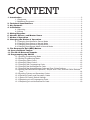
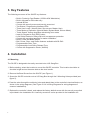
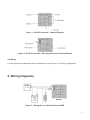
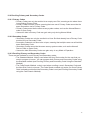
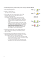
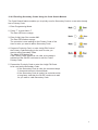
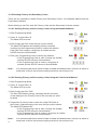
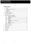
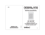
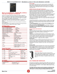
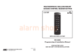
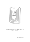
SA1DP
Instruction Manual
CONTENT
1. Introduction .............................................................................................................................3
1.1 Equipment ..................................................................................................................3
1.2 Additional Equipment ..................................................................................................3
2. Technical Specifications .....................................................................................................3
3. Key Features ...........................................................................................................................4
4. Installation ...............................................................................................................................4
4.1 Mounting .....................................................................................................................4
4.2 Wiring .........................................................................................................................5
5. Wiring Diagrams .....................................................................................................................5
6. Normal, Secure, and Master Users ..................................................................................6
7. Modes of Operation ...............................................................................................................7
8. Changing the Modes of Operation ....................................................................................8
8.1 Changing from Normal to Secure Mode .....................................................................8
8.2 Changing from Secure to Normal Mode .....................................................................8
8.3 Changing from Normal to Bypass Mode .....................................................................8
8.4 Changing from Bypass Mode to Normal Mode ...........................................................9
9. The Request to Exit (REX) Button ....................................................................................9
10. Case and Back Tamper .....................................................................................................9
11. The BL-40 External Sounder ..........................................................................................10
12. Programming the SA1DP .................................................................................................10
12.1 Entering Programming Mode ..................................................................................11
12.2 Exiting Programming Mode .....................................................................................11
12.3 Changing Open Code 1 ..........................................................................................12
12.4 Changing Open Code 2 ..........................................................................................12
12.5 Changing the Programming Code ..........................................................................13
12.6 Changing the Normal/Secure Code ........................................................................13
12.7 Changing the Normal/Bypass Code and Door Chime Settings ..............................14
12.8 Setting Fail Safe/Secure Operation, Tamper Siren Time, and Lock Strike Release
Time ........................................................................................................................14
12.9 Enrolling Primary and Secondary Codes ................................................................15
12.10 Deleting Primary and Secondary Codes ...............................................................18
12.11 Return to Factory Default Settings ........................................................................19
12.12 Replacing a Lost Programming Code ...................................................................19
12.13 Replacing a Lost Normal/Secure Code .................................................................19
1. Introduction
The SA1DP is a proximity card and keypad access control unit. The unit accepts up to 500 users
and provides entry via the use of proximity cards and/ or PIN codes.
1.1 Equipment
The following equipment is provided in every SA1DP package :
• SA1DP Access Control Unit
• Installation Kit
• Installation and Operating Instructions
1.2 Additional Equipment
The following additional equipment is required :
• Electric Lock Strike Mechanism - Fail Safe (Power to Lock) or Fail Secure
(Power to Open)
• Power Supply with Backup Battery - 12 to 16 V DC (from a regulated power
supply)
• Request to Exit (REX) button - Normally Open Type; Switch is closed when
pressed
• BL-40 External Sounder (optional) - Provides siren, bell, and chime function
to SA1DP
2. Technical Specifications
Electrical Characteristics
Operating Voltage Range12-16VDC
From a regulated power supply
Input Current
Standby : 40mA (excluding attached devices)
Max : 90mA (excluding attached devices)
Relay Outputs
Lock Strike Relay - Electronic, 3.5A with built-in suppressor
protection
Inputs
REX - N.O., Dry Contact
LEDs
Two tri-colored LEDs
Built-in Proximity Reader
Read Range* - 3.5” (90mm)
Modulation - ASK at 125kHz
Compatible Cards - All 26-Bit EM Cards
Environmental Characteristics
Operating Temperature
-25°F to 145°F (-31°C to 63°C)
Operating Humidity
0 to 95% (Non-Condensing)
Dimensions
3.62” (92mm) L x 3.62” (92mm) W x 0.94” (24mm) D
Weight
0.29 lbs (130g)
3
3. Key Features
The following are some of the SA1DP key features :
• Built-in Proximity Card Reader (125KHz ASK Modulation)
• Built-in Keypad for PIN code entry
• Internal Buzzer
• Comes with security screw and security screw tool
• Two Status / Programming Interface LEDs
• Three User Levels ( Normal User, Secure user, Master User)
• Three Modes of Operation (Normal Mode, Bypass Mode, Secure Mode)
• ”Code Search” feature simplifies maintaining user codes
• Input for Request to Exit (REX) button
• Lock Strike Electronic Relay with built-in suppressor protection
• Comes with mounting template for easier installation
• Built-in Case and Back Tamper
• Bell, Chime, Siren, and Strobe features available with BL-D40
• Programmable Siren Time
• Programmable Lock Strike Release Time
• Comes with Suppression Diode (1N4004)
4. Installation
4.1 Mounting
The SA1DP is designed to be easily mounted onto a US Gang Box.
1. Before starting, select the location to mount the SA1DP controller. This location should be at
shoulder height and on the same side as the door handle.
2. Remove the Bezel Screw from the SA1DP (see Figure 1).
3. Screw the SA1DP controller onto a US Gang Box through the 2 Mounting Holes provided (see
figure 2).
4. Pass the wires through the exit/entry holes and attach them to the controller’s terminal blocks, as
shown in the wiring diagrams. (See Figure 3 & 4 in Wiring Diagrams for wiring diagrams of
common installations).
5. Replace the controller’s bezel, and replace the factory default screw with the security screw that
is provided in the Installation Kit. A security screw tool is also provided in the Installation Kit.
4
Figure 1 : SA1DP Controller - Labeled Diagram
Figure 2 : SA1DP Controller - Mounting Holes and Terminal Blocks
4.2 Wiring
2 of the typical wiring diagrams are illustrated below (see Figure 3 & 4 in Wiring Diagrams).
5. Wiring Diagrams
SA1DP
Figure 3 : Wiring the Lock Strike Relay and REX
5
SA1DP
Figure 4 : Wiring the BL-D40 External Sounder
6. Normal, Secure, and Master Users
The SA1DP accepts up to 500 users and provides entry via the use of proximity cards and/or PIN
codes. Each user is provided with two code memory slots : Memory Slot 1 (Primary Code) and
Memory Slot 2 (Secondary Code). The two Memory slots can be programmed as Proximity Cards,
PIN codes, or as a combination of both Proximity Cards and PIN codes.
The way that the two memory slots are programmed determines a user’s access level and also
determines the way that the SA1DP grants access in its three modes of operation.
There are three user levels :
Normal User - A Normal User only has a Primary Code and is only Granted access when the
SA1DP is in Normal or Bypass mode.
Secure User - A Secure User must have a Primary and Secondary Code programmed; the two
codes must not be the same. The Secure User can gain access when the SA1DP is in any of its
three modes of operation. In Normal mode, the Secure User must present both a Primary and
Secondary Code in order to gain entry.
Master User - A Master User must have both Primary and Secondary Codes programmed with the
same Proximity Card or PIN code. The master User can gain access during any mode of operation
by presenting a Proximity Card or PIN code to the controller. (The Master User is convenient, but is
less secure than a Secure User).
6
7. Modes of Operation
The SA1DP has three modes of operation :
• Normal mode - Model LED is green.
Normal Mode is the default mode. In Normal Mode, the door is locked until a Primary Code is
presented to the controller. Special codes such as “Open Code 1” and “Open Code 2” are active in
Normal mode (See Changing Open Code 1 and Changing Open Code 2).
• Bypass mode - Mode LED is orange.
In Bypass Mode, access to the premises is dependent on whether the controller’s Lock Strike
Relay is programmed for Fail Safe Operation or for Fail Secure Operation.
When the Lock Strike Relay is programmed for Fail Secure Operation, the door is locked until the
Door Bell Button is pressed. When the Lock Strike Relay is programmed for Fail Safe Operation,
the door is constantly unlocked.
• Secure mode - Mode LED is red. Only Secure and Master Users can access the premises during
the Secure Mode.
A Secure User must enter a Primary and a Secondary Code in order to gain entry. After entering
the Primary Code, the Door LED flashes green for 10 seconds, during which time the Secondary
Code must be entered. A Master User only needs to present a proximity Card or PIN code once in
order to gain entry.
7
8. Changing the Modes of Operation
8.1 Changing from Normal to Secure Mode
For the Normal Mode, the Mode LED is green
The default factory setting for the Normal/Secure Code is 3838.
1. Enter the 4-digit Normal/Secure Code.
The Mode LED flashes red.
2. Press the # key to confirm the mode change.
The Mode LED turns red.
8.2 Changing from Secure to Normal Mode
For the Secure Mode, the Mode LED is red.
1. The default factory setting for the Normal/Secure Code is 3838.
2. Enter the 4-digit Normal/Secure Code.
The Mode LED flashes green.
3. Press the # key to confirm the mode change.
The Mode LED turns green,
8.3 Changing from Normal to Bypass Mode
For the Normal Mode, the Mode LED is green.
See Changing the Normal/Bypass Code and Door Chime Settings
to create/modify the Normal/Bypass Code.
1. Enter the 4-digit Normal/Bypass Code.
The mode LED flashes orange.
2. Press the # key to confirm the mode change.
The Mode LED turns orange.
8
8.4 Changing from Bypass Mode to Normal Mode
For the Bypass Mode, the Mode LED is orange
See Changing the Normal/Bypass Code and Door Chime Settings
to create/modify the Normal/Bypass Code.
1. Enter the 4-digit Normal/Bypass Code.
Mode LED flashes green.
2. Press the # key to confirm the mode change.
Mode LED turns green.
9. The Request to Exit (REX) Button
The REX button is used to open the door without the use of a proximity card or PIN code, and must
be located inside the premises in order to be secured. IT is usually located in a convenient location,
such as inside the door or at a receptionist’s desk. The function of the REX button depends on
whether the Lock Strike Relay is programmed for Fail Safe Operation or for Fail Secure Operation.
The door chime in the BL-D40 does not sound when the REX button is used to open the door.
• Fail Secure Operation : From the moment the REX button is pressed, the door remains
unlocked until the “Lock Strike Release Time” has passed. After this time, the door is
locked even if the REX button has not been released.
• Fail Safe Operation : From the moment the REX button is pressed, the door remains
unlocked until the REX button is released and the “Lock Strike Relay” only begins its
countdown once the REX button has been released.
10. Case and Back Tamper
If the case of the controller is opened or the controller is removed from the wall, a tamper event is
triggered and a coded tamper signal is sent to a BL-D40, PS-X41 Series or PS-X42 Series Power
Supply, or to another compatible device.
If the BL-D40 External Sounder, PS-X41 Series, or PS-X42 Series Power Supplies receives a Tamper
Event Signal, it activates a Siren, and if available, a Strobe Light. The Siren time can be easily
programmed in the SA1DP from zero to nine minutes.
You can clear a tamper event by entering a valid User or Open Code to open the Lock Strike Output
in the current Mode of Operation. For example, while in Secure Mode, you cannot use the Open
Code to clear the tamper event, because the Open Code does not work in Secure Mode. However,
you can apply a Master Code or Secure Code to clear the tamper event in Secure Mode.
9
11. The BL-D40 External Sounder
The BL-D40 External Sounder is compatible with the SA1DK, SA1DP, AC-X41, and AC-X42 series
Standalone Controllers. It is designed to operate indoors and is installed within the premises to be
secured. The Sounder can be powered by a 16V AC or 12 to 24V DC power supply.
The BL-D40 is capable of emitting four different types of alerts, both audible and visual : Bell, Door
Chime, Siren, and Strobe Light.
• The Bell always sounds when the controller’s doorbell button is pressed.
• The Door Chime can be programmed to sound whenever the controller unlocks the door
(the Door Chime does not sound when the REX button is used to open the door).
• The Siren can be programmed to sound when the case of the controller is opened or
when the controller is removed from the wall. The controller can also program the length
of the Siren in the BL-D40.
The Controller communicates with the BL-D40 using a coded proprietary communications protocol.
This provides a more secure link between the Controller and the BL-D40. If the BL-D40 receives
any unrecognized codes on its communication line, or communication between the controller
and the BL-D40 are severed, the Strobe flashes repeatedly until the communication problem is
resolved.
12. Programming the SA1DP
You can program the SA1DP solely via the unit’s keypad-driven Programming Menu System. To
reach the Programming Menu System, first place the SA1DP into Programming Mode (see Entering
Programming Mode for more information).
During the SA1DP manufacturing process, certain codes and settings are preprogrammed. These
settings are called the “Default factory Settings”.
The Table below shows the names of all the SA1DP Menus. It also shows all the SA1DP default
factory codes and settings.
Table 1 : Programming Menu
Menu Number
1
2
3
4
5
6
7
8
0
Menu Description
Change Open Code 1
Change Open Code 2
Change Program Code
Change Normal / Secure Code
Change Normal / Bypass Code
Change Door Release Time
Enroll Proximity Cards, PIN Code, or both
Delete Proximity Cards or PIN Code
Return to Default Factory Setting
Factory Settings
2580
0852
1234
3838
N/A
004
A complete description and instructions for each of the above menu items is detailed on the following pages.
10
12.1 Entering Programming Mode
1. Press the # key for two seconds.
The Mode LED turns off and the Door LED turns red.
2. Enter your 4-digit Programming Code.
If the Programming Code is valid, the door LED turns
green and the SA1DP goes into Programming Mode.
Note : The SA1DP must be in Normal Mode in order to enter the Programming Mode.
Programming Mode.
The factory default Programming Code is 1234.
If a Programming Code is not entered within 5 seconds, the SA1DP returns to Normal
Mode.
12.2 Exiting Programming Mode
To exit the Programming Mode at any time:
1. Press the # key for two seconds.
3 beeps are emitted.
The Door LED turns off.
The Mode LED turns green, indicating that the SA1DP has returned to Normal Mode.
Note : Wrong entries may reset the controller back to Normal Mode.
While in Programming Mode, if no key is pressed for one minute, the SA1DP exits
programming mode and returns to Normal Mode.
In certain Programming Modes, a quick press on the # key may also return the system
to Normal Mode.
11
12.3 Changing Open Code 1
Open Code 1 is mainly used as a method to quickly test the Lock Strike Relay during installation.
The Default Factory Setting for Open Code 1 is 2580.
When the first use is added to the controller, the default Open Code is automatically deleted, and
is ready for a new Open Code 1 to be reentered.
1. Enter Programming Mode.
2. Press “1” to enter Menu 1.
The Mode LED turns red.
3. Enter the new 4-digit code that you want to set as Open Code 1.
• The Door LED turns off.
• The Mode LED turns green.
Note : Open Code 1 does not function is Secure Mode.
Wrong entries return the controller to Normal Mode.
Code 0000 erases and deactivates the Open Code.
12.4 Changing Open Code 2
Open Code 2 is mainly used as a method to quickly test the Lock Strike Relay during installation.
The Default Factory Setting for Open Code 1 is 0852.
When the first use is added to the controller, the default Open Code is automatically deleted, and
is ready for a new Open Code 2 to be reentered.
1. Enter Programming Mode.
2. Press “2” to enter Menu 2.
The Mode LED turns orange.
3. Enter the new 4-digit code that you want to set as Open Code 2.
The system returns to Normal Mode :
• 3 beeps are emitted.
• The Door LED turns off.
• The Mode LED turns green.
Note : 12
Open Code 2 does not function is Secure Mode.
Wrong entries return the controller to Normal Mode.
Code 0000 erases and deactivates the Open Code.
12.5 Changing the Programming Code
1. Enter Programming Mode.
2. Press “3” to enter Menu 3.
The Mode LED turns green.
3. Enter the new 4-digit code that you want to set as the
Programming Code. The system returns to Normal Mode:
• 3 beeps are emitted.
• The Door LED turns off.
• The Mode LED turns green.
Note : Programming Code cannot be erased, meaning that the code 0000 is not valid and does
not erase the programming Code.
12.6 Changing the Normal/Secure Code
1. Enter Programming Mode.
2. Press “4” to enter Menu 4.
The Mode LED flashes red.
3. Enter the new 4-digit code that you want to set as
Normal/Secure Code. The system returns to Normal Mode:
• 3 beeps are emitted.
• The Door LED turns off.
• The Mode LED turns green.
Note : When the Auxiliary Mode is 1, 2, 3, or 4, the Auxiliary Input takes priority over the
Normal/Secure Code.
13
12.7 Changing the Normal/Bypass Code and Door Chime Settings
The Normal/Bypass Code is also used to turn the Door Chime off and on.
1. Enter Programming Mode.
2. Press “5” to enter Menu 5.
The Mode LED flashes orange.
3. Program the Normal/Bypass Code and Door Chime in
one of the following four different ways:
• Disable the Bypass Mode and disable the Door Chime:
Enter the 4-digit code 0000.
• Disable the Bypass Mode and enable the Door Chime:
Enter the 4-digit code 0001.
• Enable the Bypass Mode and disable the Door Chime:
Enter any 4-digit code ending with 0.
• Enable the Bypass Mode and enable the Door Chime:
Enter any 4-digit code not ending with 0.
The system returns to Normal Mode:
• 3 beeps are emitted.
• The Door LED turns off.
• The Mode LED turns green.
Note : The Door is only generated when the Lock Strike Relay is activated due to a valid code
entry.
12.8 Setting fail Safe/Secure Operation, Tamper Siren Time, and Lock Strike Release Time
1. Enter Programming Mode.
2. Press “6” to enter Menu 6.
The Mode LED flashes green.
3. Construct the 4-digit code using the following instruction.
• First digit : For Fail Secure Operation, enter a “0”;
For Fail Safe Operation, enter a “1”.
• Second digit : Tamper Siren Time; enter the number
of minutes (from “1” to :9:).
• Third and fourth digit : Lock Strike Release Time;
enter the number of seconds (from “1” to “99”)
after which you want the Lock Strike to be released.
For example : 0 5 1 2 means Fail Secure Operation, with a 5 minute Tamper Siren Time, and a
12 second Lock Strike Release Time.
The system returns to Normal Mode:
• 3 beeps are emitted.
• The Door LED turns off.
• The Mode LED turns green.
14
12.9 Enrolling Primary and Secondary Codes
12.9.1 Primary Codes
• Primary Codes can only be enrolled to an empty user Slot, meaning a slot where there
is no existing Primary Code.
• Primary Codes must be unique, meaning that one user’s Primary Code cannot be the
same as another user’s Primary Code.
• Primary Code cannot be the same as any system codes, such as the Normal/Secure
code or Open Code.
• Users who hold a Primary Code can gain entry only during Normal Mode.
12.9.2 Secondary Codes
• Secondary Codes can only be enrolled to a User Slot that already has a Primary Code
enrolled, but no Secondary Code.
• Secondary Codes do not have to be unique, meaning that multiple users can all hold the
same Secondary Code.
• Secondary Codes cannot be the same as any system codes, such as the Normal/
Secure Code or Open Code.
• Users who hold Secondary Codes can gain entry in any Mode of Operation.
12.9.3 Enrolling Primary and Secondary Codes
There are two methods to enroll Primary and Secondary codes;
• The Standard Method : Mainly used when the User Slot number for the user that you
want to program is known. You can program both Primary and Secondary Codes using
the Standard method (see Enrolling Primary and Secondary Code Using the Standard
Method).
• The Code Search Method : mainly used when enrolling a user’s Secondary Code and
the User Slot Code is unknown. The Code Search method only works if a users Primary
Code is already enrolled but the Secondary Code is not (see Enrolling Secondary Codes
using the Code Search Method).
15
12.9.4 Enrolling Primary and Secondary Codes using the Standard Method
1. Enter Programming Mode.
2. Press “7” to enter Menu 7.
The Door LED turns orange.
3. Enter 3-digit User Slot number between 001 to 500
to indicate the user to who you want to enroll a
Primary or Secondary code.
For example, the User Slot 003 represents User #3.
• If the selected slot does not have a Primary
Code, the Mode LED flashes green, indicating
that the controller is ready to accept a Primary
Code.
• If the selected slot already has a Primary Code
but does not have a Secondary Code, the Mode
LED flashes red, indicating that the controller is
ready to accept a Secondary Code.
• If the selected slot already has a Primary and
Secondary Code, a long beep is emitted and
the controller returns to Normal Mode.
4. Present a proximity Card, or enter 4-digit PIN that you
want to assign as the Primary or Secondary Code for
this slot number.
5. If the Proximity Card or PIN that is entered is valid, the
Mode LED stops flashing and the controller is now ready.
You can either continue or stop enrolling codes.
• To enroll a code, enter the next 3-digit slot number
that you want to assign a code to, or press the # key
to move to the next slot number.
• To stop enrolling codes, press the # key for two
seconds to return the controller to Normal Mode.
16
12.9.5 Enrolling Secondary Codes Using the Code Search Method
The Code Search feature enables you to quickly enroll a Secondary Code to a user who already
has a Primary Code.
1. Enter Programming Mode.
2. Press “7” to enter Menu 7.
The Door LED turns orange.
3. Enter 3-digit User Slot number 000.
The Door LED flashes orange.
The controller is now waiting for the Primary Code of the
User for who you want to add a Secondary Code.
4. Present a Proximity Card, or enter 4-digit PIN Code of
the Primary Code belonging to the user for who you
want to add a Secondary Code.
The Mode LED flashes red.
If the Primary Code entered is not valid, a long beep is
emitted and the SA1DP continues to wait for a valid
Primary Code.
5. Present the Proximity Card or enter the 4-digit PIN Code
to be used as the Secondary Code.
• If the Secondary Code is valid, the controller beeps
3 times and returns to Normal Mode.
• If the Secondary Code is invalid, he controller emits
a long beep, and then the SA1DP continues to wait
for you enter a valid Secondary Code.
17
12.10 Deleting Primary and Secondary Codes
There are two methods to delete Primary and Secondary Codes : the Standard Method and the
Code Search Method.
When deleting a user Slot, both the Primary Code and the Secondary Code are erased.
12.10.1 Deleting Primary and Secondary Codes using the Standard Method
1. Enter Programming Mode.
2. Press “8” to enter Menu 8.
The Mode LED turns red.
3. Enter 3-digit User Slot codes that you want to delete.
The Mode LED flashes red indicating that the controller
is waiting for the Programming Code to confirm the deletion.
If the User Slot is empty, a long beep is emitted and the
SA1DP returns to Normal Mode.
4. Enter your Programming Code to confirm the deletion.
• If the Programming Code is valid, 3 beeps are emitted,
and the SA1DP returns to Normal Mode.
• If the Programming Code is invalid, a long beep is
emitted, and the SA1DP returns to Normal Mode.
Note :
It is recommended that a record be kept of added and deleted users, so that it is easier to
keep track of which user slots are empty and which user slots are not.
12.10.2 Deleting Primary and Secondary Codes Using the Code Search Method
1. Enter Programming Mode.
2. Press “8” to enter Menu 8.
The Mode LED turns red.
3. Enter 3-digit User Slot “000”.
The Door LED flashes orange, indicating that the controller
is now waiting for the Primary Code of the user that you want
to delete.
4. Present the Proximity Card or enter the 4-digit PIN Code of
the Primary Code belonging to the user that you want to delete.
The Mode LED flashes red.
• If the Programming Code is valid, 3 beeps are emitted,
and the SA1DP returns to Normal Mode.
• If the Programming Code is invalid, a long beep is emitted,
and the SA1DP returns to Normal Mode.
Note :
18
It is recommended that a record be kept of added and deleted users, so that it is easier to
keep track of which user slots are empty and which user slots are not.
12.11 Return to Factory Default Settings
WARNING!! Be very careful before using this command as it will erase the entire memory,
including all User and Special Codes, and will return all codes to their factory default settings.
1. Enter Programming Mode.
2. Press “0” to enter Menu 0.
The Mode LED and the Door LED flash red.
3. Enter your 4-digit Programming Code.
If the Programming Code is valid, all memory
is erased, 3 beeps are emitted, and the controller
returns to Normal Mode.
• If the Programming Code is invalid, a long
beep is emitted, and the controller returns
to Normal Mode without erasing the memory
of the controller.
12.12 Replacing a Lost Programming Code
Note : In order to be able to replace a lost programming code, the SA1DP must be in Normal
Mode. Before proceeding, verify that the Mode LED is green.
1. Remove power from the SA1DP
2. Press the REX button.
3. Apply power to the unit while pressing the REX button.
4. Release the REX button.
5. Program a new Programming Code into the unit using the initial default code 1234. You have 15
seconds to do so, before the controller reverts to the existing code.
12.13 Replacing a Lost Normal/Secure Code
Note : In order to be able to replace a lost Normal/Secure code, the SA1DP must be in Secure
Mode. Before proceeding, verify that the Mode LED is red.
1. Remove power from the SA1DP
2. Press the REX button.
3. Apply power to the unit while pressing the REX button.
4. Release the REX button.
5. Program a new Normal/Secure Code into the unit using the initial default code 3838. You have 15
seconds to do so, before the controller reverts to the existing code.
19