1
F007F007-EM Fingerprint&
Fingerprint& RFID Access Controller
User Manual
Sebury Technology Co.,Ltd
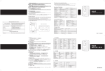
F007-EM Simplified Instruction
Function description
Choose from the relevant functions below and input
Enter the programming mode
*- 888888 - #,
then you can do the programming
(888888 is the default factory master code)
change the master code
0 - new code - # - repeat the new code - #
(code: 6-8 digit)
Add fingerprint user
1– Fingerprint – repeat Fingerprint - #
(can add Fingerprints continuously)
Add card user
1– Card - #
(can add Cards continuously)
Delete user
2 – Fingerprint - #
2 – Card -#
(can delete Users continuously)
Exit from the programming mode
*
How do release the door
Fingerprint User
Put the Finger on the fingerprint sensor for 1 second
Card User
Read card
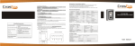
F007- EM Fingerprint& RFID Access Controller
1, Introduction
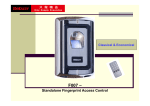
F007-EM is the new member of F Series Standalone Fingerprint access control, as
traditional it is in metal shell, anti-vandal, supports fingerprint, besides, F007-EM
support RFID card (125KHZ EM card) and wiegand interface. The high security and
more powerful feature make it an ideal choice for door access.
User capacity 2160, including 160 fingerprint users and 2000 RFID card users.
With the flexible user capacity, it is suitable to be installed from small house such as
personal rooms, shops, office to public place such as large factories, companies.
By Remote control or Master card for programming, it is so user friendly that anyone
can use it.
2, Main Feature;
Metal shell, anti-vandal
User capacity: 2160
160 Fingerprint users, 2000 RFID card users
Wiegand 26 output; wiegand 26 input
Besides standalone, it can connect to other controller as the salve reader
2 pcs F007-EM can interconnect; 2 pcs F007-EM can be interlocked;
Remote infrared programmer; Manager card for programming
Anti-magnetic & lock output current short protect;
So easy for connection of the lock: only 2 wires output, selecting lock type by
programming menu;
Support connecting any card readers with wiegand interface, such as HID, Mifare,
EM
Full of 2160 users, searching speed <0.1 S.
3, Install, wiring and fixation
3.1, Install and wire
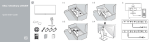
Open the real plate from the front cover
Drill 4 holes on the wall for screws and 1 hole for cable.
Fix the real plate on the wall firmly with 4 flat head screws.
Thread the cable through the cable hole, wiring, plug the cable harness
Attach the front cover to the real plate
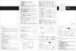
Terminal Wire Connector Function
1
D0
2
Green
D1
3
White
OPEN
5
D_IN
Wiegand output, input signal wire D1
connecting to the negative pole of the alarm equipment
ALARM Grey
4
Wiegand output, input signal wire D0
Yellow
Brown
To connect to one part of Exit Button
Door Contact input,
6
12V
7
GND
8
VSS
Red
Black
Blue
(+) 12Vdc Positive Regulated Power Input
(-) Negative Regulated Power Input
the negative pole of the controller, connect to the other part of Exit
button and door contact
9
L-
10
L+/Alarm+
Purple
Orange
Connect to the negative pole of the Lock
Connect to the positive pole of the lock and alarm equipment
Note: Do not power on until all wiring has been completed.
3.2 Intramural interface circuit
3.3 Method of Reset to Factory default setting and re-register Manager cards
Power off, press the RESET key (SW14) on the PCB, hold it and power on, release it until hear
two short beeps, the LED shines in orange, then read any two EM cards, after that the LED turns
in red, means reset to factory default setting successfully. Of the two EM cards read, the first one
is Manager add card, the second one is Manager delete card.
Remarks: Reset to factory default setting, the users’ information enrolled is still retained. When
reset to Factory setting, the two Manager cards must be re-enrolled.
3.4 Connection diagram
Remark:
F007-EM can connect both types of the locks directly, no matter it’s Fail secure (unlock when
power on) or Fail safe (unlock when power off). Please check Manager Operation – Item 5 for the
lock setting.
4, Manager Operation
There are 3 ways to add and delete users: 1, by Manager card; 2, by remote control; 3, by
Manager fingerprint
1, By Manager Card (the most convenient way)
1.1 Add Fingerprint user
st
nd
Manager add card
Enter 1 User Fingerprint Twice
2 User Fingerprint
Twice … Manager add card
Note: When add fingerprint, please input each fingerprint twice, during which the LED shines
red then turn green, means the Fingerprint is enrolled successfully. When delete fingerprint, just
input it once
1.2 Add Card user
st
nd
Manager add card
1 User card
2 User card … Manager add card
Remark:Fingerprint user ID is 3-162, Card user ID is 163~2162,when add fingerprint or
Card by Manager card, it is produced automatically from 3-160 or 163 to 2162. (ID 1, 2 are
belong to Manager fingerprint)
1.3 Delete users
Manager delete card
card OR Fingerprint once … Manager delete card
To delete more than 1 card or fingerprint, just input card or fingerprint continuously.
Note: When delete fingerprint, please input it once.
2, By Remote Control
Enter into programming mode:
*
Manager Password # . Default Manager Password: 888888
Remarks: All the steps below must be done after enter into programming mode.
2.1 Change Manager Password:
:
0
New Password #
Repeat New Password #
Remark:The manager password must be 6~8 digit number.
2.2 Add Users:
:
a) ID number – Auto generation
To add fingerprint users: 1
input one fingerprint twice #
(To add more than one fingerprints, just input finger continuously)
To add card users:1
Card # Or 1 the Card Number (8 digit) #
(To add more than one card, just input cards or Card number continuously)
Note: when add card users, it can just enroll the card number and don’t have to enroll the card
itself. The card number is the 8 digit printing on the card.
In the same way, when delete card users, it can just enroll the card number to delete it
and don’t have to get the card if it is lost.
b) ID number – Appointment
To add fingerprint users: 1 ID number # User Fingerprint #
(Fingerprint User ID number can be any digit between 3- 162, but one ID number to one
user)
To add fingerprint users continuously:
1 3 # 1st User Fingerprint 4 # 2nd user fingerprint …..N
# Nth user fingerprint #
To add card users: 1 ID number # Card #
Or 1 ID number # the Card Number (8 digit) #
(Card User ID number can be any digit between 163- 2162, but one ID to one Card)
To add card continuously: 1 163 # 1st Card 164 # 2nd Card…..N # Nth Card #
Or 1 163 # 1st Card Number 164 # 2nd Card Number…..N # Nth Card Number #
2.3 Delete users:
Delete fingerprint users: 2 fingerprint once #
Delete card users:2 Card # Or 2 Card Number #
To delete users continuously: just input fingerprint or card continuously
If delete users by ID
2 User ID #
Remarks: When delete users, the Master can just delete its ID number and don’t
have to input fingerprint or card. It is the good option to delete if the users were left
or cards lost.
2.4 To save and exit from the programming mode: *
3, By Manager Fingerprint
Enter into programming mode:
*
Manager Password
Add Manager fingerprint:
1
1
#
#.
input fingerprint twice 2
#
input another fingerprint twice
*
ID number 1: Manager add fingerprint
ID number 2: Manager delete fingerprint
The first Fingerprint: Manager add Fingerprint, it is to add the users
.
The second Fingerprint: Manager delete Fingerprint, it is to delete users
To add user:
Fingerprint: Manager add Fingerprint Input User Fingerprint twice Repeat Manager add
Fingerprint
Card: Manager add Fingerprint Card Repeat Manager add Fingerprint
To add users continuously
Fingerprint: manager’s add fingerprint 1st user fingerprint
User Fingerprint Manager’s add fingerprint
Card: Manager add Fingerprint Card 1 Card 2
2nd user fingerprint ….Nth
…… Repeat Manager add Fingerprint
To delete Fingerprint users
manager’s delete fingerprint 1st user fingerprint
Fingerprint Manager’s delete fingerprint
2nd user fingerprint ….Nth User
To delete Card users
Manager’s delete fingerprint
Card 1
Card 2
Manager’s delete fingerprint
4. Delete all the users
*
manager password # 20000 # *
Note: This will delete all fingerprints, cards, including Manager Fingerprint but except
Manager Card, before this operation it is suggested to make sure the data is un-useful.
5, Lock style setting and door relay time setting
Fail secure (unlock when power on) : *
manager password # 4
0~10
#*
Fail safe (unlock when power off): *
manager password # 5
1~10
#*
Remarks: In programming mode, press 4 is to choose Fail secure lock, 0-10 is to set door relay
time 0-10 seconds; press 5 is to choose Fail safe lock, 1-10 is to set door relay time 1- 10 seconds.
(Factory default setting is Fail safe lock, relay time 5 seconds.)
6 Setting - Door open detection
*
manager password # *
6
0
# to disable this function (factory default setting)
6
1
# to enable this function
When enable this function:
a)
If open the door normally, but not closed after 1 minute, the inside Buzzer will alarm
automatically, the alarm will be off itself after 1 minute
b)
If the door was opened force, or the door was not opened in 20 seconds after lock was
released, the inside Buzzer and outside Siren will both alarm.
7. Setting - Security Status
*
manager password #
Normal status: 7
0
# * (Factory default setting)
Lock on status: 7
1
# *In 10 minutes, if there’s 10 times invalid card or wrong
Password, the device will lock on for 10 minutes.
Alarm status: 7
2
# *In 10 minutes, if there’s 10 times invalid card or wrong
Password, the device will alarm.
8 Remove Alarm
When the device is in alarm ( from built-in buzzer, alarm equipment outside), to remove it:
Read valid user’s card or fingerprint or Manager Fingerprint or card or Manager Password # (Any of the method above can remove the alarm.)
9 Two devices interlock setting
*
8
8
manager password #
0
# * to disable this function (factory default setting)
1
# * to enable this function
10 Setting Alarm signal output time
*
manager password # 9
0~3
# *
Alarm time is 0-3 minutes for option, factory default setting 1 minute.
5, User Operation
User to release the door
Card user: Read card
Fingerprint user: Input Fingerprint
6, Sound and Light indication
Operation Status
Reset to factory default
setting
LED
Orange
Finger Sensor
Buzzer
-
Two short ring
Sleeping mode
Red shines slow
-
-
Stand by
Red shines slow
Shine
-
Enter into programming mode
Red shines
-
Short Ring
Exit from programming mode
Red shines slow
-
Short Ring
-
-
Three short ring
-
Short Ring
-
Alarm
Wrong operation
Open the door
Alarm
7, Technical sheet
Green shines
Red shines fast
Supply Voltage
Sleeping Current
Stay Current
Temperature
Humidity
Memory capacity
Fingerprint capacity
Card capacity
Card type
Card reading distance
Lock output load capacity
Alarm output load capacity
Resolution
Fingerprint input time
Identification time
FAR
FRR
Dimensions
N/W
G/W
12VDC±10%
<20mA
<90mA
-15℃-60℃
20%RH-95%RH
2160
160
2000
125KHZ ID card
50 ± 30 mm
20A
20A
450 DPI
<1S
<1S
<0.001%
<0.1%
110L*70W*30H(mm)
500g
800g
8, Packing list
Description
Quantity
Remark
Door access machine-F007
1
Infrared remote control
1
Master card
2
User Manual
1
Security Screws ( Φ3*7.5mm)
1
Screw driver
1
Self tapping screws ( Φ4*25mm)
4
Used for fixing
Pastern stopper ( Φ6*25mm)
4
Used for fixing
One for add, the other for delete
To fix the front case to the back case
9, Two devices interconnected Function
1, F007-EM works as slave reader, connecting to Controller
F007-EM supports wiegand output, it can be connected to the controller which support wiegand
26 input as its slave reader, the connection diagram is as figure 1
If the controller is PC connection, the users ID can be shown in the software.
a), Card user, its ID is the same as the card ID number;
b) Fingerprint user, its ID is the combination of device ID and fingerprint ID
The device ID is set as below:
*
manager password # 3 device ID # *
Note: Device ID can be any digit of 0-255
For example: device ID was set 255, fingerprint ID is 3, then its ID to the controller is 255
00003.
2, F007-EM works as Controller, connecting slave reader
F007-EM supports wiegand input, any card reader which support wiegand 26 interface can
connect to it as its slave reader, no matter it is ID card or IC card. The connection is showed as
Finger 2. when add cards, it is required to do it at the slave reader, but not controller( except EM
card reader, which can be added on either reader or controller)
3. Two F007-EM interconnected - single door
Wiegand output, Wiegand input: The connection is showed as Figure 3. One F007-EM
installed inside the door, the other outside the door, two devices interconnect. Either device acts
as the controller and reader at the same time. It has below feature:
2.1 Users can be enrolled on either of the device. The information of the two devices can be
communicated. In this situation the user capacity for one door can be up to 4320. Each
user can use fingerprint or password for access.
2.2 The setting of the two F007-EM must be the same. If the master password was set
different, the user enrolled in the outdoor unit can’t access from outside.
4. Two device interconnected & interlocked – two doors
The connection is showed as Figure 4, for the two doors, each door install one controller
and one lock related. The interlocked function will go when either door is opened, the other
door is locked forced, only close this door, the other door can be opened.
The interlocked function is mainly using in bank, prison, and other places where require
higher security. Two doors are installed for one access.
The user enters fingerprint or card on controller 1, the door 1 will open, the user enters,
and close door 1, only after that, the user can open the second door by entering fingerprint
or card on second controller.